Merry Christmas (a few days ago) and Happy New Year (in a couple more days). I have a few Prowler related items to report as we close out 2012.
There have been a couple of high points this year in getting the company prepared to someday begin limited production of kits. But, sadly, this has all been overshadowed by the loss of our friend Chuck Westcott in June.
I just checked and, so far (as of 12/28/30), there is still only a Preliminary Report of Chuck's accident on the NTSB website. Chuck's presence in our community is sorely missed. The finality of this loss will become reality sometime in Jan when Ray and I will help Chuck's wife (Nancy) to clear out and dispose of all the remaining stuff in his hangar at the Salinas Airport. I will report on that after it is finished.
On the up side, the two most important accomplishments for me this year were:
1. Completing the home-brew press brake and the fabrication of the outboard wing spar channels in March. Being able to fabricate parts with long straight bends is very important in the fabrication of many of the Prowler kit parts.
2. Completing the modifications (and repairs) to the 100 Ton "Rib Smasher" press. While I am still currently working on testing this press (and the pseudo-hydroforming process in general), getting this press to operate is a huge step in developing the ability to form many kit parts from tempered aluminum.
So, in this update:
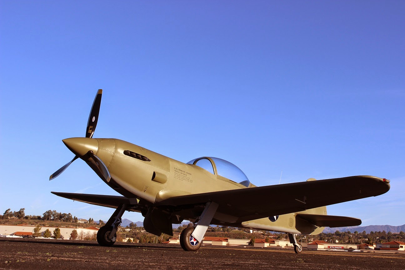
1. Bud's Latest Report
2. Ray's Latest Report
3. Rib Smasher Update
4. Retaining Wall Status
5. New (Future) Project
Let's get started:
1. Bud's Latest Report - I've had a few email or phone conversations with Bud recently. He has been hammering away at his "gripe list" and recently said in a quick email:
After 2 1/2 months of work, the Florida Jaguar is back in the air. Did a round robin to Lakeland today; the tail-wheel functioned as it was supposed to and the engine ran like a champ.
Then a few weeks later Bud wrote:
During the engine rebuild, I had to replace both sets of tapered bearings in the
PSRU (one set fell apart in my hands). Now, at Steve Rogers suggestion, I shut
down in coarse pitch. Before start, I crack the throttle and set the prop lever
to full forward. Just before T/O, I cycle the prop. This procedure seems to be
working well.
There were no detectable prop vibrations until I started
working on cruise and endurance settings. Once I went below 2400 rpm the
vibration started and became worse with lower rpm. My initial reaction was prop
balance, so I did a dynamic balance. The max allowable reading is .14; mine was
.36. After balancing, the reading was .06.
The next flight showed that the balancing job had no affect on the vibrations I was experiencing. Play in the blade rotation was normal but pulling a blade fore and aft produced quite a bit of movement. I suspected the spacers in the prop hub but someone else noticed that the entire hub was moving. I thought that I was going to have to replace the PSRU bearings again.
George said to pull the prop and tighten the large nut to put more pressure on the bearings. Also, I removed the weights installed from the dynamic balance. This decreased the vibrations, but not enough. I added a second spacer on top of the bearing and now there is no hint of vibration until I go below 2150 rpm. Since this well within operation range, I'll stop there.
The airplane begs for a military paint scheme but mine will have to stay in the primer while I save my pennies.
Bud also sent some of his first photo shots aloft:


2. Ray's Latest Report - Ray has been methodically solving his engine issues. The biggest issue has been the fuel control. His engine uses a diaphragm operated mixture control unit (essentially a mechanical fuel/air mixture computer). With the help of a local tech, the unit was evaluated, then removed and sent to the factory for modifications/repairs. It has now been put back onto the airplane and dialed in. Here is the latest report from Ray:
I finished up cleaning up the oil mess (from previous breather leak) today and got the engine running. It runs like it should now. Tomorrow I may have it out again for Warren to give it his blessings as completed. If you will be able to get by in the next week or so I will still have it operational. After that it will be blocked in by the wings while I slosh them with sealer. Still on the list is the door for the block heater. I think that I’m running out of things to be done here so it’s time for the painting to start. I think that right now flying should begin by late spring after I get some recent stick time.
Today the only thing was a small leak on the oil fitting from the oil cooler to the block. The new oil line going into the prop gear box appears to drop the oil pressure by about 5psi at idle and no difference at speeds above 800 rpm, this with 140F oil temp. The big thing was the fuel control. If the fuel /air ratio checks out OK it’s finished. The throttle response is sharp open and closed, no hesitation and the engine runs smoother from the better combustion. Starting will take a few tries to figure out what it likes. So far engine temps aren’t a problem, I can’t get it to really get very warm. Water temp never got above 150F, oil never got above 140F. This was with the cooling doors fully closed and OAT 55F. I think that it should run warmer with the cowling on.
Tomorrow it’s over to Jerry's welding to put on the mounting plate for the blowoff valve that I got from Vortech. It should take care of pressure differential on the throttle plate.
There it is, straight from the source. Looks like late spring for Ray's 1st flight. Here is another pic from my last visit to see Ray:

Nice work, Ray. We are all elated to see you getting so close to your first flight.


Then, I took the pressure up to 6,000 psi:

This is a lot of pressure! To give you an idea how much pressure this is, here is an example. My smartphone is about 3"x4" creating a footprint that is approximately 12 sq. in. If there was 6,000psi holding this phone down to the table, that would represent a force of 72,000 lbs. Imagine trying to pick up a 36 Ton cellphone!!!!
I will try to press some test pieces up to 6Kpsi and see if I need to go higher. If I do find that I need the pressure to go higher - I will do it from a "more remote" location.
While testing, I want to try to make a part (or parts) that I can use down the road. The first part that I selected is a bulkhead part that is under the cockpit floor just behind the main spar, shown here:


I have to have rubber to put on top of the blank to form the parts using this process. Over the summer, I frequently stopped by my local tire store and checked the dumpster for tire inner tubes. I found 4 large tractor tires that I collected in a pile on the shop floor:


4. Retaining Wall Status - Before the weather turned completely sour and made it impossible to pour concrete, I was able to pour the last cap pieces on the 1st phase of the retaining wall behind the shop. Here is a picture of the major portion of the wall:


That's it for this project until sometime next spring. Once the temps start to go up and the ground dries out I'll get out there and try to finish up this project. Until then, I'll be in the shop trying to make Prowler parts.
5. New (Future) Project - Here is a project that I've been thinking about for a long time. The shop is out in the country and we have electric power supplied by Pacific Gas & Electric. Like most things in California, this state has turned PG&E into a means to fund more welfare programs. So, the cost of electricity is skyrocketing thanks to "Cap & Trade." In an effort to lower the power bill around here, I would like to run the high draw machines (mostly the mills and the MotionMonster) using a diesel generator. This will keep the monthly power bill out of the "Upper Tiers" of use that end up making electricity cost nearly $1/KWh.
In addition, since we do have occasional multi-day power outages (caused by a variety of factors), this unit will also serve as a back-up generator to power the entire property (house, shop, well, etc.).
I recently purchased this unit from a friend for a reasonable cost. The generator end and the control panel are in good shape, but the diesel engine needs to be replaced. More on this over the next year as I search for a replacement engine and get this beast running. Here's a pic: