Hello Everyone,
Merry Christmas to all - Florida style:
This display was located just inside security checkpoint at the JAX airport this year.
Yup! I'm still around, and I'm still doing Prowler Aviation work. However, now I am back to the normal "day job" and it has been a fairly busy year at work. I really want to start to get back to doing more of these Prowler blog updates, but it seems like I always have something higher on the priority list, so it ends up getting pushed to the right. I will endeavor to do better. Let's say that I will make that my New Year's resolution for 2023!
The last blog update was dedicated solely to the work I have finished on restoring an old Hardinge HCNC lathe that was in need of some updates. I don't have a lot more to update on machines and such. However, I do have a bit of Prowler related material that I have been holding onto while waiting for an opportunity to get going with a blog update for it. Most of the Prowler related update info that I have is on one of the following topics: 1) work done to the "Sea Prowler"; 2) Updates on Francis' progress on the French Prowler; and 3) Parts that I have made to support the work that Vaughn is doing, or updates on his project's progress.
For this blog update, I think I will address the "Sea Prowler" items and the work that we have been doing for Vaughn's Prowler project. Then, I'll put all of the pics and updates that I have gotten from Francis into a single blog post of it's own - which I will do right after this update. I will shoot to get this current blog post done by Christmas and then get the next one posted by New Year's.
So, let's go........
Vaughn's Prowler Project (Kit #13) - I introduced Vaughn and his project in a previous update (
here). This kit was originally bought and partially built by Mr. Ron Chamblin of Jacksonville, FL. Ron sold all of his Prowler projects to Rick Pelliciotti in 2008/2009. Some years later, Rick sold this kit to Roy in Indiana. Roy had it for sale for a while until Vaughn purchased it in late 2020. Here is a pic from about the time that Roy bought the partially completed kit:
Once Vaughn got the airplane in his hangar and got familiar with the airplane, he started to make a list of things that needed to be fixed, modified or just needed finishing. Here are a few of the first items on the list.
MLG Alignment Mods to Torque Box - One of the first things on that list was the alignment of the MLG. Vaughn
noticed that the wheel on one side was not tracking correctly and when
retracted into the wheel well, the strut was not parallel to the spar in
the gear well. After some discussions, we determined that the torque box was possibly mis-aligned during wing construction and the easiest "fix" would be to move the pivot link inside the torque box. After taking some measurements, Vaughn determined that the strut was approx. 1/4" too far forward in the gear well. With that info, all we had to do was the math:

What the math told us, is that the pivot link support inside the torque box was going to have to move about about 0.054" (rounded off to a 0.050" piece of steel plate). That would be possible to do by placing a shim on one side of the pivot link support. But, first, the torque tube would have to come out - that is a more difficult task. The first step to remove the torque tube was to make room for it to come forward into the wing, past the transverse bulkheads between the nose ribs in the center wing. Here was the ruff removal to accomplish that:
With more room to pull the torque tube forward, the next step was to cut into the top of the wing and the top of the torque box and remove the bolts holding the pivot link to the aft end of the torque tube. Then, after removing a bunch of bolts on the wing joint plates, the torque tube could be removed from the torque box (the spherical bearing has to come along with it). Here is the tube removed:
With the torque tube removed, he could remove the bolts that held the pivot link bracket and remove it. Here is the bracket with the new shim installed in place:
Another view:
Here is the pivot link that was removed, inspected and replaced into the torque box. If I remember correctly, Vaughn had to modify some of the bolts in the pivot to take out some backlash that was in the clearance holes in the pivot link and the threaded holes in the torque tube. Here is what that looked like:
After getting it all back together, Vaughn was much happier with the operation of the MLG.
MLG Uplocks - With the MLG struts properly aligned and tracking into the gear wells properly, the next item on Vaughn's hit list was to install MLG uplocks. He copied Ray's work here and installed a stud to the MLG yoke that engages with an automobile OEM door lock unit. This design works great, it's reliable and can hold up multiple times the weight of the MLG during during G loads on the airplane. Here is Vaughn's installation:
Nice work!
Radiator Mods - While working on the MLG (and while I was fabricating radiator parts), Vaughn was simultaneously planning his FWF installation and what he would need for systems to support that. He is planning on using a PowerSport rotary engine package for his Prowler. He determined what he would need for heat rejection with this PowerSport FWF package and had the proper sized radiators made for this. Once I got the radiator parts shipped out to him, he was able to start putting it all together.
Here is a pic of some of his fabrication work on the radiator boxes:
Since his FWF setup will not need as much heat rejection as a large V8 engine, and because he had very efficient, multiple flow radiators made, his radiators had a much smaller cross section than was needed for the old George Morse design. So, notice the baffles that Vaughn made to surround the radiators and, yet fit into the original channels:
Nice radiators! Here is what the (somewhat) final installation will look like:
Same view here, except notice the part of the follow-up door installed on the MLG strut!
Parts #1 - I have been fabricating parts for Vaughn in several rounds. This first batch of parts that I shipped to Vaughn included MLG wheel well framing parts:
Cockpit framing parts, including the back seat setback and seat pan, instrument panel frames and brackets:
Radiator mounting flanges, door linkage brackets and radiator doors:
More MLG parts including hydraulic actuators, actuator mounting brackets and some more framing pieces:
I got most of the above parts shipped out to Vaughn in May 2021. Then, I started working on the next batch:
Parts #2 - Because of the size/length of the radiator attach angles and the instrument panel flange, I did not send those with the first shipment. After I fabricated the radiator lower skins for Vaughn, I included those with the previous parts and got them shipped out to him in June 2021. Here they are:
Here is a quick pic of part of the lower radiator skin fabrication. This gets the proper radius bend on the forward leading edge of the radiator lower skin.
It is kinda low tech - but, it works good!
Parts #3 - The third batch of parts that I made for Vaughn was a set of radiator door side formers. To make these, I needed to cut the blanks that were to be formed. Then, they are clamped between the two form blocks. You bend the flanges one way for one side of the door, and bend the flanges the other way for the other side of the door. Here is the pattern, a forming blank and the forming blocks:
Here is the paper pattern, a metal pattern, and 4 forming blanks:
Drilling the tooling holes:
First blank in the form blocks and bending (forming) the flanges:
One completed radiator door former:
Here are two complete sets of radiator door formers:
Ready to ship:
With radiator parts now finished....time to move on to the flap actuator.
Parts #4 - I don't think that Kit #13 was built with the flap actuator installed onto the forward side of the aft bulkhead beneath the cockpit floor. At least, it was not there when Vaughn bought the kit. So, the first step for me was to fabricate all of the parts to make an actuator:
Then, I jigged them all up in the fixture that I made several years ago:
I tack welded each of these parts well enough to hold them in place and got this:
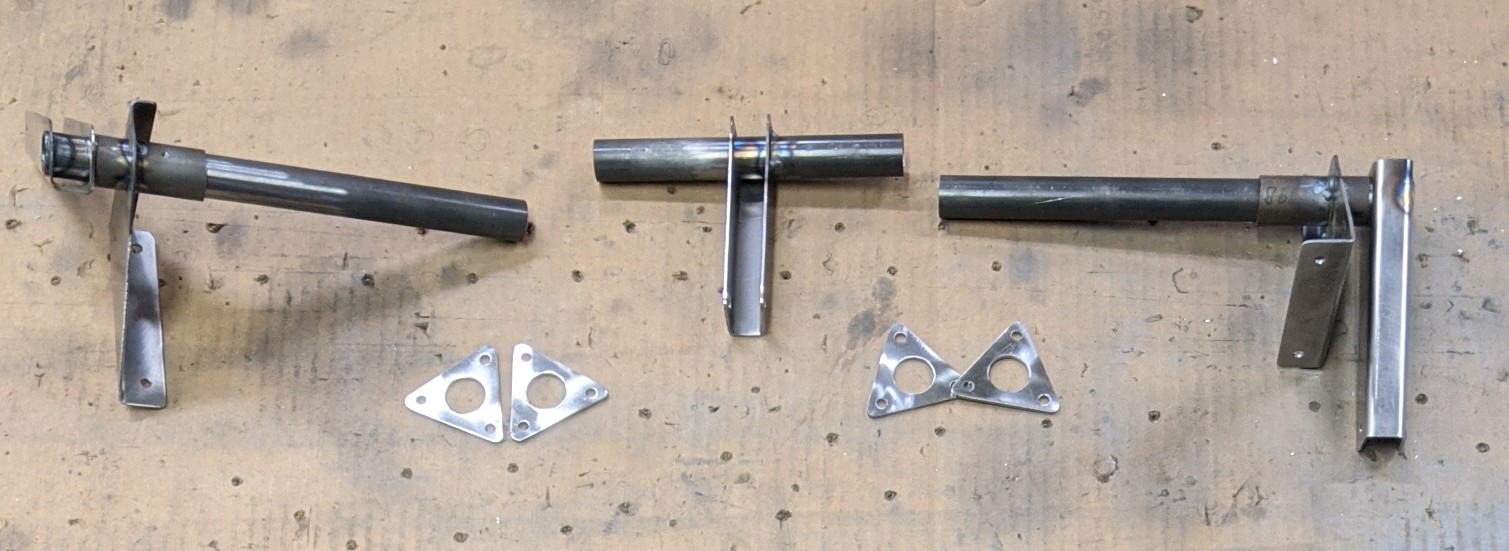
Because Vaughn's kit is mostly assembled, he doesn't have much room to install this actuator. So, to make it easier (to make it even possible) I was going to have to use another of Ray's proven modifications and divide the actuator up into 3 pieces. Here is the fabrication of 2 sets of triangular parts that will make it possible to install this actuator in 3 pieces and then bolt them all together:
Three pieces plus the flanges:
Back into the jig/fixture for more tack welding:
Here is the final product that is tack welded together.
Since I lost my TIG welder (he up and moved his family clear across the country!), it is hard for me to get airplane parts welded. I was able to tack these parts together for Vaughn and he has a welder that will do the final welding on this actuator. Here are the parts ready to put in the box:
I also included 3 sets of radiator door actuator brackets that Vaughn needed:
Vaughn plans to use these to devise his own door actuators from small linear electric actuators. I'll update you on his design here. If it works well, I may adopt it as the new system for this on the Prowler. More to follow.
Parts #5 - The most recent part I fabricated for Vaughn was the forward engine compartment bulkhead. I refer to this part as the "horse collar" - cuz that's what it looks like to me. Others have said it looks more like something you find attached to nearly every toilet in the world. You decide.
Anyway, Vaughn is starting to plan out his engine installation and he needs this part to be able to begin to mock up his FWF project. There is a bit of a story behind finding the former for this part, but let's just say thanks to Cabi for providing this form block for making the horse collar for the original (smaller) Prowler. This is the former that was used to make the "horse collar" for the very first (smaller) Prowler. Here is the form block for making this part:

[Sidebar - Vaughn chose to go with this smaller sized part because his FWF package weighs less
and has a smaller cross-section size up front. It is very likely that
he will have to move his whole FWF package forward some to keep the CG
in the range of all the current Prowlers. By going with this slightly
smaller front bulkhead former for the engine compartment, it should keep the side-view silhouette
of the airplane looking like it should for a Prowler (keep the same "lines"). We reasoned that the larger fwd bulkhead of the production Prowler moved forward might give his plane a more noticeably blunt front end, right behind the spinner. I think he/we made the right choice.]
Here's a side view of the former that shows the angle of the flange that varies as you go around the outside perimeter of this part:
I did not have a pattern for making this part. So, I made one from the form block backer. I traced the backer onto cardboard and then added a 1" flange on the outside and an 1/2" flange on the inside:
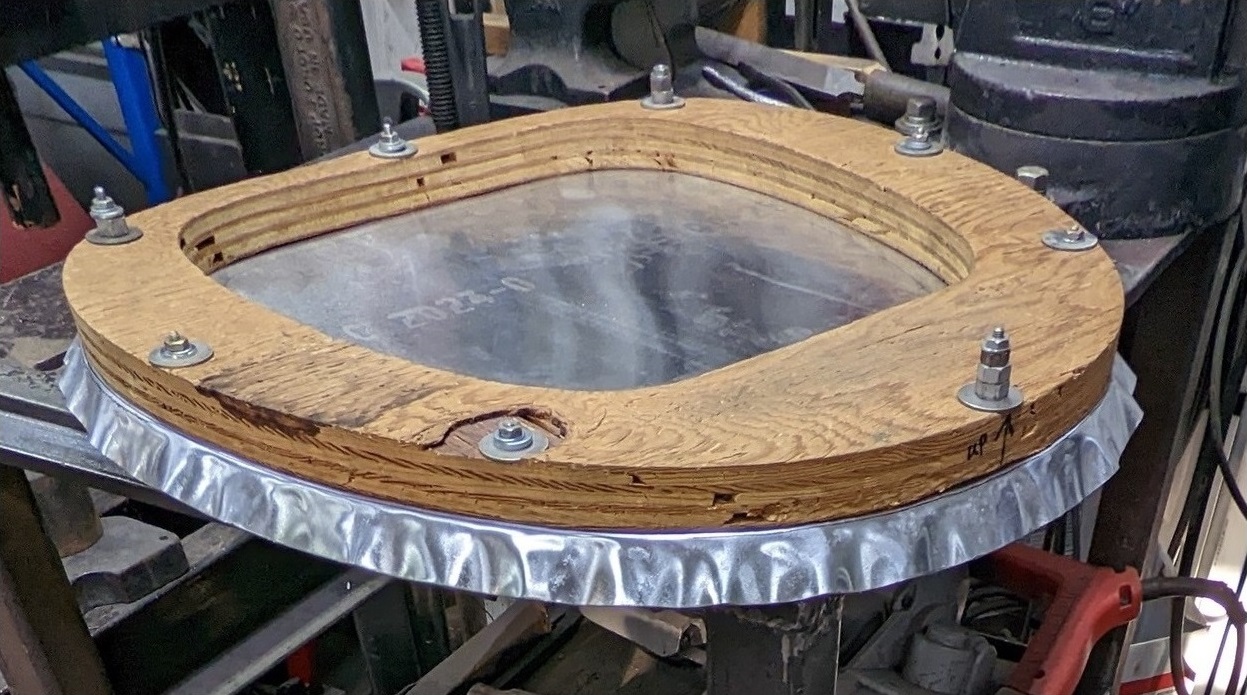
Then, I used that pattern to cut out a forming blank. Notice how "wrinkly" the 2024-O material looks. That's just from holding/moving the piece while using a shears on it. It flattens back out once it is in the form block and you start to hammer, stretch, shrink and move the metal during forming:
Then, sandwiched the blank between the form block and the backer:
Here's another side view:
Once the blank is in the form block, you simply start hammering the edges down. As you do that, the outer perimeter gets wavy:
The flange gets wavy because the outer perimeter of the flange must get smaller (shorter) as you form the flange. You are essentially making the outside edge of the flange form a smaller, concentric contour. The metal in the outer perimeter of the flange must "come together". The best way to do that is to take the blank back out of the former and use a shrinker to take the "wavies" out of the flange:
Then, you have to put the part back into the former and hammer the edges down more until they fit tightly to the form block. As you do that, the material will get wavy again. In this picture below, I put X's on the flange where I do not need to shrink it any more:
Each time you hammer the flange it will get wavy again, so you take it out and shrink the outer edges more. It is an iterative
process that you go through until you get the flange to form snugly to the form block without any waves, gaps or buckles. Eventually, you get the flange to fit nicely.
Once the outer flange was done, I cut the center out of the part and hammered the inside flange. Unfortunately, I forgot to grab a pic of that. The inside flange is easier because you do not have to shrink the edges-the metal on the outer perimeter of the inside flange actually has to stretch to make the inside curves. The danger there is that you have to be careful not to hammer the inside flange too much, too fast - especially in the corners. Otherwise, the material will try to stretch too fast and it will fracture. Lots of little hammering operations is best. And, you try to hammer the metal from the straight flanges toward the curved areas.
With the inside flange formed, all that is left to do is check the part for warping. If the part does not sit flat on a table, you have to carefully shrink the outer flange in the right places to take the warp out. Usually, a little bit in just the right places is all you need. Then, you trim the flanges to make them uniform. With that, you get the finished product:
I also use a combination of files, sandpaper and Scotchbrite rol-lock disks to clean up where the shrinker mars the metal. You can get some of the lines out, but I don't try to get it all. You'll thin the metal too much. Then, give it a clean up with a Scotchbrite pad on the faces. Here is the back side:
You can still see the lines from the shrinking. But, this is not a part that is visible on the plane without removing the skin panels. So, I don't try to get all the lines out. If you need to get it looking perfect, you'd probably want to use some filler material and then sand it real nice for painting. It is up to the builder to make it as clean looking as is desired. Here's a quarter view:
After some final clean up, I fabricated a hard sided shipping container for this part. The part is formed from soft 2024-O material and must be heat treated before installing in the plane. Vaughn is going to take care of that. So, I wanted a shipping box for it that would protect it better so that it wouldn't get bent, or damaged:
Off it went to Vaughn:
The next items on Vaughn's wish list are radiator side fairings and a set of engine compartment longerons. More on this in a future update.
The "Sea Plane" Work - For those that are new to the blog, this is the airplane that formerly belonged to Ernest ("EZ") up in Seattle. Several of us have begun to refer to it as the "Sea Plane" or the "Sea Prowler" because of it's ultimate salt water demise. After EZ's forced landing, this plane sat off the beach of McNeil Island in Seattle for 4 days and was submerged by the tide, twice a day. This is possibly bad humor, and no one is intentionally being disrespectful (or making light) of what happened to EZ - but it is a fairly accurate way to describe this plane. Here is an older pic I have of it in my yard (you can see the outboard wings laying along side the plane):
In a previous post I described making and installing hitch receivers that will eventually support the airplane in it's next roll as either a Prowler Aviation billboard, or possibly as a "Prowler on a post" that will greet folks that arrive at an airport somewhere (yet to be determined). Here's a pic of the mounting points I installed:
Next, I have two tasks to complete for the Sea Prowler - I need to fabricate one more mounting point on the keel of the plane aft of the cockpit to complete the 3 point mount that I am envisioning. The other is to re-skin and re-mount the inboard flap segments that got badly damaged when the airplane was being salvaged out of the Seattle harbor. The salvage company just put slings under the airplane and lifted it out of the water with an excavator onto a barge. The slings damaged the wing fairings and inboard flap segments extensively.
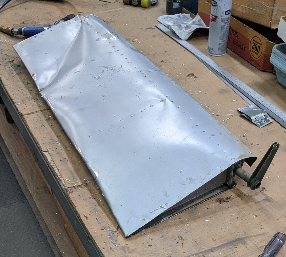
I have removed the inboard flap segments. One side came off pretty easily by pulling the hinge pin of the hinge that holds it in place. The other side, I could not get the hinge pin to pull out - no matter what I tried. So, I ended up having to drill the rivets out of the entire hinge on one side. Here is the LH flap after I got it off the airplane and on the bench in the shop. You can see the damage:
Here is a picture of both inboard flap segment frames with the skins removed:
The inboard flap frames are salvageable and I am going to keep them and re-skin them. I'll have more pics in a future update when I am finished with the re-skin of them.
While working on the Sea Prowler flaps, I decided that it will not be able to live the rest of it's life in my front yard next to the pumphouse. At some point, it will have to be moved to a new home - wherever that may be. I have a trailer [that I bought from EZ, (who got it from George) that is now with Ray carrying his Prowler] that I can use to move a Prowler airplane. But, since the Sea Prowler does not have any landing gear, I was going to have to find another way. I decided to......wait for it......BUILD ANOTHER TRAILER!! Ha! Bet you didn't see that coming!?!?
OK, maybe you did - given my historical penchant for trailer building. Anyway, I had some old axle spindles laying around that I cut from an damaged trailing link axle that my neighbor had given to me. Here is a pic of one of the spindles still as it was cut from the trailer (on the left) and one that I had cut up to get ready to modify to install into a new axle tube:
By trimming the trailing link down to a six sided piece, it would be easier to put in the lathe and machine down to a clean plug that could be fitted into the new axle tube. Next step was to find some steel to make the axle tube from. I found some surplus drops at the local steel place that I was able to weld together to make a new axle tube. Here is a pic of both spindles mounted in the new axle tube:
Here's a closer shot of the way that I mounted the spindles in the new axle tube. I machined the cylindrical ends of the spindles so that they would just slip into the ends of the tube. I drilled several holes in the end of the tube so that they would line up with the steel on the inboard ends of the spindles. This would allow for a fillet weld around the end of the tube to the square plate, and also several plug welds (aka rosette welds) around the inner ends of the spindles. Here's what each end looked like before welding:
With everything lined up and straight, I welded everything up. I did the plug welds first thinking that the heat from these was less likely to warp the spindles out of alignment with the
tube. Once the rosette welds were done, I welded the end of the tube to the square flange on the spindles.
Since each
axle spindle is only rated for 1250 lbs, I am stripping the Sea Plane of everything heavy and building the trailer to haul a max load of 2,500 lbs. With the trailer limited to a max load of 2,500 lbs, I can use lighter materials to build it. I had a bunch of tubing that I had salvaged from some old tractor shipping skids several years ago. I used that to make the basic frame and deck of the trailer.
So far, the only things I have needed to buy for this trailer were the springs, wheel fenders, a hitch coupler and a jack stand. I was able to order a set of 1,500lbs springs fairly inexpensively and added those to the build (above).
Since there will be several special requirements to haul the Sea Prowler, I designed this trailer specifically for that purpose. However, after this trailer has served that purpose, I have made some provisions to do some fairly easy modifications to make it into a general purpose utility trailer. The biggest special requirement is the distance between where the weight of the plane will bear onto the trailer (affecting the weight and balance of the trailer) and the spinner on the front. I had to build a long tongue on the trailer to allow room so that the spinner will clear the back of a truck that is pulling it. Here is the trailer just after fabricating and adding the tongue:
With the underside welded and finished with paint, I flipped it over and put on some wheels to see what it was going to look like:
Here is the Sea Prowler trailer project as it currently exists. Those fenders are just sitting on the wheels right now as I try to figure out the best way to permanently attach them to the trailer:
I am also reconsidering the wheels. Those are 15" wheels with trailer tires on them in the pic above. They really don't need to be that big. I have a set of smaller 14" wheels that I might find some trailer tires for and use those. And, that will change where I mount the fenders. So, this is a kind "engineer it as you go" type of project. But, that's what you have to do when you're trying to not spend a bunch of money and use what you have on hand.
So, that's it for this update. I hope you all have a Merry Christmas this year. Thanks for following along with me as I work to get this airplane closer to a limited production status. I am going to get started right away on the next blog update that will feature all the work that Francis has been getting done on the French Prowler. See ya next year.