Saturday, April 27, 2019

Another Prowler Shop Project - Rebuilding A Hardinge CHNC Lathe

As I mentioned in the last update, I've been working on another machine project on and off at the shop over the past year.  I wanted to break this update out of the normal Prowler blog updates, since this update deals with my repair and alteration of a "new" machine that I hope to use in production Prowler parts - and does not contain much info related directly to the Prowler aircraft.  So, if you're interest - Please have a look.  If rebuilding old CNC machines is not your thing, feel free to pass on this one.

Last May, I had a buddy who wanted to sell his CNC lathe to raise some cash to buy another machine he liked better.  He was tired of dealing with his Hardinge CHNC lathe with a Fagor 8025T control installed on it.  It was his only production lathe that didn't have an OmniTurn control and and he wanted to purchase another Hardinge lathe he found that came with an OmniTurn control - so, that way, all of his machines would then be the same.  I have actually worked on this machine for him many times over the years, so I knew pretty well what I was getting into.  The lathe wasn't holding position well on the Z axis and there was a few other problems that would need to be addressed.  The price was right, so I bought it from him.  Here's a few pics from moving day:
 I used the overhead gantry that I'd built for working on the 400 ton press to pick the machine up.  Then, I backed the trailer under it:
Here is the machine after I got it home to the shop and started to tear it down:
To start with, I did some research about this lathe.  What I've found out is that this is the very 1st line of CNC lathes that Hardinge ever made.  These machines were built in the late 1970's and this machine was #109 in that series of lathes.  Unlike our current technology, anything built in the 1970's that had a computer attached to it was BIG!  This lathe was no different.  Here is pic from the cover of the maintenance manual that I found online:
Check out that control!!  It's 1/2 the size of the lathe!! And, your smartphone today probably has 10,000 times the computing power than that old control did in 1979!  If you follow that square tube that comes out of the top of the control and goes up and over the lathe you'll see it is attached to large electrical cabinet behind the lathe.  That cabinet is about 5 feet tall, 3 feet wide and about 1 ft deep.  It was designed to hold some huge, high current switches, breakers, relays and spindle control amplifiers that were the cutting edge technology of 1970's.

Now, sometime in the late 90's or early 2000's someone did a retro-fit to this machine and installed the Fagor 8025T control that is on the machine now.  That got rid of that massive control in the foreground of the above picture (I wonder whatever happened to that??).  However, when whoever did this retro-fit installed this new Fagor 8025T control, they left a lot of "stuff" in the machine that was no longer needed.  There was a ton of "dead weight" that was hanging out in this machine that could be gutted out and gotten rid of.  More on this later, but I figured, at the very least, the large electrical cabinet in back could be deleted and the machine streamlined significantly.

After some initial tear down and investigation, here is the punch list I've come up with for this lathe project:
1.  Find out why the Z axis was not working well (loosing position and not repeating well - like during threading operations);
2.  Remove the huge electronics cabinet off the back side and put the needed components into a smaller enclosure;
3.  Overhaul the X axis servo, and belt drive system - it was kind of a hodge-podge mess;
4.  Re-wire the machine with a single point power hook up and convenient switching to power up the control and the spindle systems;
5.  Investigate the tool turret system and try to get it to be usable again;
6.  Rehab the coolant system;
7.  Rehab the collet closer system and try to get it working again;
8.  Re-install new plexiglass into the enclosure doors.

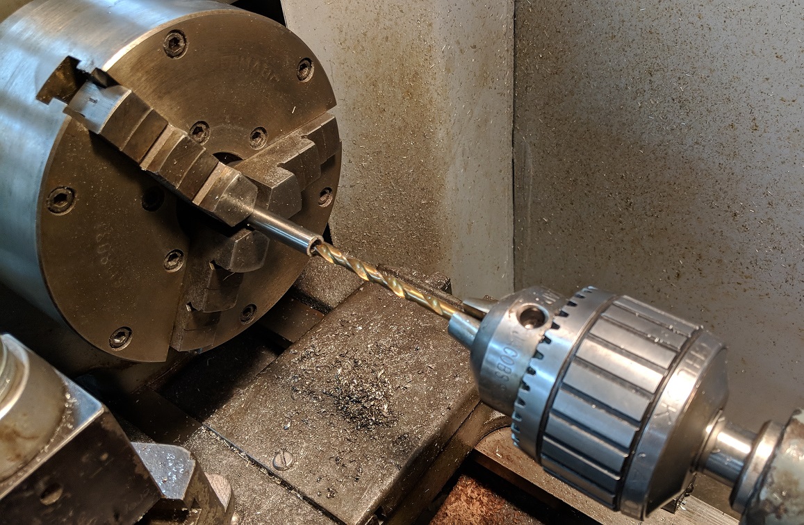
1.  Z-Axis Issues - So, one of the big problems with the machine was that the Z axis was not working well.  It was loosing position often and the control was giving Z axis following errors.  It was also not repeating its position well - like during threading operations.  After the initial tear down, I started focusing in on the Z axis system.  What I discovered is that the Z axis ballscrew was designed to be held in position along it's long axis by a bearing block system.  There are basically two thrust bearings that are tightened towards each other by cylindrical bearing retainers with OD threads that are threaded into a big block of steel (from the each direction); and that block is rigidly bolted to the ways (main body of the lathe).  Here is a pic of the Z ballscrew (under the covers) and the bearing block on the left end (the servo turns the ballscrew via a cogged pulley on the right end):
Here is the pulley end of the Z axis ballscrew:
Turns out, those bearing retainer nuts had merely gotten loose and each time the Z axis changed directions, the Z ballscrew would turn about 1/4 of a full turn and the cross-slide would not move (while the bearings "slopped" inside the bearing block).  So, just simply tightening up those retaining nuts took the backlash out of the Z axis ballscrew.  After a few other small tweaks and putting it all back together, the Z axis is nice and tight and working well again.

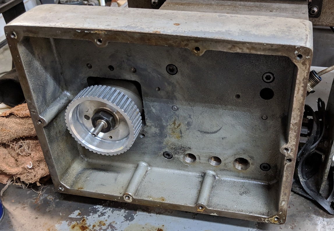
2.  Huge Electronics Cabinet & Re-wiring - As I previously mentioned, when the F8025T control retro-fit was accomplished on this machine, there was a lot of junk left on the machine that could have (should have) been removed.  This was very true with the electrical cabinet.  Before I moved this machine from my buddy's shop to mine, I decided that it would be easier if I removed that main electrical cabinet (also since I wasn't going to need it any longer, why leave it on).  Here is a pic of the inside of that 5' x 3' x 1' electrical control panel just after I disconnected it and removed it from the main body of the lathe:
Looking closely at this cabinet under the cover, you can see that the only component that is in use on the left side of this huge cabinet is the black box near the top.  That is the spindle drive controller/amplifier.  All the rest of the "stuff" on the left side of that box is not used and can get chucked!  On the right side, the huge 60 amp switch on the upper right can be replaced with a 30 amp machine switch that is about 1/10th the size.  The group of semi-conductor relays on the lower right can still be used, but about 1/2 of them are no longer needed.  They have been replaced by relays in the F8025T control and can be deleted.  The remaining "stuff" in the middle of the right side of the cabinet can be used as is, or replaced with a smaller updated component.  Overall, I surmised that the items that are actually being used in this LARGE cabinet could be removed and installed into a much smaller cabinet. (I have an idea for another application for the large cabinet, but that'll be another project for a future update.)

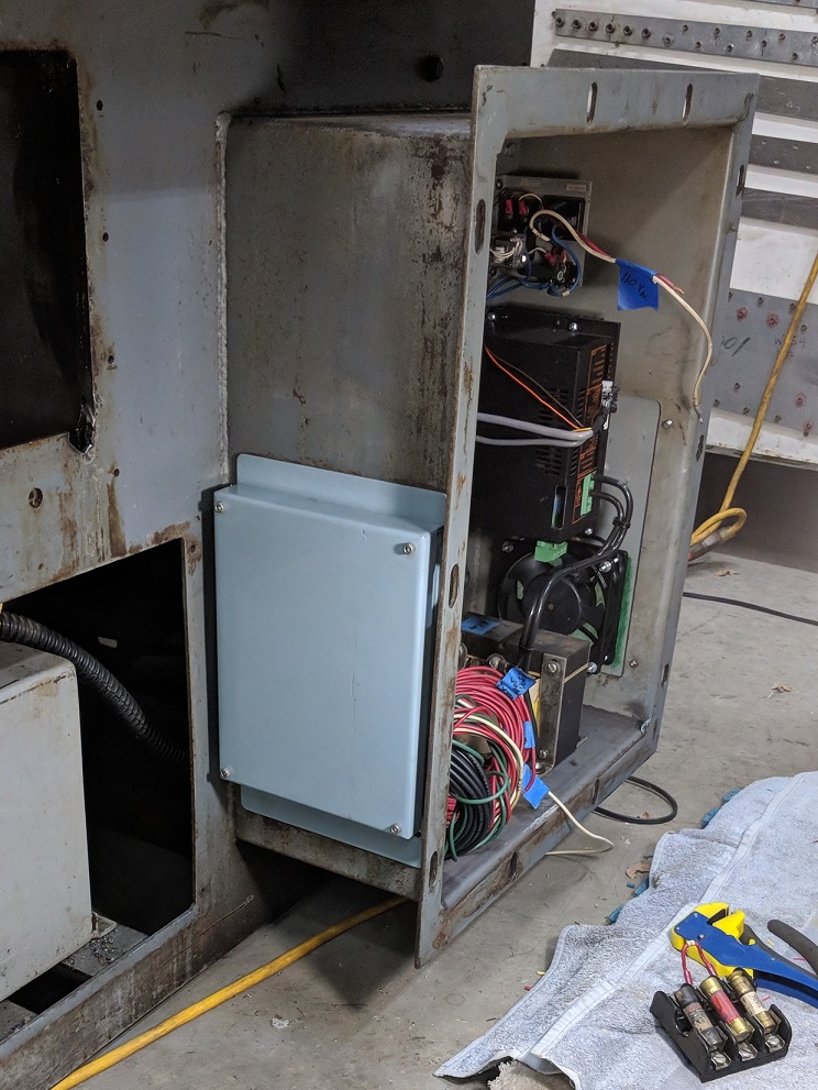
Here is a picture of where and how this cabinet was attached to the machine.  It was simply bolted to a sort-of "tunnel" that was welded to the back side of the lathe.
The various control and power wires were passed through this tunnel and then into the big cabinet.  After looking this over for a long time and taking some measurements, I decided that all the electronic components that were needed to run this machine could be mounted into this tunnel.  One big problem was going to be that divider plate welded down the middle of the tunnel.  Also, you can't put a bunch of electronics into a small space and not ventilate it.  Things will overheat.  So, I was going to have to include some kind of ventilation fans and filters.  Oh, and I'd have to fabricate a cover for it.

First things first - that divider had to go.  A few minutes with the 4" angle grinder (with a thin cutting blade) and a lot of sparks later..... The divider was gone:
With that gone, I could start moving the components over from the big cabinet to the small one.  First, I traced out the circuit diagrams and took lots of pictures of the existing hook-ups, then that old divider plate became the new plate to mount the components on in the top portion of the tunnel.  With that component plate in place, I started moving components over one-by-one.  Here is the current result:
At this point, everything in the new cabinet is moved over and hooked up except for the 115Vac items.  The wires that are still hanging out of the tunnel all have to be somehow or other get hooked up to 115Vac power - which is still pending (I haven't done the main power hook-up wiring yet).

Next up, I started chasing down how to ventilate this tunnel.  There were some large rectangular access plates that I had removed from the lower sides of the tunnel.  Also, the big, old electrical cabinet had a large air filter set-up.  I decided to use that and, somehow, attach it to one of those lower access plates.  Here is what I came up with after I cut out a few chunks so that it would all fit together:
The lower access plate (on the left, above) got a square hole cut in it.  The old filter assembly got a slice cut out of it.  Here (below) is the new system after welding the cut pieces back together:
There are stand offs at each corner that the cover bolts too.  This provides and air gap all around the edges of the cover.  Here is a test fitting of the new filter assembly on the tunnel:
Next, add paint and some furnace filter material:
AND..... air filter assembly is completed:
Now, I had to figure out a way to get air to move through the cabinet.  A 115Vac cooling fan would work best.  I found one locally sourced for $15, got it to the shop, took some measurements and cut a hole in the other lower access plate using a fly cutter in the mill:
Here's the access plate with the holes cut and the fan that will mount to it:
I decided that there was enough room on the access plate to also fit an electrical hook-up box to it that will be used for hooking power up to the machine:
And:
Add paint and a little more furnace filter material:
Here is the fan and power hook-up box mounted to the other side of the tunnel:
That all came out pretty nice.  I'm happy with the results.  Moving on to the X axis work:

3.  Overhaul Of The X-Axis Servo And Drive System - Here is a picture of the X axis drive set up before I stripped it all down.  You can see that it is a very "hodge-podge" set up with lots of plates, extensions, shims, etc.:

From these pictures, it may not be immediately evident, but it was not an optimal and there is much room for improvement here.  The servo that was installed on the X axis is quite oversized (servo power capability and physical size).  A properly sized servo will negate the need for that big aluminum block spacer between the servo and the mounting plate.  Also, the cogged pulley on the right in the top picture is very worn and needs replaced.  After removing the servo and the aluminum cover plate here is the cogged pulley that drives the X axis:
The pulley is pretty badly worn where the belt runs on the outer edge of it.  It looks corroded too, like whatever someone was using as a coolant wasted away the aluminum where the belt ran. Here is the hub that the pulley attaches to on the end of the X axis ballscrew:
I tried finding a 1" slab of that cogged pulley material that I could machine to make a new one identical to the existing, but I have been unable to locate any at a reasonable cost (most places wanted me to buy a 10' bar of the stuff!!).  I beat up eBay an Amazon and found one new cogged pulley that might work.  It is the one on the left here (old pulley on the right and ballscrew hub is below):
The new one I found has the correct specs with regard to the diameter and number of cogs, but it is much thinner than what is currently on the machine.  That may not be a big issue as long as the small pulley on the servo can be made to align properly.  Also, the center boss on the new pulley is too small to adapt it directly to the existing hub.  Here's what that looks like:
So, I'm going to have to find another way to adapt it.  (Or, I might put a big piece of round aluminum bar in the super spacer on the mill some day and experiment with making my own replacement cogged pulley from scratch).  More to be done here.

As for the servo itself, it is not the correct shaft size, not the correct physical size and the max speed is rated too low for the machine (F8025T control).  The original servo went out on my buddy, so he bought a replacement off eBay.  But, unfortunately, he got one that didn't have a high enough max speed.  I installed it for him anyway, temporarily so that he could keep making parts - but, I had to limit the max speed on the control.  Now, I'm keeping an eye on Ebay for a cost effective option to replace this servo with one that is more properly sized and will allow the control to run the machine at normal max speed.  More to follow.

4.  Power Hook-ups & Machine Switching - Previously, the machine was powered from 2 different sources.  One source of 115Vac was fed into the large old electrical cabinet that powered the spindle and various relay controlled components (like coolant and collet closer, etc.).  Then, the Fagor 8025T control (which includes the power to the servos and servo amplifiers) was fed from another 115Vac source (literally fed from a cord plugged into a wall outlet).  Also, this machine originally used a cutting oil only coolant system with a huge tank under the lathe bed and was powered with a large 230Vac/3 phase pump.  Somewhere along the way, the 230/240Vac system was removed, the tank emptied and the coolant system was converted to a Little Giant 115V coolant system.

I'm going to continue to use all 115Vac systems, but I'll create a single point power hook-up for the 115Vac power.  Then, I'll install a remote switch on the front of the machine near the F8025T control that will turn on the spindle and power the coolant and various auxiliary systems.  I'll hard-wire the F8025T control to the same 115Vac system and continue to used the power switch that is already installed on the control to turn it on and off.  This way, I can turn on just the control if I want to jog the machine around and move the servos, etc. and not have to turn the spindle on.  That could also be used to make "dry runs" to test part programs.  Then, when ready to make chips, just hit the other switch to power up the rest of the machine.

5.  Tool turret system - This will potentially be the most difficult part of this machine restoration.  The lathe was built with a 8 position tool turret.  The tool turret was computer controlled and moved automatically when tool changes were called for.  This was accomplished using a complex system of pneumatic pistons, air motors, hydraulic actuators and an encoder type electrical position feedback system.  However, when the machine was modified and the F8025T control installed, the tool turret was simply bolted down and a gang-bar tool system was mounted to the top of the turret.  Here is the tool turret with the gang-bar removed:
Removing the top plate of the turret (the plate that the tools are actually mounted to) reveals a sturdy ring below that is rigidly mounted to the X axis and has two alignment dogs (black raised areas on the left and right sides of the picture below) and you see the top of the turret piston (area inside the bronze ring):
The way that the tool changer selected a new tool was to apply compressed air under the tool turret piston and lift the piston and the tool mounting plate upward.  Then, a rotary air screw turned the turret until the new tool was close to alignment with the tool position closest to the spindle "cutting position".  Then the compressed air was removed from the bottom of the piston and ported to the top side of the turret piston.  This forced the tool turret mount plate down onto the set of tapered dogs in the outer ring shown above.  Those male dogs you see in the picture above are matched with female slots in the bottom of the tool holder plate.  When the turret piston has compressed air on top of it, the air pressure holds the tool plate firmly down on those alignment dogs and keeps the tools perfectly aligned for cutting the part in the spindle.  Here is the alignment ring with the alignment dogs removed to expose just the top of the tool turret piston:
Here is the piston removed from the machine.  You can see the aluminum piston and the o-ring around the outer edge that seals the piston inside the turret pocket:
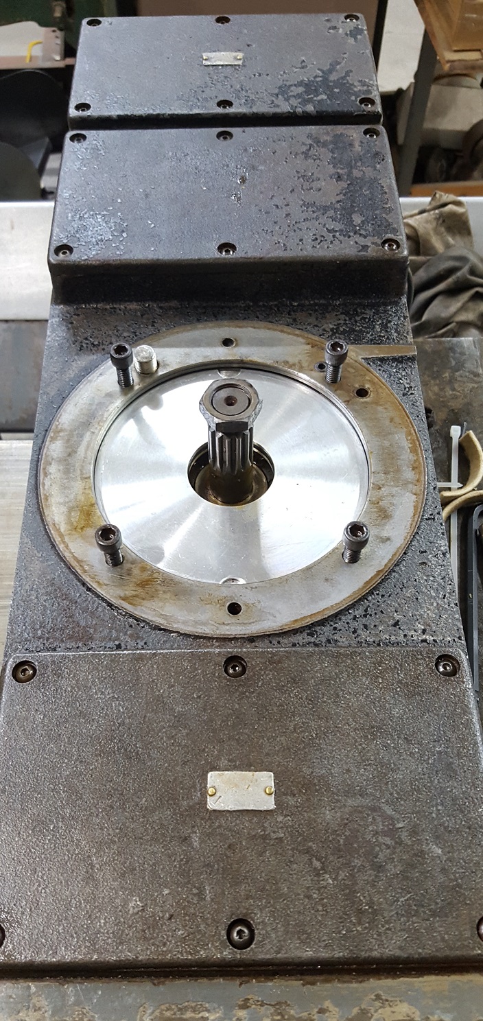
The thick piece of steel you see to the left of the piston (between the piston and the gear on the far left) was an alignment stop device.  When the turret was close to the desired position, a hydraulic arm would pop out from the side of the turret pocket and stop the turret in the desired position (the air servo would simply spin the turret until the old control made that hydraulic arm pop out and stop it in the desired position.  Here's a shot of that arm that stops the turret in the desired position:
The finer pitch gear that is attached to the tool turret piston (photo 2 above) engages the idler gear that you see in top of the hole in this picture:
That idler gear turns an electrical feedback encoder that is located under the rectangular cover just above the piston pocket in the picture above.  The control would know where the desired position was by using those gears and the electrical feedback encoder and and when the control saw the tool coming close to the "cutting" position, it would fire the hydraulic arm to stop the turret in that spot.  You can see the top of the feedback encoder in the foreground of this picture (my fingers are holding the feedback shaft):
Anyway, the point of all this is that (I THINK!) I might be able to use the turret again by installing a 2-way pneumatic valve system that normally ports air to the top side of the turret piston to hold it in the normal cutting position, then have a spring loaded "Tool Change" position which will put compressed air under the piston when a tool change is desired.  So, when you want to do a tool change the Gcode will have the control go into a pause routine for a tool change.  Then, the operator will flip the 2-way pneumatic valve to the (non-normal) "Tool Change" position which will put compressed air under the turret piston and allow the turret to be turned by hand.  With the new tool in the cutting position, the operator releases the 2-way valve and the compressed air will once again push the turret down onto the alignment dogs and hold the new tool in cutting position. At least, that is the theory.  The application might be a little more "fun."  More to follow......

 6.  Rehab the coolant system - As I mentioned above in the power system modifications, this lathe originally had a cutting oil "coolant" system.  Heavy, petroleum based cutting oil was used as a coolant and it was stored in a large tank under the lathe.  The cutting oil was pumped by a fairly large 230Vac/3-phase pump which was turned on/off by a large 3 phase switch in the electrical cabinet that was actuated by a 115Vac solenoid.  The 115Vac solenoid was controlled by the old controller using Crydom solid state relays.  Here is a pic of the accessible end of the coolant tank (and pump):
Using cutting oil like this is really not practical anymore and most coolants today are water based solutions that are much less toxic and much less expensive (imagine the cost of 30 gals of cutting oil today!!).  I don't have a definite plan yet, but I hope to install a medium sized coolant tank with a 115Vac pump that can easily be controlled by the F8025T control using the Crydom relays.  I have more research to do on as I design this new system and will follow-up on this when I get a firm plan together.

7.  Collet closer system - The lathe has a pneumatic collet closer system installed.  It has been semi-deleted and is not currently operating in automatic mode.  Here is a pic:
It does work manually by turning the  whole body of the closer, the threaded rod will close the collet holder.  I'm hoping to trace the electrical and pneumatic circuits in this system and figure out how the system is supposed to work.. Then, I will come up with a plan to repair, re-vamp, re-do, or otherwise re-install an operating collet closer system.  Even if it is just ends up being a manually controlled collet closer (.vs. controlled by the F8025T controller) - that would be an improvement over the current manually threading mode.


8.  Re-install New Plexiglass Into Enclosure Doors - I removed the enclosure bows so that I could work on the lathe more easily, but didn't have anywhere to store them out of the rain, so I turned them upside down on top of the machine, for now. Here is a pic as the machine currently exists.
Once I have all the mechanical type repairs done to the lathe, then I will endeavor to source some plexiglass and install new panels into the doors so that there will be good visibility inside the machine while it is running, but keep the coolant from splashing and flying about.

Well, that the current state of "dis"-repair of this machine.  I'll be pecking away at the hit list areas and will update on this machine again later.  Hopefully, you might have found some of this useful information for a similar project or prospective project.  Thanks for checking out the Hardinge CHNC Lathe project.  Now, back to the normal Prowler Blog updates.

Friday, April 12, 2019

Making Prowler Parts, Cutting Wing Rib Dies, Project X and Builder Updates

I can't believe that it's been over 5 months since my last update!  Life's been coming at me at warp speed lately.  I usually try to get an end of year blog update - but, that one slipped past.  Anyway, on to a new year!  I hope everyone had a great holiday season and that 2019 is off to a good start for you. 

I've had a couple months lately where I didn't have much support work to do for any of my current Prowler builders.  This has afforded me some time to tackle some of the projects that have been sitting around on my various work benches for far too long.  One good example is nose rib dies.  It's crazy to think that it's been over 4 years since I cut 4 nose rib dies so that I could replace 4 nose ribs for Francis!  Para 1. here:  (http://prowleraviation.blogspot.com/2014/12/more-rib-fabrication-and-santa-brought.html)

Since then, I've had 3 more nose rib dies cut out (rough cut with the band saw) sitting on a bench waiting for a chance to put them in the CNC mill and get them done.  Well, that time finally came this past couple months!  More later.

Also, I spent some "down time" in a hotel recently and used it to set up a Prowler Aviation YouTube channel.  You can find several videos of Prowler content here:
https://www.youtube.com/channel/UCvCZN-7jUt6ZKqn_KOFKV-Q
Head on over and check it out.  If you're interested, please subscribe.

In this update:
A.  Completing 2 Sets of MLG Torque Tubes
B.  Making Parts of a Tailwheel Hydraulic Actuator for Ray
C.  Hydraulic Repairs to 400 Ton Press
D.  "Project X" - Making Test Parts For New Owners of Another
      Kit Aircraft Company
E.   Finally Completed Dies For All the Outboard Nose Ribs
F.   Ray's Work on MLG Torque Tube Pivots
G.  An Update From Francis

Before I start with the Prowler update items, I've got a cool feedback type report to share.  For those of you that have followed my blog for a while, you may recall that I reported various times about working on and completing the installation of a backup diesel powered electric generator for my property.  (Item #4 here: http://prowleraviation.blogspot.com/2016/02/kit-15-has-new-owner-rays-tailwheel_17.html).
In mid Feb this spring, we had a freak snow storm in the Northern CA valley area and we got 6-11 inches of wet, heavy snow (depending on the exact location).  At the shop, we got about 6 inches.  To the north of us, they got more like 10-11 inches.  Check this out:


Now, I grew up in east central WI and snow like this isn't impressive to me.  But, for our area of Northern CA, this is not at all normal.  Typically, once each winter it snows just enough to make the ground white and it usually melts off the same day.  Well, because it never snows this much here AND because it was so wet and heavy, it stuck to all the trees and pulled them down by the 1000's!!!  Of course, falling trees play hell with power lines and (you know where this is going), we lost normal PG&E power.  In fact, our power at home was out for 8 hours short of a full week!!  Thankfully, we had the backup diesel generator, and it proved it's worth in spades!!  Here's a picture of it as it currently looks installed in the gen shack:
We ran the gen from 5:30am to 10:00pm every day for a week and it never missed a beat!!  If it had been summer time, we would have run the generator 24/7, but since it was cool enough outside to snow and it didn't get too cold in the house overnight, we saved the 1/2 gal of diesel that it burns per hour for the 7-8 overnight hours.  On average, over the 7 days, it burned about 6-7 gals of diesel per day.  At the current rate of $3.09/gal of red dye diesel, it was costing about $20/day to run it.  That's fairly expensive for power by the KWhr, but way better than the alternative (no water, no lights, no internet, etc., etc.).  The beauty part of this rig is that you can run anything and everything on the property (well pump, furnace, dryer, etc.).  I created a checklist for the ladies to use to run the system when I'm not home. And, with the 15KW capacity, I don't (didn't) have to worry about the girls overloading it accidentally.

This one power outage event made all the work, cost and time invested into building and installing this system very, very well worth it!  If you live in a rural area and you have the ability to build or buy something similar, it is definitely a worthwhile investment!

On with the Prowler update.

A.  Completing 2 Sets of MLG Torque Tubes - Another project that had been sitting on the bench for a while was completing a few sets of MLG torque tubes that I started last year.  In a previous update, I covered the fabrication of the main portion of the torque tubes.  The only thing remaining was to cut a bearing retaining sleeve for each torque tube, drill and tap some holes in the correct locations and install some temporary screws to hold them in place for shipping, etc.

To start this part of the project, I had to put each torque tube in a super spacer mounted in the mill.  Then, the flat part of the end flange had to be aligned 90 degrees to the mill table like this:
Also, notice the 1/2" ground shaft mounted in the spindle that is bumped up against the stationary sleeve welded to the torque tube.  This was used to touch off each side of the torque tube to get the mill Y axis centered on the OD of the tube, and it was to get the spindle set to X=0 at the aft facing edge of the stationary sleeve.  This way, the X axis can be moved to place holes in the correct location for the removable sleeve that will be installed.  The torque tube for the other MLG had to be placed in the setup the opposite way, like this:
With the mill centered on the long axis of the tube and the set to X=0 at the aft edge of the stationary sleeve, I cranked the X axis to get the correct hole position for the removable sleeve and marked the hole with a center drill:
After a quick tool change, I drilled the hole with a 1/8" pilot drill:
Then, the hole is opened up to a letter "I" drill (the correct drill for a 5/16" x 24NF tapped hole):
Next, I cut the removable bearing sleeves from the correct size tubing and put those into the 8" super spacer on the mill.  Then, I marked and drilled these the same as described above for the torque tubes:
And;
With those complete, I placed the removable bearing sleeves onto the torque tubes and aligned the holes.  Here is a set showing that:
Then, these holes are tapped with a 5/16" x 24NF tap all the way through the sleeve and the torque tubes (so that the threads of a machine screw will engage on all them.  Here are both sets with the holes tapped and temporary machine screws installed to hold the sleeves in place:
They are ready to put with a kit and this is another project moved off of the to-do list!

B.  Making Parts Of A Tailwheel Hydraulic Actuator for Ray - This fall, I was headed down to see Ray before a work trip.  He'd been having problems with is tailwheel strut hydraulic actuator leaking (leaking by the piston).  I had the materials readily at hand, since I was planning to make a few of these for Kit #18 and a few to have in inventory.  I decided to make up a new cylinder, piston and piston rod for Ray and bring it along.  The first step was to cut the cylinders to length.  That's a pretty easy task, just measure, cut with a band saw and trim in the disk sander:  Here are three of them finished:
Next step was to put each of them into the 8" super spacer (really handy tool for machining round stuff!!) and put the correct sized holes in the correct places:
And:
After machining the holes, I deburred them and ran a cylinder hone through them to clean them up and get a smooth finish for the piston O rings to slide against.  With the cylinders completed I prepped several pieces of piston rod and placed them in the lathe.  The first operation was to center drill and pilot drill the rod for a tie rod connector on one end:
And:
Then, that hole was tapped to eventually thread a tie rod end into it.  Then, I turned the piston rods around and ran the correct sized die onto the shaft to thread it for the piston.  The OD of the rod and the ID of the piston are threaded to match and then turned onto one another.  Here is the rod getting threaded:
Next, the piston stock was cut off of a round bar of 7/8" steel 4130 rod.  Then, one side is faced and a hole marked, drilled and tapped to accept the piston rod:
And:
And:
With that done, I threaded the rod onto the piston and placed it in the headstock.  Then, I machined the other face of the piston and cut the OD of the piston true to the center of the piston rod (the correct diameter and concentric).  With that done, I cut the O ring grooves and polished the whole assembly.  Unfortunately, I forgot to get some pics of that, but I have more of these actuators to make (for Kit #18 and for inventory), so I'll have more pics then.

C.  Hydraulic Repairs to 400 Ton Press - Not long after I assembled the hydraulic unit for the big press, and ran it a few times, I noticed several small hydraulic oil leaks.  I hate oil leaks but, I walked around this problem and ignored it for months (easy to do when you're already so busy you also neglect to do timely blog updates).

The first leak I discovered (too late), was the pump shaft seal.  On the back side of the tank, where the large belt pulley powers the pump input shaft, the shaft passes through a flange that is bolted to the pump.  The pump is inserted into the back side of the tank and the flange, in turn, is bolted to the tank.  Here is a side view of the pump: 
 Here is a front view of the pump (the face of the pump you see that is not inside the oil reservoir/tank):
Around the input shaft and inside that flange is an oil seal that is leaking.  It must be old, dry and/or cracked, because the oil from the reservoir slowly leaks out through the pump and past that seal.   Earlier, I said I discovered this "too late."   What I meant by that is, I could have easily changed that seal when I had the pump on the bench and took the pics above.   To change that seal now, I've got to empty the entire tank, move the motor (to remove the belt) and then remove the pump again.   Bummer!  Once I discovered this leak, I was able to find a plastic pan to wedge below the leak and catch the drips - it has now been that way for over a year.

The next leaks I discovered were the bolts holding the flanges onto the front and back of the tank (the return line flange and the pump flange).  You can see the leaks here around the front (return oil line) flange:
The leak streaks you see at the bottom of the tank (below the flange) are actually originating around each of the bolt heads through the flange.  What's happening there is that the bolts that are holding this flange to the tank pass through clearance holes in the flange, the flange gasket and the tank wall.  There are threaded nuts welded to the inside of the tank centered on each bolt hole.  However, the threads on a standard bolt are not self tightening.  So, there is room between the nut and bolt for oil to slowly make its way past the nut threads, past the flange and leak past the bolt heads.  Ugh!!

The third leaks I discovered took a while to show up.  When I remodeled this hydraulic unit, I had to expand the reservoir (tank) to get more volume of oil.  It takes about 9 gals of oil to raise the press ram the distance needed to press the airplane parts.  In order to get the extra volume I needed, I literally cut the tank in half horizontally and added 8" of height to the tank by adding 4 steel plates on each wall of the tank.  Then, I had it welded up.  Well, in 3 places in the welds, there are pin hole leaks and a very small rivulet of oil is leaking out.  Here is one:
And another:
There is one other leak that was on a corner of the tank that I couldn't get a good picture of.  However, that one (being on a corner) had enough rigidity that I was able to use a ball peen hammer and peen the area and seal up the leak.    The other two I can't peen without emptying the tank and bucking the back side of the tank wall.  Bummer!

Well, I decided that it was time to start pressing some airplane parts soon and that it was time to tackle these issues and try to fix them - somehow.  The purist in me wanted to take this whole thing back apart and tighten the be-jeezus out of everything.  But, in order to take it all apart I'd have to empty the entire reservoir and the hoses and, without a doubt, I'd have more oil on the machine and the floor than into the storage jugs and pans.  I really did not want to have to empty the tank and pull the pump.

So, instead, I climbed up and looked at the plastic catch pan that I had wedged under the leaky pump shaft seal.  There was a fair amount of oil in the pan, but it had taken over a year to get that much oil in the pan.  I figured, at that rate, it wouldn't be too big of a deal to just get on a ladder once every couple months and empty the catch pan back into the reservoir.  And, who knows, when I start using the pump more, with heat from motion and use, maybe the seal will expand and seal more tightly again (hey - it's possible!).  First leak - SOLVED!!

As for the flange bolt heads leaking oil, I decided to back each bolt out (one at a time) and wrap a large wad of Teflon tape around the shank of the bolt just under the bolt head.  Then, I tightened them back down snugly.  By doing this, I was able to significantly slow (and in some cases stop) the leak rate from these flange bolts.  Second leak(s) - SOLVED!!

The tiny leaks from the tank welds I decided were not worth dealing with for the time being.  Third leak(s) - SOLVED!!

In addition to the leaks I mentioned above - as I was climbing around the hydraulic unit, I noticed that there were also leaks coming from several of the threaded piping connections that I had put together to make this whole thing work.  I tightened several of them as soon as I discovered them.  Then, I went back and tied folded paper towels around each plumbing joint to use as a tell-tale.  It looks kinda funny with all these white "band aids" all over the hydraulic unit.  Look here:
But, it works!  If you look closely at the one towel that is second down from the top left - the towel is yellow and saturated with oil.  That just so happens to be the main pressure line from the pump to the piston.  I've tightened that line 3 times. It's still leaking.  I'm afraid to crank on it any harder for fear that I'll damage the threads on the thing, or break it off altogether.  For now, I'm just monitoring it.

So, I do realize that I really didn't do the correct fixes to these oil leaks.  Essentially, I just did some temporary "bush fixes."  I really want to use this press over the next several months, but if I tear it all apart to do the correct fixes it might be a very long time before I can get it all back together (my work sked and other time commitments being what they are).  For now, at least, I'll be able to use the press and make some parts - particularly for the guys I'll discuss next in Para. D.

D.  "Project X" - Making Test Parts For New Owners of Another Kit Aircraft Company -  I was recently contacted by a couple gents who have purchased another, established kit aircraft company.  They were wondering if I'd be interested in helping them form some parts for their project.  I figured that this might be a great opportunity to collaborate with other folks who were trying to accomplish a lot of the same things that I am.  We might be able to help each other out with problems we're having.  So, I'm calling this "Project X" and I agreed to do whatever I can to help them with their project.  The biggest challenge they are undertaking with their project is working to change the wing from a straight wing ("Hershey Bar") to a tapered wing design, like the Prowler.  That is a sizeable undertaking - and will be very interesting to be a part of!

To kick things off, I decided to cut out a couple of sets of blanks for one of the nose rib dies that I made for helping Francis several years ago.  For the Prowler, these would be made from 2024-T3 in 0.040" thickness.  But, for their project, their ribs are formed from 0.032" material.  Here is one of the blanks after cutting it out with the MotionMaster CNC router:
Here's also a link to a video of the CNC router cutting that blank out:
Once I had the blank cut out, I hit the die (form block) and the blank with some Pledge furniture polish.  The Pledge has some lubricity to it and helps the parts and the rubber move without galling, ripping or tearing (I learned that from, and credit to Brian Carpenter):
Then, I placed the blank onto the die with tooling hole pins and spray a little more Pledge on the top of the blank to let it slip on the wear pad more easily:
Then, the whole thing went into the press:
Here is the wear pad with some Pledge sprayed onto it:  
Then, the wear pad goes on top of the blank and die:
Finally, I turn on the hydraulic pump motor and run the red platen (called the bolster) up into the rubber box (black box above the blue wear pad).  The force of the press (400 tons) is converted into pressure (per square inch) of the blue wear pad onto the flat blank and forces it down over the die (form block).  When the ram is run back down and the pressure is released on the rubber, I take out the form block with the newly formed part on it.  (The first video link below shows this process as I actually do it in the press, check it out!).  Here is what two of them looked like after forming and some hand work:
Here's all four of the practice pieces I made for them:
I trimmed the tip of the nose rib on the bottom right - just an example as to how some manufacturers avoid having to deal with the significant forming issues that occur in that area.

The guys liked my process and have asked me to make some mid-ribs for them next.  They emailed me the CAD files for cutting the rib blanks and I should have the form blocks that they made up in a few days.  The next time I get home from a trip I will cut the blanks and press them out.  More to follow.

BTW - I made a couple videos for the guys to see what I was able to do for them.  You can see them here:
Part 1 - https://www.youtube.com/watch?v=yDCJAnK-jeo
Part 2 - https://www.youtube.com/watch?v=mfN2ATu_saQ
(These videos are also posted to they Prowler YouTube Channel I mentioned earlier.)


E.  Finally Completed Dies For All the Outboard Nose Ribs - Working with the fellas above got me motivated to get more of my dies fabricated so that I can press out some Prowler wing ribs.  Until now, I had made the two tip rib dies, and 4 nose rib dies for Francis (total of 6 dies).  I had the chunks of 1" thick aluminum laying out (for the past 4+ years) ready to make 4 of the remaining nose rib dies for the outboard wings.  If I could make those 4 dies and then the last two remaining large dies, I have all the outboard nose rib dies done.  The goal was set!  I had a couple of nice stretches of days off in Feb, so I tackled those dies.  Here you can see 4 of the 6 remaining dies that I needed to finish - they are the ones that are raised up and sitting on the wooden patterns:
The upper left die, and the lower three on the right were the ones that I recently finished:
After I got those 4 dies finished, there were just the two larger dies left to complete.  These two remaining dies are the ones that will be used to make the ribs at the wing joint on the Prowler (where the outboard wing meets the center wing section on each side).  The size of these two dies begins to get fairly large (approx 6" x 18").  I found some material to make them from and got them mounted in the mill.  Here is the first one completed:
Notice the pocket for the lightening hole.  When the hole in the blank (smaller diameter) is pressed into the rubber, it bends the blank down into the pocket and forms a flange on the lightening hole:
However, a new problem appeared.  These dies, being at the wing junction, are going to be used to form two nose ribs for each kit.  The LH die will form the nose rib that goes on the outboard side of the left wing junction AND the inboard nose rib and the right wing junction.  The RH die will form the other two.  The problem is, the inboard ribs at both junctions have lightening holes and the outboard ones do not.

So, if I'm going to use the same die to press BOTH ribs - what to do with the rib blank that does not have the lightening hole cut in it???  Without some how covering that pocket in the die, the rib without the lightening hole would have a big dimple pressed into it when the rubber pad presses down on it.  The answer is, I need to fill the pocket.  So, I machined a disc that will just drop into the pocket and fill it, but come back out easily.  Here is the result:
It fits perfectly in the pocket and if you flip the die over, it falls right out.  Here it is in the LH nose rib die:
I machined out the other wing junction nose rib die and decided to just use the same disc for both dies (it was a little bit of a challenge to make that disc without any holes or other features to hold it rigidly while machining it - how do you think I did it??).  With that die complete, I had finished making all of the nose rib dies for the outboard wing sections.  Here they are all together:
With those completed, I was trying to decide which way to go next.  Should I start on the outboard mid-rib dies, or the wing center section nose rib dies?  Then, it occurred to me that I have to make a set of the dies to form the cockpit floor stringers (from the main spar back to the aft bulkhead that attaches to the aft spar).  Kit #18 in my office needs a set of those to help make the kit complete.  But, that brought up a new problem - material to make those from.  Those parts are 9+ inches at the widest point and are nearly 30" long!

I have been buying 1" thick aluminum plates/bar from a local surplus house - when I find them in sizes that I need.  They charge me $3/lbs for these pieces but, finding a piece that wide and that long was hit-n-miss at the surplus place.  I was chatting with my machinist buddy about this and he offered to check what his metal supplier charges for aluminum bar.  Turns out, he could buy me a new 12 ft stick of 1" x 10" aluminum bar for $2.20/lbs!!    Holy cow - the size I need and less expensive too!!  Score!  Well, less expensive is a relative thing, I guess - cuz, there are a lot of those "lbs" in a stick of aluminum that size.  To be exact, $320 worth of "lbs".  But,  I wouldn't get it cheaper anywhere else, so he ordered one for me and two days later it was in my shop:
The good news is that this one stick of 10" wide bar will be enough to make all of the dies for the largest parts of the Prowler.  From here on out I will be need to get the 8" wide bars to make dies from.  Anyway, I pulled out the patterns for all of the Prowler parts that will need the 10" wide bars to make the dies from.  Here are the pieces that will make the dies for the floor stringers:
BTW - That's a 24" scale laying on the one die piece.  Here are the two largest mid ribs in the center wing section that needed to be make from the 10" wide aluminum bar, again with the 24" scale laying on the upper die piece:
While searching for material to make the nose rib dies above, I found enough material to cut these two smaller outboard wing mid ribs die pieces:
I'll cover the making of these dies in a future update.

F.  Ray's Work on MLG Torque Tube Pivots - In previous updates I reported on an issue that Ray was having with his MLG torque tube pivots.  He had discovered the bearings that were pressed into the pivot links were not properly staked into the link and eventually wiggled their way out of the pivot link.  His fix was to cut access panels in the tops of the wings and gain access to the pivot links via the access plates that he'd also built into the tops of the torque boxes.  Here's what that looks like:
This access panel in the top of the torque box was not something that was incorporated into the original design.  This was something that Ray added on his own, and was a very insightful design change!  In fact, I am going to add this to the basic Prowler design for future kits.  Here is another view:
Here is a close up view of the problem area on the pivot link.  It's not easy to tell from this picture, but the black looking shaft that is on either side of the pivot link is actually a sleeve that slides over the pivot bolt (that bolt runs through the U channel and the bottom of the pivot link).  The sleeve ensures that the bearing in the pivot link cannot slide out of it's pocket - in this case upward towards the nut on the pivot bolt:
Once Ray had the bearings back in position and this repair completed, here is a picture of the access panel back on the top of the torque box and the work he is doing to complete the access panel for the top wing skin:
Nice work, Ray!  That was a great idea to put the access panels in the top of the torque boxes!  Glad you got the gear cycling well again.

I think I've mentioned in previous updates that Ray is in the process of moving out of his home & hangar in Thousand Oaks area of Southern CA and into their new home in near Bend, OR.  I got George's old Prowler Trailer back when I moved N611GM back from EZ last fall.  In Nov last year, I drove the trailer down to Ray so that he could use it to pull his Prowler up to Bend.  Over the winter, Ray has done many modifications to the Prowler trailer to make it easier to load and unload an aircraft.  I have not seen these yet, but I hope to meet Ray near my place on his drive up to his new place.

G.  An Update From Francis - Francis the "FrogProwler" keeps jumping right along on his Prowler project.  In a recent update he emailed to me, he says:
Hello Todd,
After some hours deburing holes๐Ÿ˜…, And ,some dimples๐Ÿ˜…, After ....$#&%@}{!  PR!๐Ÿคญ๐Ÿ˜ฑ๐Ÿคข [I think he's referring to "ProSeal or something similar - he included these pics]
[Francis, really, really likes the ProSeal or whatever material he is using to seal his fuel tanks!!  You can tell from his colorful wording... HA!!]

After have some inquir[ies] with some guy [who] was a choumack [French word for metal-smith], the best way is the small foam paint roller! [I think he means using foam roller to apply the ProSeal](for riveting the nose ribs).

TIP : Put on about 5 layers of nitrile gloves [on before you start working with the ProSeal], like that you can [have] clean [hands] in 10seconds (because the humidity of hands for putting on [new] gloves makes it difficult..)๐Ÿคฌ๐Ÿ˜ก  But leave [to remove] a layer is easy!๐Ÿ˜‰✌๐Ÿ‘Œ
 
I learn too, how to fill up an empty plastic tube cleanly and with out "bulle d'air" [air bubble] for applying this fu..ng PR with the pneumatic gun.  [See, he really likes it!!]
When i do that [again] ,I'll try to film it to explain!!

And, I [am also] working on the landing gear over center links axles [pivot links].
Thanks very much to RAY for his clever [idea] to open trap doors [access panels in the] landing gear box lid!๐Ÿ˜˜
I hope everybody is ok with you and the Prowler guys!

Here is a pic of the access panels that Francis made using Ray's idea:
I believe the following pic shows Francis' work straightening his forward wing skins aft edge to match up to the aft wing skins at the forward spar.  I really like how he mounted the file to the wooden block.  It gives you much more of something to hang onto when using it.  BTW - those files are the real deal on straightening skin edges and long, skinny spar components!  They are designed for filing large journal bearings, but they work great on aluminum in the situations described above:
Thank you, Francis for the updates on the progress of your project.  It is looking excellent!  I really appreciate the feedback and it is great to share your progress with the rest of the Prowler group.  Keep up the great work!

OK, that's all for this update.  I have a kind of big project to report on that I started almost a year ago.  I'll probably post that update next (soon).  Then, shortly after that I'll follow with another blog update that will have more Prowler related items.  Thanks for keeping up with the Prowler blog.  I hope everyone is off to a great 2019 and hope everyone is ready for a great summer.  AirVenture is only 17 weeks away!!!