Hello Everyone!
Welcome to the first Prowler update in 2025! I have some Prowler related news and information to share with you. I also have several non-Prowler items. Here's the list:
Prowler Related
1. Bryan Update
2. Francis Update
3. Vaughn Update
4. Fuselage Jig CAD Work
5. More Forming Dies Completed
Non -Prowler Items
6. LeBlond Lathe Restoration [Mostly Done]
7. Yamaha Golf Cart Upgrades
8. 2016 Subaru Repairs
9. New Street Number Sign
10. A Custom Wave Runner Trailer
Since getting home in early Dec last year, I have been working hard to get all my projects caught up around home and the shop. Originally, I focused solely on getting those 6 big blog updates written so that I could get the Prowler Blog up-to-date for last year. After that, I spent the majority of my time working on projects not directly related to Prowler Aviation. However, several of these are, arguably, going to help me move the ball down the field with Prowler projects in the future. So, it is still a valid use of my time. On the other hand, some are just projects that pop up in life or help with the home life and those are important too!
On a personal note, I have just completed what are (I hope!) the last two final follow-up medical appointments that will make the FAA happy and allow me to get back to work, soon. Just a few days ago, the final reports and data from these appointments were forwarded to the FAA. Hopefully, I will be granted a Special Issuance Medical Certificate from FAA AMCD sometime in May. I'll keep you posted!
Here's the update:
Prowler Items
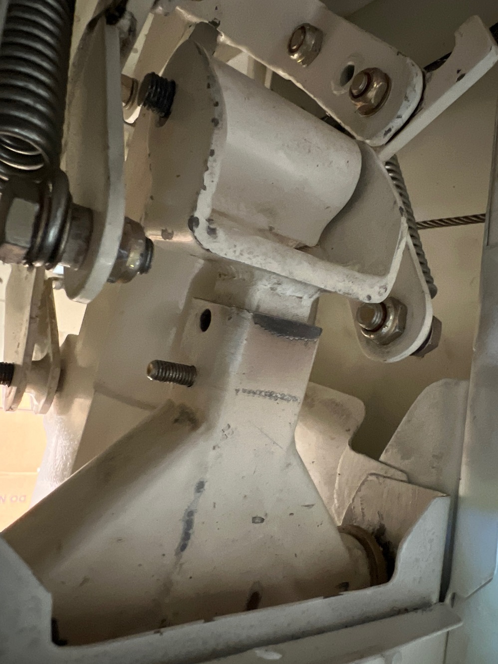
1. Bryan Update - In the last post, I discussed that Bryan went down to see the guys at AutoPSRU's and came up with a plan for his FWF setup. While he is waiting for them to work on that, Bryan got to work on making several other changes to his Prowler to his airframe. One of these is remodeling his MLG and tailwheel system. His goals are to make the system simpler and adjust the TW strut to get the optimal angle for the best taxi performance.
To get the TW right, the first step was to adjust his MLG struts (lower) to get the airplane to sit closer to a "when loaded" profile. Here is one of the MLG struts before:
In Bryan's case, he had to shorten the upper linkage of his system to get the proper strut angle. This pic shows how he determined it:And, this pic shows how much he had to remove:After that, he had to adjust his travel limit for the retract direction. He uses a "bumper" on his bulkhead flange where the brace strut moves toward as the TW retracts. This was his old bumper:Here is a new, thicker HDPE bumper that Bryan fabricated and mounted to the bulkhead flange as a travel limiter:Here is the linkage bumping up against the limiter:Here is the upper TW linkage after he shortened it. You can see the new hole and bolt he put in it to get the proper angle he needed when the TW strut was extended:
This is just a pic of the lower brace and hydraulic actuator and how it attaches to the rest of the TW linkage:
In the spirit of "KISS" here is the pile of stuff that Bryan removed from the MLG and TW operating system:
After all the work, here is a pic of the TW strut. It is from the other side (as the previous pic), but you can see that it looks much more perpendicular to the ground and tilted aft just a little bit:Nice work, Bryan! Looks great!!
2. Francis Update - The big Prowler news from France is that Francis has finished the initial construction of the center section of his plane and reached the point where he needs to put his airplane in a fuselage jig.
Francis reached out to me to ask about the jig dimensions and I have to admint, I kinda got caught flat footed! I have George's fuselage jig that I got from Ray when he was finished with it. It is currently disassembled and stored in my shed. I have not yet supported any builder that had reached this stage of their project - so I didn't immediately have any information for him.
I was able to get to work right away and and provided Francis with the necessary info to fabricate his own jig. [I cover this work below in a separate item.] Here is one quick look at his center section progress just prior to re-organizing everything so that he can get the plane into the fuselage jig:
Here is a series of pics of his
project on it's MLG and supported by an engine hoist on the aft. He is
getting ready to move the center section to position it for adding the
fuselage jig:Here is the same thing, but now he has the MLG on dollies (skates) so that he can move the whole assembly:
And, here it is in the new position that will allow him to add the fuselage jig aft of the center section:I also noticed that he has removed most of the center section fuselage above the floor and the firewall (I assume to make it easier to move into this new position for the fuselage jig):Here is some of the initial fabrication of the fuselage jig:
I believe this is a pic (below) of his new arrangement. The center section is in the "frame" that he had fabricated earlier (attached to the wing joints that allowed him to roll the center section over). He will attach the rest of the fuselage jig to this center section frame. Then, under the wing between the MLG you can see the low section of the fuselage jig. Also, in the background, you can see the vertical square tube standing up that will hold the tail at the forward rudder hinges:I can only image the amount of "moving" and "shuffling" you had to do to get your project set up in this new arrangement! That's a lot of work! Nicely done. We are all looking forward to seeing your progress as you start to add the aft fuselage to your Prowler!
Thank you for the updates, Francis!!!3. Vaughn Update - Vaughn is still working on completing his engine compartment. I just got off the phone with him and he says he's still moving metal and working on getting all of the panels formed. Here's a pic of some of his work:
He is also working on the orientation of his TW strut. Here is a picture of the work he did to install a TW locking mechanism. He was not happy with the system that was originally build onto the TW strut, so he removed it and put on his hardware:
This pic shows some repair work that he did to the skin around his TW compartment. This area got some damage during one of it's moves (prior to Vaughn buying it):
Awesome work, Vaughn. Looking forward to the final completed engine compartment!!
4. Fuselage Jig CAD Work -
There is a fixture that has been traveling around for the past 30 years that several builders have used to assemble their Prowler. We all have just referred to it as "the fuselage jig." Here is the fuselage jig with the RW&B plane in it as it was being built by Goerge and company back in the late 1980's or early 90's. Note that back then it just had a straight square tube below the fuselage from front to back:Here's another pic of the jig in storage somewhere. I'm not sure where or when this next pic is from. But, notice that the straight tube has been re-worked with a cut-out for cycling the TW on the jig in this picture (it's a little hard to see back there):I believe that later, George loaned the jig to Chuck Wescott to build his fuselage. Here is Chuck's center section mounted in the fuselage jig:
Here is a good picture of the cut-out for cycling the TW:When Chuck was finished with the jig, it went to Ray for him to complete his plane. Here's Rays plane in the jig:Suffice it to say that the fuselage jig has made it around the community. I picked up the jig from Ray down in LA when he was finished with it and it is now disassembled and stored in my shed with several other pieces of Prowler "stuff".
Above,
I mentioned that Francis contacted me and asked for information on how
to build a fuselage jig. When I realized that I did not have any of
this information, I decided that it was a rainy winter day, so I why not get right on it!?!? I went down to the shed and dug out as many of the parts that I could. Several of them are fairly long and heavy and are stored on the top shelf of some racking I have down there. But, I was able to uncover them enough, roll them around a bit and eventually get acceptable measurements of everything.
Armed with a page full of hand written dimensions, I headed back to the shop and fired up the CAD software. I drafted the fuselage jig and made the following drawings. Here is a side view:

On a little side note, since I started this Prowler Aviation work in earnest back in late 2008 (during what I call "The Big Sort"), I have always tried to do something that I refer to as "digitizing" everything. What I mean by that is this: I have tried to put everything and anything that is related to Prowler Aviation into some sort of format that I can store on my laptop - be it a jpg, pdf, bmp, rtf, xls,...and the list goes on. I also have a lot of stuff documented on paper stored in binders that I keep in the shop. But, whenever I get, make or find a piece of paper with Prowler info on it, I always scan it (or, at least, take a picture of it) and put a copy on my laptop before I file it in a binder. Being on the road (normally) more than 1/2 of every month, I have to try to be ready for a builder contacting me with a question. I always want to have all the information I need at hand so that I can answer questions as promptly as possible.
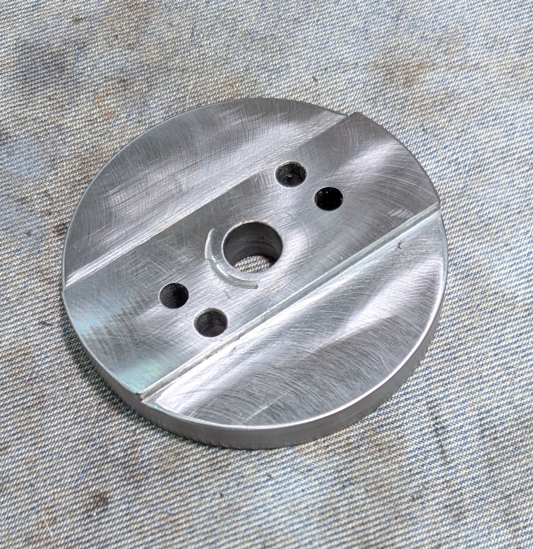
5. More Forming Dies Completed - In my push last spring to get the bulk of the forming dies cut for the Prowler, I came up short by what I thought was 5 dies. There were 4 dies that were for making the forward bulkheads on the main fuel tanks and the aft spar bulkhead that still needed to be made. When I got back into the shop this fall, these were the first items on my Prowler to-do list.
Fuel Tank Bulkheads - I decided to tackle the fuel tank bulkheads first. When I got down to doing the final CAD work to cut these dies, I discovered something I had not encountered before. I found that these dies were symmetrical about the horizontal axis! This is something that I probably should have known and comes from the fact that the wing dihedral on the Prowler is symmetric. What this means is that along the length of the wing, the axial centerline is symmetric between the upper and lower wing skin. Here's a pic of what I mean:
The Prowler wing has a 5 degree dihedral with skins 2.5 degrees above and below the centerline of the wing. Most importantly, for me, what this meant is that one die would make the part for either wing! For the first time since I started making dies, I did not have to make a separate die, one for the left wing and one for the right wing! COOL!!
So, here is what I started with - 2 patterns, 2 old inventory pieces and 2 pieces of 1" thick aluminum:
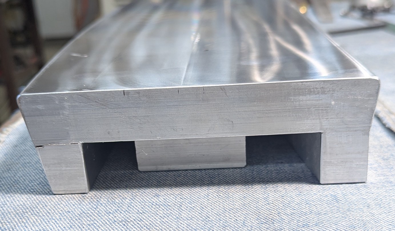
Aft Spar Bulkhead - I left this die for last, because, well ...... it was going to be the hardest! It's that simple, there is no better reason! The reasons that this die was going to be hard was two fold. First, the part has one flange (lower flange) that is 1.75" wide, which requires that the die be 2" thick (instead of the normal 1"). Then, the angle of that flange needs to be is less than 90 degrees (included angle from flange to web). This means that my normal 10 degree undercut tool was not going to work (would not be enough undercut).
Still not sure how I was going to make this all work, I got started on building the blank to make the die from. Here is a picture of what the finished bulkhead should resemble (approximately) and the 1" thick piece of aluminum plate that I started with:Here you can see where I laminated several left-over 1" thick pieces to the bottom of the main die piece (these were pieces left from cutting out nose rib dies a while ago). I just placed these "feet" so that there would be support under the full-sized piece everywhere. Remember, this has to stand up to 400 tons of pressure, so I had to cover most of the bottom with these "feet":Then, I fitted my normal fixture plate to these "feet" so that I could machine the top portions of the die along where the flanges are. Here is the fixture plate fitted onto the bottom of the die:And here is the die, ready to go into the mill for machining:The
flange along the top of this bulkhead is a normal 3/4" flange with a 90
bend angle. So, making this part of the die was pretty normal and
what I am used to. Unfortunately, I didn't think to get a pic of doing this work. I also did my "norm thing" to the edge that will form the bottom, bigger flange while I had it fixtured in the mill. I used my normal 10 deg undercut tool to just remove material, since I had it there in the mill anyway. However, I was going to have to go back and remove more material on the bottom flange, to get a larger undercut.
This is where things started to get different. So, normally, I undercut the dies by 10 deg to get a 90 angle on the flange. But, I needed about 84-85 deg bend on the big flange. So, how much undercut would be needed? The answer is - IDK? The only real way to know is to cut something - then try it. If it needs more, or less, make the change and try again. It's an iterative process.
The problem with that is, I'm cutting a die that I have about $200 into the aluminum. I don't want to just toss it, if I cut off too much. So, I had to take a conservative approach. The next question, what to cut it with? Do I really want to spend $200-300 to have a 12 degree undercut tool made (to make this one die), only to find out that it needs to be less than 12 deg?? Maybe it's only 11 deg!?!? Maybe it's 14 deg that give the best results. I really can only take a guess.
I decided that the best approach would be to look for a cheap tool that I could buy to cut it to something close to what I need and try it. If I need to make a change I will. Also, I would start with a conservative guess and hope that, if anything, I would need to cut off more and can find a different tool to do that later.
What I found was that dovetail cutters (which will give me an undercut) are relatively expensive, particularly in the size and angle of cut that I needed for this. However, I did find a tapered router bit that had an 11.5 deg angle of cut that was really inexpensive! The only thing I would have to do, is flip the die over and fixture it to the mill. Well, that's pretty easy. Look:See! Easy! So, here in this next pic is the bottom flange, upside down, and the initial cuts done to the top edge of the die (bottom in the pic) are done. Also, in this pic, I used a regular end mill to remove some material and cut the basic curve of the lower flange:And, here is the upper flange of the bulkhead which was completed normally and all I did here was use a regular end mill to remove material and recess the bottom part of the die (make it flush to the edge of the undercut):Now, back to that lower flange. Here is the 11.5 deg tapered router bit in the mill and removing some of the material off of the lower portion of the die (foot) to make it match up to the undercut that I had already put on (when the die was right side up):Here is another pic, using the 11.5 deg taper tool to sneak down to the point where the 1/8 radius (1/4 dia) tool cuts down from the top of the die. The idea here is that the 11.5 deg angle needs to start right where the 1/8 radius (round over tool) stopped cutting:
Getting closer:In the end, here is what I was shooting for:In the above pic you can see the top flange of the bulkhead (right edge in the pic) will make a normal 3/4" flange bent to a 90 deg angle. The large, lower flange (one on the left) will form an 1-3/4 flange that is bent to 84-85 deg angle. The next step is to do the CAD work to cut out a flat blank in the router, put the part blank on top of this die and then put it in the press and give it a try - to see how it works. Then, I'll make adjustments as needed. I'll report on this, hopefully, in the next update.
Here is the finished (for now) die sitting on the workbench:It was a fair amount of work, but it turned out well. I just hope, now, that it gives me the desired results on the angle of bend of the lower flange. Time will tell.
Non -Prowler Items
6. LeBlond Lathe Restoration [Mostly Done] - This is actually the first project that I worked on when I got back home this fall. I worked on this until I was waiting for paint to dry, then I'd go back to the mill and work on more dies. The first order of business with this lathe project was to get the headstock cleaned up and painted.
Headstock Repainting - The headstock was the last remaining big part of this lathe project that I still had not cleaned up and painted. This part is pretty heavy, and I needed to get to all sides of it to get it painted. So, the first thing I did was weld some uprights on the sides of the steel cart that I'd been using to hold it. Then, I welded some cradles to those uprights. After that, some 3/4" pipe through the spindle and the headstock was suspended in mid air!
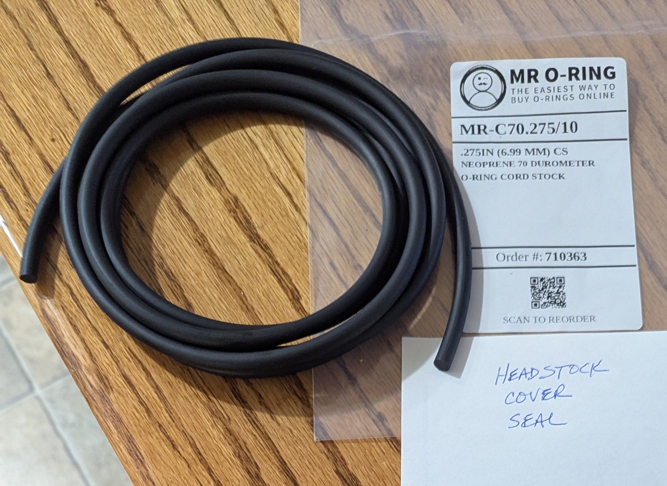
It really did make working on this part much easier to have it held up through the spindle. I could drain the oil, and get to the bottom for cleaning and stripping the old paint:I had already removed all the shifting knobs and levers last spring, so it made fast work to get to stripping the 5 old layers of paint off it. I was able to just use an angle grinder with a wire wheel cup brush to knock off most of the old paint:Eventually, I decided that I needed to take the lid off of it. However, I did not want to take any of the headstock gears or internals apart. There was no need to do that. It was all working fine as far as I could determine. But, I would need to keep the crap out of the mostly clean inside, so I placed cardboard around and stuffed the top with paper to keep the cardboard pressed tightly to the edge of the hole:I had already investigated and knew that I was going to have to replace the 83 year old cork gasket seal that holds the gear oil into the headstock. It had turned dry and brittle and I was going to have to make, or buy, something to replace that cork seal. But, for now, that was a job for another day. Right now, I wanted to get this thing stripped and primed:After stripping off all the old paint down to bare metal, I had to tape off all the places that I would not want paint on, like the lid seal gland area, placards, input and output shafts, etc. Here it is:
It's probably not visible, but I also took advantage of this time to clean up a lot of goobers on the surface of the headstock that were the result of bad casting or bad casting clean-up. There were many spots that using a small bit on a die grinder I was able to clean up and smooth them off to give a much better appearance. In any event, it looked good and was ready to prime:Primed!I used the same steps to clean up the lid. There was really only one placard to tape off:Then, strip the old paint:And, prime:Fortunately, at just the right time, we got a couple of really warm days and I was able to mix up some paint and shoot these parts outside to get them finished:
Here is the lid with a few other parts that also still needed painting:With these parts now painted, I could continue to reassemble the lathe.
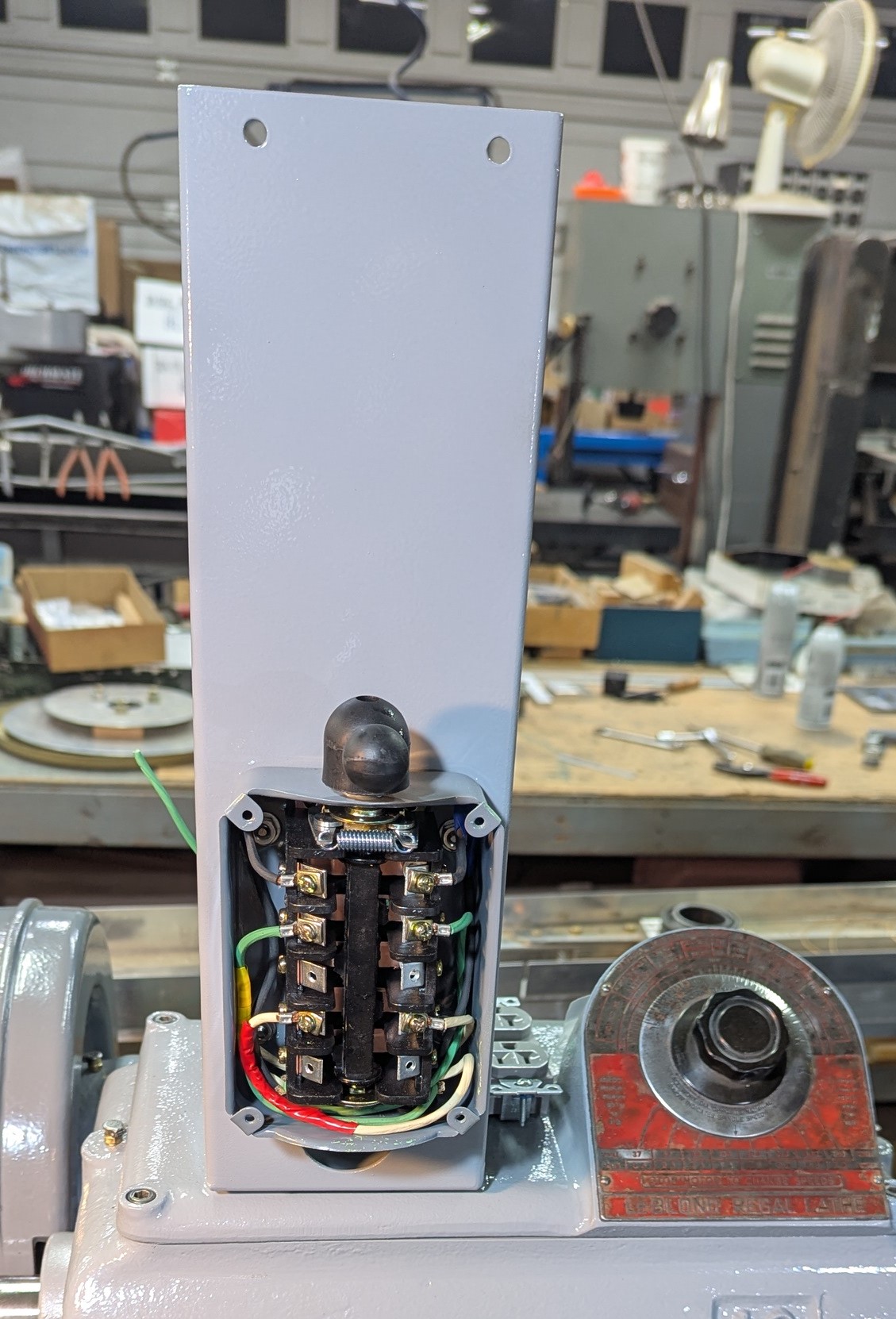
Reassembly of Major Components - By the time I painted the headstock, I had already begun to reassemble the major components on the lathe. In a previous update, I showed pics of putting the bed back on the legs and getting the carriage and tail-stock put back on the bed. Now, it was time to add the headstock back onto the bed ways (with the shift levers and knobs installed):Nice! Remember that cork seal that needed replacement? Well, it took a couple tries, but I finally found that some .275" diameter O-ring cord stock was the perfect size to squeeze into the seal gland and made a perfect fit for the lid:Next up was getting the motor re-mounted and the belt guards installed:I ended up having to do this job a few times. I made the new motor mount spacers from some pretty shabby patterns (what come on it was a mess!). So, I ended up having to modify some of the spacers a bit to get a good alignment of the motor pulley and the input shaft pulley. Eventually, it turned out very nice!:Here is the lid installed and the old motor control switch bracket attached to the top. I decided to not use the old switch. It was a HUGE water tight switch that was a 1943 US Navy requirement for this lathe and it was used to control a 3 phase motor. This lathe came to me with a 120 Vac single phase motor and I decided to keep it - at least for now. However, I would use this bracket as a convenient place to mount a new, smaller switch and install some other things....you'll see soon:Here is the belt guard, change gear cover and hand wheel all assembled and installed:Here is the new motor switch installed:I reinstalled the original electrical panel. It really did not need this, it could have all been wired without this cabinet. However, there is a cool placard on the front of the door and an old wiring diagram for the original 3 phase motor and the huge reversing switch on the inside of the cabinet door. I wanted to save this and preserve if for to maintain some of the history of the machine:
I mounted an electrical bonding strip in the old electric cabinet (above) and put a junction box(below) behind the new motor switch that would provide power outlets for the lamp and the DRO. Here is the junction box:Another pic of the wiring of the new, small, reversing switch for the 120Vac, 1 HP single phase motor:
Carriage Way Wipers - After I had reassembled the carriage onto the ways, I started coming up with some ideas for making new way wipers. The old ones were hard and crusty. I eventually found a spun wool polishing pad that I thought would work well. It did! Here is one of the wipers I made for one of the V ways (old one on the left and new one in the holder):And, this is one of the wipers for the flat way:Here is one set installed on the ends of the carriage:Notice the brass caps with the steel balls for oiling the way wipers. I'm going to have to find a good, old-school oil can! Overall, that worked out really well!
Add a DRO - As I have been working on this restoration of this lathe, I decided that I would really like to install a digital readout (DRO). I don't have anything against using magnet mounted dial indicators, but - DANG- a DRO just makes things so much easier and more convenient! So, a DRO it is.
I went online and found an eBay import system that was dirt cheap. I wasn't sure I was going to be able to fit the scales on this carriage/compound - and I didn't want to end up spending a lot of money on a brand name box - only to have to scrap the idea in the end. If a lathe isn't designed around the DRO scales, sometimes there won't be enough space to fit the scales on the carriage. When I got the shipment, I unpacked it, plugged in the two scales, plugged in the box and turned it on. It worked great!
One modification that I wanted was on the arm that the DRO box mounted to. It came with just a straight rectangular tube/arm for mounting the box. I wanted it to be articulating in the center. Here is the hinge that I fabricated from scratch and added to the arm (after cutting it half-in-two):Notice, also, that this arm is mounted to the top of the original switchbox bracket! Below, is the DRO box mounted on the end of the articulating arm:The long scale (for the Z axis) was really pretty easy to attach to the carriage. I drilled and tapped a single 10-24 socket head cap screw to mount each end of the scale to the ways. Then, I fabricated a simple bracket to mount off the bottom of the carriage and attach it to the moving part of the scale:One down, one to go. Of course, I saved the hard one for last. Is there any other way!?!?
For the X axis, I stared at the carriage and compound for many hours to come up with a plan. The first step was to make some stand-offs and a bar to mount to the compound. Here, again, I only had to drill and tap one bolt hole into the compound at each end of the bar that will hold the scale. It was a little dicey, because I did not want to drill into the gib that was on that side of the compound. There was enough material there and I measured 20 times and drilled once - it worked fine! Here is what that looked like:
This bar was going to hold the big part of the scale, but this time it would be moving. There was a convenient place on the carriage between the ways, that was pre-drilled and tapped to mount the follow rest to. I decided that I could use this to mount a bracket that would attach to the moving part of the scale (which in this application would actually be stationary - does that make sense? You'll see.) In this pic you can see the stationary bracket in the center between the two bed ways:Then, I mounted the scale. It worked - just barely! If you turn the compound, it just clears the top of the long part of the scale. But, it does work - so, good to go!Here's a pic of routing the cables for both of the scales back to the DRO:
Again, it just clears the top of the scale:Here, everything is installed and fired up. It all works great!
It literally blows my mind that for little more than 2 Benjamins you can get a 2 axis DRO that is accurate to 0.0002"! Good enough for me!
Add a Multifix - So, I have a machinist that I watch on YouTube who has a multifix tool holder on all of his lathes. They are really convenient because they have 40 positions that you can drop a tool onto the tool holder - repeatably. And, you don't have to have a large wrench to adjust it, just a small handle on the clamp. I started to research them and decided that I wanted to get one set up on my restored lathe. I was prepared to buy one of the better import sets when I ran across an old Enco set on eBay for about the same price. I went for it and got this set:
It turned out to be just what I was looking for and a fitting addition to my old, restored, American iron! These get mounted to your compound in a certain way and it was going to require that I fabricate some new pieces to fit this tool post to the LeBlond. First, I had to make a new T nut. After an hour, or so, on the mill - I had this:
Then, I needed to make a circlular plate that goes down onto the top of the slot in the compound and has a shoulder that sets down into the slot so that the plate doesn't turn/spin. Here is the start of my circular plate after I had already cut the shoulder into one side of it:I trimmed the edges and corners off in the band saw and then mounted it in the Craftsman lathe using a 1/2" bolt (that I cut the hex head off) and could mount the shank of the bolt into the headstock. This would allow me to machine it down it a nice round part:The finished product:The holes you see in the round plate are for close tolerance dowel pins that keep the main body of the tool post from rotating on this round plate. You can see these same holes in the bottom of the main body in the next pic. The reason there are two sets of holes is because on the first attempt, the lead engineer in charge of this project forgot about aligning the main body so that the number 1 position (of the 40) puts the tool holder at exactly 90 degrees to the axis of the spindle (headstock). Yeah! It's a thing!
This is the main body of the multifix tool post that will clamp down onto the top of that round plate:I had to make a special shoulder bolt that would hold it all together, like this:
Here it is, with everything mounted into the compound on the lathe:It was at this point that I noticed the clamp shell wasn't holding itself around the main body of the multifix very well. I took it apart and found this:It looked like the pin had some kind of head on it that had been broken off. I contacted PeeWee Tools in Germany (Peter is the expert in multifix quick change tool posts!) He sent me a drawing of what that pin should look like. He said that he had some in stock, but when I tried to order them, I was having problems. So, I just decided to make my own. Here is my reference drawing (with my finished pin in the center):
I made my pin from a small grade 8 bolt and here it is in the clamp shell with the spring:
Put back together:What that pin does is put a small force on the sides of the clamp arms to keep them lightly clamped around the main body via the spring pressure. Here it is installed back on the tool post:Now, it is all working great!Here I am checking the alignment of the tool to the center of the spindle. Looking good!A little later, I order a few more tool holders from Peter and a clamp handle (my eBay sale did not come with the handle). Here are all my tool holders and parts for the multifix:And, the new tool holders fit perfectly onto the old multifix main body - and the clamp handle works great:It's gonna work great! At this point I am pretty much done with this restoration. I can't wait to finish the set up of this lathe (moving into place and leveling it) so that I can cut some metal!
I still have to clean up and paint the steady rest and the follow rest. I will get to that once the weather warms up and I can paint again. The only other thing that I might want to do is add some kind of a coolant system to it, but for now, I will call it a wrap!
Lathe History - I went and found the LeBlond website recently and submitted a request for information about my lathe. You just give them your contact info and the serial number of your lathe. The next day, they returned this to me:Well, it looks like the 82 year old microfiche has seen better days! However, I was able to stare at this thing long enough while changing the contrast, change the lighting, zoom in, zoom out, etc., etc. and get some useful information about it.
This lathe was sold the the US Navy on 21APR1943 and was promised to be completed by 30APR1944. It was shipped to Consolidated Steel Corporation, Shipbuilding Division, Orange, TX on 12JAN1944! That is pretty cool! WWII was going on when this lathe was built and delivered to the Navy!
I dug around to see what ship that this lathe might have been installed on, but the best that I could find is that at the time of delivery of my lathe to Consolidated, they were under contract to build two warships for the Navy. One was for about 27 Gearing Class Destroyers and the other was for about the same number of John C. Butler Class Destroyer Escorts.
So, chances are good that this lathe was installed on a ship of one of those two classes. But, there is really no way for me to find out any more detailed information. It's doubtful that Consolidated kept records of what lathe was installed on what ship. And, if they did, that information was likely lost decades ago when the company closed.
What would be even harder to follow is how the lathe got off of one of those ships before it was sold to a foreign country (many were), or before it was sunk as a target during bombing practice (which, also, many were!). More interesting still, is how that lathe eventually made its way to the north state of CA and into the hands of the old-timer that gave it to me!?!? I will probably never know, but it is interesting to speculate and to know what history that I have now!
Here is the best, current, overall pic that I have of my "new" lathe:
I really have it wedged in between a bunch of other machines and stuff,
so it's hard to get a decent picture. But, for now, it will have to do. So far, I am really happy with how it has turned out. Looking forward to making my first chips with it soon!
7. Yamaha Golf Cart Upgrades - I have this old golf cart that I use around the property to haul stuff around, to run up & down the hill to the shed, to run get the mail sometimes and to spray weeds in the spring. I put a bunch of my original repair work on this machine in blog updates many years ago. Ever since I got it running and put back together, it has smoked while running - a lot! I figured it was either from worn or broken piston rings or from a worn out seal on the intake valve stem (from what I gathered off of the internet forums). Lately, it seemed to be getting worse. Anyway, I have planned to do an engine overhaul on it for a long time.
Well, that time came a few weeks ago. I found a place online to order a good overhaul kit for that Yamaha engine and I ordered it with a new set of wheels (the old ones that came with it were pretty much junk back then - and that was 10 years ago!). When the weather guessers recently forecast a week of rain, I pulled the car into the shop and took off the junk box, the seat and back rests, the main body cover and then..... pulled the engine. Here is the supervisor strenuously objecting to the loss of his golf cart usage (Whiskey loves his golf car rides!):
Here is the motor as I pulled it out of the cart:It needed a lot of cleaning. I found a huge mouse nest built up in between the cylinder and the air flow baffles which I am sure was not good for cylinder cooling!Before the overhaul, the cart did not like to start right away. You would always have to tease the pedal to get the spark igniter box to light off. I think I found out why! The pick up coil on the back side of the flywheel/fan was covered in dirt, dust and rust!
There was also rust on the surface of the magnet that passed by this pickup coil (located on the back side of the finned flywheel). Turns out, after cleaning these up, the cart does start much better now! Rust and other junk on these surfaces scatters the magnetic field (magnetic flux lines are not uniform and densely packed). This weakens the system and the pickup coil cannot make as good of a signal. [The exact same thing happens to magnetos on your lawn mower or other small engines. If your lawn mower is hard to start, take it apart, sand off the magnet and the ends and the magneto pickup coil, then re-gap the magneto and put it back together. You'll see a vast improvement!]
Here is the top of the cylinder head: The intake valve is on the right. The culprit seal (that leaks and causes the oily blue smoke when the engine is running) is inside/under the spring and around that valve stem:Here is the inside of the crankcase. One of those two gears turn the cam shaft and the other turns the counter balance. The narrow pointy thing is the oil splasher that kicks oil all over inside the crankcase to keep everything lubricated:
Here is everything put back together after the rebuild. It's all pretty straight forward and I just used the Yamaha Service Manual and watched a couple YouTube videos to make sure I got everything back together properly. There are a few tricks, so it was good to watch the videos in advance, before tearing into the engine. It's ready to go back into the car:At one point, I was still waiting for one specialty tool to show up (order the primary clutch/sheave removal tool at the same time you order the rebuild kit - it'll save you some time waiting for Amazon to bring it to you later). And, you will not be able to finish the teardown and get into the crankcase until you remove that sheave off the end of the crankshaft. Anyway, since I was waiting, I decided to put on the new wheels that had gotten delivered a few days earlier. Whiskey approved the new mounts, so I put them on:There! Much better!A few days later I got the tool, got engine rebuilt and installed it back into the car. Here it is with the junk box back on and ready to go.
So far, it was a successful overhaul. The smoking has stopped completely and it runs a bit better. It has a little more power climbing hills and Whiskey reports higher ground speeds on the flat and level runs - his ears fly higher in the slipstream! After a few hours of break-in time, I'll drop the oil one more time and top it back off. This buggy should be ready to go for a few more years!
8. 2016 Subaru Repairs - Mrs. Prowler Guy hit a deer on the way to work last fall:It
did a number on the bumper cover, grill and pax side headlight, but
fortunately (unbelievably) no metal got bent! So, I figured it'd be a fairly simple
repair job, just replacing a bunch of plastic. So, I got online and found cheap replacement bumper cover (primed, but not painted). I went down to the shed and found the stand that George built to hold the outer wing panels and strung the new bumper cover up onto it:I used a combination of wood and wire to hold the thing suspended so that I could paint it when we got a warm winter day.That day came in mid Jan when it got up to nearly 70F on a couple days. So, I got the paint on it. I purchased the paint from local vendor. You just take them the paint code and they mix up a pint and give you all the reducer, hardener and adhesion promoter, etc.It looks OK from a distance, but I am definitely no auto painter!!! But, this thing is going on a 10 year old car with nearly 200K miles on it, so.....close enough is good enough!!
After the new headlights and grille showed up, we put it all back together. It turned out pretty decent for a quick fix, shade tree mechanic deal.On to the next project!
9. New Street Number Sign - This is something that I've wanted to do for a long time, but just always had something more important on the priority list. I finally decided that I wanted to get it done, even though I probably still had more import stuff to do. I made up the CAD and CAM files to cut the numbers out of a sheet of aluminum. Then, I found a piece of 3/16" steel plate to mount them onto:Of course, the time consuming part of this whole project was dealing with the centers of the 8 and the 0 (zero). I ended up just using countersunk screws tapped into the steel plate to hold them in place (I didn't want there to be "tabs" to hold them that you could still see from a distance). Anyway, with that fitted, I removed the numbers and fabricated the rest of the post and welded the steel plate unto it:On another warm day, I mixed up some concrete and put some anchors into the ground to hold the post in place. I used three 1/2" bolts sticking out of the concrete in a triangular patter to hold the plate that I had welded to the bottom of the post:Whiskey approved the installation - so I finished it up with a couple coats of paint and then re-installed the numbers. Overall, it turned out pretty nice. A lot better than the old post with the numbers nailed onto it (on the left):Next!
10. A Custom Wave Runner Trailer - My neighbor's adult son is a truck driver. He recently bought a new SeaDoo Wave Runner and needed a trailer for it. He is on the road a lot, of course, and my neighbor wanted to surprise his son with a trailer for his SeaDoo.
I had this old axle laying around and figured we could put it to use! Here is the axle as I was re-installing the spring after some cleaning, painting:
Here are the tail light brackets I made on a rainy day when I couldn't work outside:When the rain stopped, I got outside and welded up a frame for the trailer. Here it is after installing it on the axle assembly:(And, it was after we got the new wheel bearings and new wheels on the axle.)
With the basic frame completed, we next installed the hand winch, tongue jack and chains:Here it is upside down at my neighbor's shop ready for the final paint job. He wanted to paint the underside first. Later, we flipped it right side up and he finished the painting and wiring.I don't actually have a pic of the finished trailer with the wave runner on it. But, here is one with the machine on it when we were deciding where and how to mount the padded rails onto it:
It turned out really nice, and he now has a one of a kind trailer for his SeaDoo!!
Well, that's all for this update. I hope you are all off to a great start in 2025 and enjoying the spring weather! I will endeavor to get another update completed before AirVenture 2025.