In this update:
1. Hydraulic Press
2. Bridgeport Mill
3. CNC Plasma Table
4. Builder Reports
Before we get started, just a few thoughts on where Prowler Aviation is today and where we hope to go in the future. In this update we will cover several facets of building our capability to manufacture parts for constructing our first Prowler. Our plan is to develop and use these processes to make most of the parts for our first company aircraft. By going through the aircraft one subkit at a time, we will eventually have the capability to produce most of the airframe.
Once that is complete, we will have the knowledge necessary to make the aircraft in (at least) one manner. From there we will be able to consider larger scale production and how we want to accomplish that. There will be many options and we will consider as many as possible to come up with a practical, economical, scalable and reliable way to produce airframes.
We plan to put one of George's engine designs onto our aircraft, but we currently do not plan to offer the engine for sale with the kit. We've decided to limit our scope (at least initially) to producing the airframe and save the firewall forward for later. We will also have (for the first time ever) complete, accurate and thorough documentation of the aircraft. This documentation will include a shop manual (how to build each subkit), the builder's manual system (how to assemble the subkits into an aircraft), a complete parts list spreadsheet, a virtual computer model of the Prowler, and a business plan.
That's the long term plan. If you've been keeping tabs on us in this blog, you'll see that we've made significant progress on several of these areas. Most of this update will discuss progress on the manufacturing of parts. Last summer we completed the "big sort" and did much of the parts list work. Modeling of the airplane's parts will happen as we make the parts for our airplane. The CNC plasma system is almost ready - as you'll see later in the update. The builders manual system will also be accomplished as we build the airplane, subkit by subkit. Two of the subkits shop manual parts have been completed and the rest will be done as the plane progresses. The business plan will be the last task to be accomplished.
Our airplane currently has most of the wing spar parts (center and outboard) made. The spar is currently waiting on the cutting of a few parts with the CNC plasma system. We have the vert stab subkit built. The current goal is to make up the horizontal stab subkit, get the needed wing spar parts made, get the wing spar installed to the wing jig and press out the wing ribs by the end of the year.
So, there it is. We hope this helps to outline where we are here at Prowler Aviation. On to the update.
1. Hydraulic Press - To reach the goal of getting wing ribs pressed out by fall - a press would be helpful. So, this past two weeks we fabricated the hydraulic pump unit and installed it onto the press. The hydraulic ram had been refurb'ed previously and the pump unit was hooked up to it. We added a 40 amp 220volt circuit and a motor controller and presto - hydraulic press. Here's the pic:

 The hydraulic pump is only good for 1500psi. However, the piston in the ram is 5 inches in diameter and that gives an area of approximately 19.6 square inches. This gives almost 30,000 lbs of pressure from the ram. Spread that force out over an average part area of 300 square inches and it figures out to about 100psi. Should be more than sufficient to fold up some 0.040" type O aluminum. Next comes the learning curve associated with actually pressing out parts. In particular, keeping the male and female dies lined up with the flat blank that will become the part as the press does its thing. More to follow.
2. Bridgeport Mill - It took a while to get the mill cleaned up and order some parts needed to fix up the mill a bit. The most interesting was replacing some head bolts. One was broken and one was beat up a bit. The change was fun:


 We got the mill moved into position, hooked up with 3 phase power and have even used it already to machine some slotted holes into some brackets for the CNC table. The 3 phase power comes from a rotary phase converter. We purchased a phase converter panel from Wyn Phase Converter and Supply (http://www.wnysupply.com/index.cfm) and scavenged a 3hp idler motor out of an old air handling unit from the local industrial surplus place.
 We had a little problem with the delivery of the phase converter panel. Apparently some components shook loose during shipping and managed to beat-up the rest of the components in the panel along the way. Here's what it looked like at delivery:
 Not wanting to wait the time that would be necessary to return it and wait for a new delivery, we set out to put the pieces back together. With the help of screws, glues and bailing wire we got it put back together and installed. It turned out well. Total cost for the phase converter was ~ $200. Here's a shot of the final rotary phase converter install:
 Here's the mill pretty much ready to go:

3. CNC Plasma Table - This project has been a long time in the works, but it will hopefully be the centerpiece in being able to practically and efficiently cut parts for the airplane. We've determined that upwards of 80-90% of the parts for the airframe are made from flat pieces of raw stock. After a bunch of research we decided to pursue this process as a means to make our parts. After more research we found that to use a plasma system to cut thin material requires a system that can automatically control the height of the torch. This provides the best cuts, maximizes the life of consumables and prevents wasting raw materials. To that end, we needed to make several modifications to our CNC table and torch systems to get the best chance of getting good parts. We've covered most of these in previous updates and are getting close to the big "first cut." The latest mod was to replace the signal generator (2-D box) that came with the Torchmate system with a new box (MP3000) that has 3-D control and auto torch height control. In fact, it's digital torch height control that is fully integrated with the X, Y, and Z motions axises.
 This box also, however, requires the use of a new software control system to control the table motion. You can check out the box details here: http://www.candcnc.com/ Look for Digital Torch Height Control. The software is Mach3 and it is an open source software that CandCNC has optimized for use with it's MP3000 system. You can check it out here: http://www.machsupport.com/.
Overall, the modification has been pretty straightforward. The hardest parts were actually installing the Mach3 software and getting it to run on the computer (various issues) and getting the new MP3000 box to interface with the Torchmate supplied motor controller box. We could have just bought new motors, controllers, power supply, etc. from CandCNC, but in an effort to get the lowest cost system possible, we wanted to use as much of the Torchmate system as possible. With enough research and help from CandCNC we were able to figure out the correct translation of wires to get the two boxes to work together. A quick re-wiring of the female DB-25 connector in the Torchmate motor controller box allowed the use of a simple 25 wire parallel computer cable to hook the boxes together. The box and software are installed and the table is working in all three axis's
 We also installed the digital torch height control system, but so far the test has been unsuccessful. Didn't have time to troubleshoot further before having to head off to the day job for the week. More to follow. We also made several "tweaks" to the CNC table to improve the accuracy. These included adding bracing,
 re-mounting the X axis motor and shafting,
 re-meshing the X axis rack and pinion gearing,
 and adding more Y axis cam followers to support the new floating torch holder. Here's the slotted bracket mods to the Y axis carriage plate for the cam followers to be added to.
 All these mods have greatly increased the rigidity of the CNC table which will ultimately lead to much more accurate parts. Unfortunately, we didn't get a pic of the overall CNC table with all the new mods. We'll post one next time.
4. Builder's Updates - A lot to report here too.
Kit #1 & Kit #13 - Rick has updated his Prowler site and moved it to a new web address. Check it out here: http://www.prowlerjaguar.com/
Kit #5 - Currently owned by George Morse. It is still for sale. You can see pix of this aircraft on Rick's site (above). We did an engine run-up recently and all is running well.
Kit #7 - Bryan's work continues.
Kit #10 - Ray has installed all the autopilot servos, gotten a new hydraulic accumulator, and cut his instrument panel and cut holes in his side panels for instruments. On the last visit, we dissected and spec'd out the propeller spinner and the radiators. Thanks Ray, nice work!
Kit #11 - Ben has opted out of the Prowler program. Cabi is brokering a deal to purchase Ben's kit and ship it to a new owner in France! In the next update we'll be introducing the new owner. The Prowler has gone global!
Kit #12 - Ray sent the following update on Chuck and his Prowler. In Ray's words: "Chuck flew first flight #2 this weekend. He said the plane handled well and the gear retraction went right. Chuck said the flight only got around the pattern once, the coolant temp went back up to 240 again, just like the last time, and the low oil qty light flickered. George said he didn't have any ideas about the coolant temp, but the oil might be low, and raise the quantity to 12 qts instead of 10 because there is a lot of oil trapped in the accessory case and almost as much in the prop and gear box." We are happy for your partial success Chuck!
Kit #13 - See Kit #1 above.
Kit #14 - We just found the following comments that Steve left after a recent blog update. Here it is in his words: " Hey Todd and company, Thanks for the news. I was able to test fly my airplane #14 late last November and I'm happy to report that my cooling issues are solved. 1.6 hour flight, no squawks.I cut a 4" by 5" square hole near the back lower corner of each of the small removable cowls that cover the exhaust pipes and covered them with stainless steel louvers. These allow air to exit the cowl, which draws air through the forward oil cooler, around the pan and out, and also allows the hot air coming out of the supercharger waste gate to exhaust overboard. The oil temp stabilized between 180 and 200 degrees, and was controllable with the cooler door on the aft cooler.I'm now just waiting for good weather in the pacific northwest to continue flight testing. More news to follow in early spring." Congrats and thanks for the update Steve.
Kit #16 - Bud has been working on tailwheel issues. We're planning a visit to meet him and see the plane later this summer. We'll update then.
Kit #17 - As mentioned above, Cabi has been brokering a deal with Ben's former kit. He also a some exciting news that we'll be able to tell you about in the next update.
Kit #18 - WYSIWYG!
Well, that's it for this update. There is always more, but it's almost 11pm with an early 4:30 wakeup tomorrow. Hope you have enjoyed the new info. Thanks for stopping by to check up on us! Happy Easter to all.


 Now we just need to purchase some new tips and consumables for the machine torch. Hypertherm is making a new line of consumables that they call their "Thin Cut" tips. They have been having good success with these tips and they have apparently been getting good reviews from customers. More on that when we get the machine cutting some metal.
 In addition to this setup, we spent a day plumbing compressed air to the other side of the shop to supply the air to this cart. Another day was spent running an 8 gauge 40 amp electrical circuit over to the other side of the shop to supply power to the plasma torch.
 3. Floating Torch Holder - In preparation for adding the automatic torch height control, we need to have a floating torch holder. These are for sale online, but some cost as much as $1700. Using ideas gathered from several designs found online, we put together our own torch holder. Here are some pics of the assembly.


 Just before leaving for work this last time the UPS truck delivered the leadscrew and stepper motor that will do the Z axis movement. Here's a rough idea of how the leadscrew will be placed into the unit:
 Once we finish the torch holder the next step will be to purchase the auto height control electronics and software and convert our TM1 table to a Mach3 table. We'll still use the TM motor control box, but it will now be controlled by the Mach3 software. This setup will give us true, digital, full 3D toolcut path capability (and arc voltage height control). More to follow on this.

 Overall, it seems that the mill is in great condition for the price - with just a few minor repairs (and a good cleaning) needed. So far we've spent a day cleaning the lower part of the mill, lubricating the ways, and getting the DRO (digital read out) to work. The DRO sensors were very dirty and needed alignment, but now work great. This tool will be invaluable in producing parts for our first aircraft and is a necessity for making the accessory gear drive and PSRU parts for the engine. More to follow.


 Great work Bud! We also got Bud hooked up with our Yahoo Prowlerbuildersgroup and look forward to learning a lot from him on building the Prowler. Congrats Bud and we are all looking forward to your first flight. Thanks for joining the group.

 See Rick's website link (on the right side bar) for more information. We look forward to working with you and assisting you in getting your aircraft back together and kit built. We will post more about his plans once he gets his inventory done and has had an opportunity to come up with a game plan. Welcome aboard Rick.
 Cable guides are now installed and table tested. No more wires hanging off the ceiling!! The torch holder system mod is up next. Here's the "manual" torch holder before removal:
 We are investigating modifying this to a "machine" torch holder that will also be able to be used with the torch height control system. More to follow. Here's a pic of the current setup:

 We found a day we both had some time and I went to visit him. We spent the better part of a day trying to flatten the "learning curve" on using his setup. The parts are still being worked on, but after seeing his machine work I realized that this is the way to go - when it comes to producing Prowler parts.


 The table came with the computer setup, but has had the hard drive reformated and a new operating system installed. The monitor has been replaced with an LCD monitor. We still have a lot more work to do before this becomes a useful tool in the Prowler shop. First off, we still have to purchase a plasma torch for it. I have been trying to learn how to use the software and I'm having some modest success. I have modeled my own "sample" part using the Torchmate CAD software. I have exported this file from the CAD software as a .dxf and then imported it into the Torchmate software that actually runs the machine. This software converts the "sample" part .dxf file into something called "G-code" which is what actaully makes the table move in the correct way to cut the part.

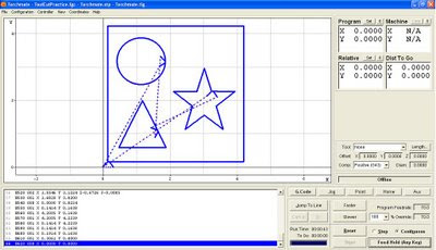 When we get ready to make another airframe, it should simply be a matter of putting the metal in the machine, pull up the files, and hit enter. Without having done any in-depth research, the hope is that we (using our system and Cabi's system) will be able to satisfy our production requirements - when we get to the point where we can start selling airframes.


 Also, the pieces were scribed to the pattern and then cut just outside of the scribe lines. This leaves enough material to file down the edges to a smooth finish. Turns out this represents a lot of filing. So, on to a better way.
 2) Cut two 1/4" spacer strips for each pattern. One spacer strip goes under the entire stack and provides room to have a counter-sunk bolt head. The other is to provide room between the roller bearing (that rides on the pattern) and the actual cutting part of the bit . This keeps the pattern a good distance from the cutting edges and prevents chewing up he pattern. See pic in item 4 below.
 4) bolt the "stack" together and adjust the router depth to get the correct height for the pattern to ride on the roller-bearing:

 5) Make a
 The next item to work on are the bearing blocks. They are rectangular blocks that surround the bearing and are clamped under the wing attach brackets.

 By mounting the drill deck (table) under the bench top the drill can just penetrate into the bench top and (most importantly) the head of the drill press is now height adjustable above the bench top buy loosening the drill deck handle and adjusting it.
 Make sure to square the head of the drill press to the bench top. We used a

 Vertical Stabilizer Sub-Kit - Armed with the new spreadsheets, we now have an idea of what inventory items currently exists in each sub-kit and what we will need to fabricate to complete an airplane. The first sub-kit on the list was the vertical stabilizer. Turns out that we had all but about 4 parts we needed to


 Once that was done we drilled the skin and built a crate to ship it to the "
 Now it's on to the fabricatiion and
 This is the steel sheets, steel tubing, bearings, hardware, etc., needed to assemble the Tail Group Sub-Kits and the Wing Group 1 Sub-kits. Hard to believe, or maybe not, that including shipping this pile of stuff represents over $1K worth of materials. In some cases there is enough material to make more than 1 airplane, but some things have to be bought in a minimum order - so that's what ya get.