Monday, March 12, 2012

Prowler Kit #13 For Sale

This is a special blog post dedicated to Roy's Prowler Kit #13.  Roy is forced to sell his airplane, and I thought posting the information here might help him accomplish this.
Here are some of Roy's Comments:

 Ron Chamblin from Jacksonville, Fla.  purchased kit #13 in the mid 1980’s after seeing the prototype at Oshkosh.  He was advised (full-time) by an A&P to help him build it.   After 5 years of full time work, he was getting tired of working on it.  The orignal Prowler Aviation had closed its doors and Jaguar #1 (the kit prototype) came up for sale.  Ron then also bought the 1st company aircraft (the RW&B airplane).

Work began to repair the RW&B but was halted at some point, and no one seems to know why.  Both aircraft sat idle in Ron's shop/barn for many years untouched. I had contacted him a few times about buying the kit but he would not sell.

A few years later Rick Pellicciotti (from Memphis) was able to strike a deal with Ron to purchase all the Prowler/Jaguar stuff that he had.   Rick really wanted Jaguar 1 and will be restoring it to flying condition.  I eventually purchased kit 13 from Rick.

This is a unique and interesting airplane. It is for the serious builder as there will be some fabrication required. What you see is what you get. There are numerous parts that are missing and/or were never supplied.  Except for the fairings and inner gear doors, the basic airframe is there and mostly complete.   Just add engine, instruments and go fly!

I have not touched the airplane except to put it together so I could look at it and drool.  Here is what is included with Prowler Kit #13:
  • Ailerons are completed.
  • Flaps are completed (see note below).
  • Vertical Tail is completed.
  • Rudder is completed.
  • Horizontal Stabilizer is completed.
  • Elevators are completed.
  • Fuselage is mostly completed from the firewall aft. Landing gear, including the retractable tail wheel is installed. Most of the hard line hydraulic plumbing is complete, but no hydraulic cylinders or hydraulic hoses. The hydraulic pump is installed. There is also a lot of wiring already in place.
  • The outer wings are mostly completed. The top skin riveting is not complete since there is some fuel tank work that still needs to be completed.
  • The Radiator Assemblies are mostly complete.
  • Canopy and Windshield are included.
  • Canopy frame included.
  • Elevator Push Pull Tube included.
  • A few boxes of assorted parts.
NOTE: There are two damaged spots that were on the airplane when I purchased it. 1st spot - One of the flaps has a dent in the trailing edge. I was going to re-skin the flap, but several people tell me they would cut it out, patch it, and then fill it so it doesn’t show. Skinning the flap is my choice and not that big of a deal.  2nd spot - There is damage on the lower fuselage at the tail wheel retract area. It looks to me like the tail wheel (at some time) unlocked and retracted into the wheel well.  Maybe when it was being moved or something.  It has caused a crack about 1 ½" long on both sides of the wheel well cutout.  My plan was to cut this area out and make an access panel. It’s a simple fix and would provide better access to the tail wheel retraction mechanism for inspection and maintenance.

Here are several pictures of the airplane to view.  I will be glad to take any additional pictures you would like and send them to you.  My name is Roy.  Please send me an email at: 
(insert my first name here)farris1(_at_)comcast(_dot_)net.


If you are unable to contact Roy at the email address above, you can contact me at the Prowler Feedback Contact Page (HERE) and I will forward your message/information to Roy.

If you are interested (or know someone interested) in a Prowler project that is off to (what appears to be) a great start - contact Roy.  Thanks.

Friday, March 9, 2012

Press Brake Success! Spar Parts Complete.

Hello Again,

Thanks for stopping by to check on the progress here.

Well, after many tweaks, lots of calibration and then more testing - I've finally found success bending 2024-T3 with the press brake that we built last March.  Now, with the ability to cut out parts with the MotionMaster router and then bend them with the press brake, I finally have the processes in place to make many of the airplane's parts.  This includes any part that is cut from flat stock and then has any kind of straight flanges or bends required to complete the part.

This capability allows me to make all of the aluminum main spar parts (both center and outboard sections), and most of the steel main spar parts.  Part of this update includes the set-up of my Ganesh CNC 3 Axis Mill that will allow me to make the 4130 steel parts that I need to build the main spar.  Shortly, I will have the all of the spar parts I need to assemble the entire main spar and install it in the wing jig.

When I do get the main spar installed in the jig, my focus will shift to buying and/or building the machines to give me production capability for the airplane parts that I need to made using the rubber-hydroforming process that I've mentioned in previous posts.  Of course, progress on the airplane will (necessarily) slow down a lot while I work on these rubber pressing projects.  But, once complete, I will have the ability to press out my wing ribs, install them onto the wing spar, and continue to build the wing structure.

The capability to press these parts will also mark the time when I have production capability for most of the airplane - the only notable exception being the majority of the landing gear parts.  Historically, the landing gear gets installed after the wing is completed in the jig.  The center section gets removed from the jig, flipped upside-down on the cockpit floor and then the landing gear is installed onto the torque box torque tubes.  Since I have a while yet before the wing is complete, there is time to to contemplate the production of landing gear parts.

OK, that's the very short term, short term, and medium-term future plan/goals here.  But, now, let me catch you up on what I've been up to in the past 3-4 weeks.  In this update:

Press Brake Back-Gauge Completion
Press Brake Calibration
Outboard Wing Spar Channels
Center & Outboard Skin Flanges and Bridge Shims
Wing Rib Attach Angles
Ganesh GMV-2 CNC 3 Axis Knee Mill Set-up
Builder Updates
   Ray,Chuck & Bud
   Bryan
   Roy - Kit 13 For Sale
Press Brake Back-Gauge Completion -  The flanges on most parts are uniform in width, so I wanted to have a convenient way to set the width of the flange for pressing.  I came up with this system that allows me to quickly set the flange width.  This pic shows the set-up out of the press:
 With the distances involved, I had to add a "spacer" to be able to get the scales placed in an acceptable area.  So, I riveted an aluminum angle to the back side of the back-gauge.  Once installed in the press, and after a few test bends, I was able to accurately calibrate the counter-sunk scales.
Here's a overview of the whole assembly out of the press:

Press Brake Calibration -  In a previous post, I outlined the beginning of the press brake calibration and bending of  test strips.  During that time  I found that I could not just bend clips at each end of the lower die beam, but to get more accurate results I also had to have a piece in the center of the die.  So, I started bending sets of 3 pieces and trying various plunge depths.  As I did this, I noticed a few things that were affecting the consistency of the bend angles.  First, I determined that using the hydraulic system (that I outlined in a previous post) was causing variability because it was essentially "overkill."  The hydraulic rams were pushing on the stop blocks too much and flexing the entire press brake - producing inconsistencies.
The second thing I noticed was that I was getting some strange warping of the parts that I was bending.  I wasn't sure if that was because of the press brake, or the material.  I suspected that is was the material causing this warping, because it was SO uniform.  I figured that the press brake couldn't be doing this so perfectly uniformly.  Here's a CAD drawing that simulates the warping that I was seeing:
In an effort to figure this out, I found a website called www.homebuiltairplanes.com that has a sheet metal forum for questions.  I posted on this site and eventually got some great feedback that did help explain what what happening.  Turns out that this warping is called "cambering" and IT IS a function of the material.  As the material gets stretched and compressed along the bend line, it causes this warping to happen.  You can check out this link to the thread for more info.

Armed with this knowledge, I found a way to deal with this deformation and was finally ready to try some long pieces in the brake.  I decided to start on some 2" ID channels, since there are many of these in the airplane and if I messed them up too bad, I wouldn't be wasting too much money.  By the time I completed the third channel the bends were coming out pretty nice.  Here's a pic of the first two channels lying on the mat and looking down the edge of the 3rd channel :
By the time I'd gotten the third channel bent up satisfactorily, I got brave enough to try one of the outboard wing spar channels.  That's next.

Outboard Wing Spar Channels -    Here's the first spar channel in the press:
Here you can see the finished product - fresh from the press brake and with the long spar cap strips installed onto the channels. They came out great.

This was a big turning point for me in the quest to re-establish some limited production for Prowler Aviation.  It gave me a lot of satisfaction and motivation.   A lot of what I've been working on for many years now is represented in these two parts.  I've actually been working on a satisfactory way to bend these long pieces for over 3 years - starting with the unsuccessful attempts to repair and modify the 8 foot sheet metal leaf brake.

So, completion of these outboard wing spar channels was REALLY noteworthy because:
1. They were cut from G-code that came from the CAD drawings that I've been working on for over 2 years;
2. They were cut in the MotionMonster CNC router that I'd spent much of last year repairing, modifying and installing in the shop. And;
3. The were bent in the one-of-a-kind, purpose built press brake that my dad and I designed and built while he was visiting last March.

This was a pretty sweet success!

Center & Outboard Skin Flanges, and Bridge Shims - Energized by the success with the spar channels, I moved on to the wing spar skin flanges.  Here are the forward skin flanges for the center section.
Here are the aft skin flanges for the center section of the main wing spar:
The next parts on the "To Do" list were the spacers that fit between the upper and lower spar cap strips under the wing rib flanges (both on the center section and the outboard sections).  Here is a shot of one set of these spacers in the mill getting machined down to size:
Here's the entire set of the spacers:

Wing Rib Attach Angles -  The last of the aluminum parts that I needed to fabricate were the angle clips used to mount the wing ribs to the main spar.  Since I don't have a sheet metal shear (yet), I used the MotionMonster to cut some 1-3/4" strips from a 4' piece of 0.050" aluminum (on the right in the picture below).  The parts in the middle (below) are specially shaped rib attach angles that go on the inboard rib of the outboard wing section.  The piece on the left is for the wing pylon attach points (that is actually left-over stock from George, so I didn't need to fabricate that piece).
Once I got the stock cut into strips, it was time to cut the strips to the correct lengths:
Then, bending in the press brake was next:
Here's the completed parts after bending in the press brake.
The bends are coming out very nice - correct angle (90 deg) and uniform over the length of the angle:

 Ganesh GMV-2 CNC 3 Axis Knee Mill Set-up -  So, with all of the aluminum parts of the spar complete, the only parts left to make for the spar are steel parts.  These parts are made from 4130 chromoly steel.  Because the forces involved in cutting the steel go up, they require a bit more fixturing to hold them while cutting.  The vacuum table on the router isn't capable of holding the material for these parts - so it is time to get the CNC mill running.  The first task was to find a place to put it in the shop.  The shop is starting to get full.  But, I decided to take a day and move the mill into a position near the Bridgeport manual mill - since I have the 3phase power there, a lot of the tooling there, and it's closer to the workbench (I can't tell you how many 60 foot round trips I made to the workbench while setting up the MotionMonster!)  So here's a pic taken just after rolling the CNC mill into position with 3/4" pipe.
Next was getting power set up to the machine.  Here's a switch box that I wired up to turn on power to part of the machine:
Here is a picture of the machine in it's new home spot in the shop:
This is a close up view of the controller on the CNC mill.  It is (coincidentally) made by the same company that made the controller for the MotionMonster - only a few generations newer.  The router has the Fagor 8025M controller and the CNC mill has the Fagor 8040M controller.  This is a much more capable controller, but it is also going to take a bit longer to learn how to use - it seems.  Here's an older file photo:
Once I got the machine powered up again, I went to work getting it hooked up to a laptop computer.  After a little messing around, I got the machine to sync with the laptop software and got the following screen shots:

Here's what the software looks like on the laptop.  This is the WinDNC software provided by Fagor.  It actually does a pretty good job working with the mill controller.  It even has a remote keyboard function that allows me to control the machine from a the workbench across the shop.  That's cool!
Here's the first job that I'm going to tackle with the mill:
This is the wing spar attachment plates and the fixture plate that I made up to hold these parts during machining.  This is a left over piece of inventory that I got from George.  Turns out, I modified the hole pattern on this part just a little bit during the CAD process.  I did this because, as it currently exists on this part, the hole pattern was not quite symmetric or uniform.  I made it symmetric and uniform, so that now these plates can be used universally on any of the 4 spots on the airplane - AND the holes line up perfectly with all of the wing spar cap strips, skin flanges, etc.

Builder Updates -
Ray, Chuck & Bud - It's been a while, so I checked in with Ray recently.  Ray is recovering from some neck surgery, but should be getting more done with his engine work soon.  In the meantime, he's been working on paperwork, checklist, and other "lite duty" tasks associated with building the airplane.  He reports that Chuck is continuing to have fun flying his Prowler.  Apparently, his airplane (even without the supercharger) will do high speed passes at the airport that might have been just a tad over the speed limit.  Of course, this is all rumor and third party info - so take it FWIW.    Also, rumor has it that Bud is close to running his engine again.  I hope to have better updates from them all next time. 

Bryan - Meanwhile, Bryan sent a few pictures with some questions/discussion about tailwheel doors.  He's finalizing the design of his TW doors and operating gear.  I'll report more on this in a future post - but here's a couple of pix of what he is thinking about:


Roy's Kit #13 is still FOR SALE - Roy is still looking for a good home for his Kit #13.  Here are a few pix:


  If you are interested, please contact me via the website feedback link and I will pass along contact info.  If you know anyone interested in a kit, please provide them with this info.  Thanks.


Well, that does it for this update.  I hope this was informative and maybe even entertaining.  Thanks for stopping by.  I'll post an update again in early April.

Friday, February 10, 2012

A Prowler For Sale + Spoilboards and Skin Flanges

Hello Everyone,
Thanks for stopping by.  The past two weeks yeilded 5-6 more days in the shop.  It woud have been more, but I had to do my 2011 taxes, honey-do's, and some kid stuff.  Overall, it's been a fairly productive couple of months in the Prowler shop.  The time required on the day-job is going to step up for the next several weeks, but then I'll have "Pop in the Shop" the last 10 days of March - so we'll get something done then, for sure.  In this update:

1. George Stopped By The Shop.
2. A Prowler For Sale
3. MotionMonster Spoilboard Refacing.
4. Main Spar Center Section.
5. Center Section Skin Flanges.
6. Chuck's Having A Blast.

 I didn't work much with the press brake in this past two weeks.  I'm still working things out (in my mind) as to how to "calibrate" this machine.  I'm now certain that it will bend this aluminum, and it will make nice bends.  The trick is going to be getting it to bend at the desired angles, consistently.  The other trick is going to be trying to get "calibration data" without cutting up and wasting a bunch of 2024-T3 that cost $250 a sheet.  So, it's the next item on the agenda, and I plan to work on this exclusively the next days I get in the shop.  Mostly, my progress on the airplane will soon grind to a halt because every part needed to complete the spars will be needing to be bent in the press brake.  So, like many things in life, the criticality of needing this process to work will soon take over and "drive the bus" for a while.
The upside to this is that when I finally conquer the beast, I will have production processes in place to produce about 50-60% of the airfame (minus the landing gear and some torque box parts).  Approx. 10% would be all the chromoly steel welded parts in various places on the airplane.  The remaining 20-30% involves the process of rubber pad pressing (low budget hydroforming) to make all of the formed parts (wing ribs, bulkhead formers, etc.)  I've discussed a lot of this technique and the future plans for it in previous posts.  With that being said, on with the update.

1. George Stopped By The Shop -  George stopped by the shop last week to drop off the flyers in the segment below.  He has recently gotten hooked up to high speed internet and has found our blog site.  He came by to ask if I would post the for sale flyers he made up for his airplane on the blog.  At 84 he is doing great and even thinking about undertaking a Prowler project - for something to do.  If anything develops on this front, I'll report on it in a future post.

2. Prowler For Sale -  George has had his 3rd Prowler for sale for a while now.  These are the flyers he asked me to post here on the blog.  The airplane is currently hangared at the Red Bluff, CA airport (KRBL).

If you are interested or have any questions, George's contact info is on page 1.

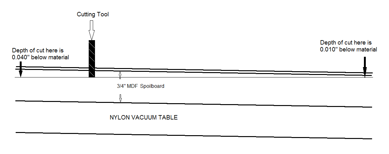
3. MotionMonster Spoilboard Re-facing -  I finally got around to cleaning up the spoilboard on the MotionMonster.  This has to be done anytime you mount a new spoilboard on a CNC router.  There are two main reasons for needing to do this: 1) the main X and Y axes are not perfectly parallel to the top of the vacuum table that the spoilboard is installed on; 2) The spoil board is not a uniform thickness.  In the case of the MotionMaster, the main stationary gantry that is the X axis (and has the spindle carriage mounted to it) is pretty large and heavy.  The best that I can tell, the gantry is about 0.030" out of parallel with the vacuum table/spoilboard.  That's not bad, considering the thing weighs in at about 2 tons.  There are several ways to try to physically make the gantry perfectly parallel to the table.  But, for this small amount the easiest way is to just shave off the difference.  Here's a picture to show what's involved (angles are exaggerated and amplified for clarity):
As you can see in the pic above, if the surface of the spoilboard is not perpendicular and planar to the spindle/tooling, then in order to make sure that the cutter clears the bottom of the material on one side, you have to cut even deeper on the "high" side.  So, the solution is to cut the entire sheet down to be even all over the face of the spoilboard.  Then, when you lay a sheet of material down to cut, the cutter will cut below the bottom of the material by the same amout all over the spoilboard.  Here's a pic of the facing operation.  It looks like a lot of material being removed, but in reality it is less than 1/16th of an inch.  I used a 1-1/2" mortise end mill with a 1/2" step-over to cut the face of my spoilboard down.  It was a little dusty, but it worked well, overall.

4. Main Spar Center Section -  When edge milling the parts of the spar made from the thicker sheets of .100" and .160" (described in the last post), you find out that it doesn't take long before you can get a razor edge on the corners of all the milled pieces.  This is particularly bad in two respects: 1) you can get some really nasty cuts; and 2) it is a property of most metals to form stress cracks (from fatigue failure) at the thinnest point in the material.  These stress cracks, once started, will propagate thru the material if left unchecked.  So, to prevent this from happening, you simply file the edges with a single cut mill file so that the edge has a small radius.  Now, you take these fatigue stresses and spread them out over a bigger surface area and the cracks are less likely to start.
Well, doing this to exactly 18 edges on 19 pieces might be simple, but it is also tiedious.  So, over the past couple of weeks I would do one or two pieces a day, while the router machine was running and it helped to spread-out the "tediousness" (is that a word?).   Anyway, now all of the thick center spar pieces are done and waiting to be hit with the scotchbrite and then the alodine.  Here is the "stack."


 5. Center Section Skin Flanges -   With the spoilboard faced off and armed with a couple of new 1/8" router bits, I decided to give another try at cutting parts.  I was a little "gun shy" of going at this again, with the number of broken bits in my router parts box far outnumbering the ones that are still in tact.  But, I "manned-up" and turned on the machine.  I started using a new style of bit for the first time.  This time a used a 2 flute, straight flute, 1/8" carbide cutter.  The straight flutes are very good for this profile type cutting application because it puts all the cutting forces directly parallel to the centerline of the material and does not try to lift the material off of the vacuum table/spoilboard (like a helical cutter does).  It works much better.  This time I also started with a lot higher spindle speed and a lot lower feedrate. I started with 12K rpm on the spindle and feedrate at 4ipm.  I could tell that I was making aluminum powder for chips so I slowly, step-by-step kept moving the feedrate up and by the time I was done I was cutting at 14K rpm and 10ipm.   I managed to cut out the 10 pieces of the center section spar skin flanges without breaking a bit.  So far, so good - I still have the same cutter in one piece!  Here's a couple of pics:

These are the lower skin flanges for the center section spar being cut. 

 It turns out that at 14K rmp, I should actually be able to feed that cutter at up to 18 ipm.  So, on my next attempt, I'll step the feedrate up a little more.  Overall, I'm very happy with the results.  The parts come out with a burr on the edges (as expected), but they are accurate.  I can match skin flange rivet holes to the holes in the spar caps - and they match, perfectly!  This CNC stuff really works.  It's encouraging.  I am imagining the possibilities to be able to do "matched hole drilling" for most of the parts of the airplane.  The time savings for future kits (builders) would be huge - as compared to previous methods.  Rest assured, I will be working this into the prodcution process whenever and where-ever possible.

 6. Chuck's Having a Blast - Just one quick builder update this time.  I have it from a reliable source that Chuck has been flying his Prowler quite a bit lately.  He is apparently "having a blast" flying his plane.  Rumor has it that the airplane has been operated fairly close to the speed limit, fairly close to the (minimum) altitude limit, and in VERY close proximity to his own house!  Huh - imagine that.  Congratulations Chuck.

That's about all the news that worth using up electrons to post about.  I expect with the work sked coming up and the folks visiting in late Mar, I'll probably try to post an update in early Mar and then again in early April.

As always, thanks for stopping by to check on the progress here at Prowler Aviation.

Sunday, January 29, 2012

A Little More To Report

The day-job has been really slack the past 3 weeks since the holidays are over.  This has provided me with a lot more days in shop.  And, these (otherwise) wasted weekends where I sit around in LA waiting for the phone to ring have provided ample time to keep the blog up-to-date.  Unfortunately, the crazy days of summer (when everyone is constantly calling in sick) are just around the corner.  But, I'll make the best of this while I can.

So, here's what's up lately:
1.  Chromate Conversion of Spar Parts.
2.  Main Spar Center Section.
3.  Press Brake.
4. The CNC Router Vacuum Table.
5.  Chicken Run.

1. Chromate Conversion of Spar Parts - In preparation for corrosion treating the wing spar parts, I've located and purchased a 10lbs pail of Iridte 14-2.  I found it in the LA area at a place called Gallade Chemical.  I paid $26/lbs for the dry power which will make up to 5 gallons of the solution (per pound of dry powder).  Aircraft supply places are charging up to $35 per gallon.  So, buying dry and mixing my own solution is definitely a substantial cost savings.
The problem is, now I have to get this stuff back to the shop in NorCal.  I thought that I'd be able to FedEx it, since they do accept HazMat for shipment.  Unfortunately, they only accept HazMat items from DG certified shippers (Dangerous Goods) .  So, now I  have 2 options: 1. Find a certified DG shipper that will accept this stuff and ship it for me, and ;  2. Drive it home myself between 2 of my reserve stints down here in LA.  I need to call and get a few quotes to see what the shipping option will add to the cost of the material .vs. buying gas to drive it home.  We'll see.
After my last post on this subject, Cabi suggested simple wooden pans lined with poly film.  After checking into it, we decided that this is probably the most cost effective, simple solution.  I will, no doubt, be building these boxes in an upcoming blog update.

2. Main Spar Center Section - I've been working diligently to get the center section of the main spar ready to chromate and assemble.  Here's the progress.  I started by temporarily assembling the spar parts using pins (roofing nails - hey it works!) in enough of the rivet holes to ensure the parts were lined up in the same way that they will be when permanently assembled.
Machining the bearing blocks is the next step, so I had to measure the room available between the bottom of the top set of cap strips and the top of the bottom set of cap strips.  Well, this varied depending on which cap strip happened to be sticking out the most (from the rest).  This made it obvious that I'd have to machine down all the cap strips (assembled as a single unit - minus the shear web).  So, after taking the "stack" back apart, then re-assembling only the bottom strips into a stack and putting it into the mill - here's what it looks like (sorry, the pic is a little over exposed):
The object here is to even out the edges of the cap strips to a uniform dimension so that the bearing blocks can be machined to go between them.  This unevenness is a result of the "manual" process used to fabricate these parts before I got up on the CNC production processes.  When I make these using the CNC processes, this will not be a problem (for future kits).  Here's a shot that shows the before and after of this step:
With this step completed for both the top and bottom sets of cap strips, now a definite measurement could be made of the space between the top and bottom sets of caps strips.  Then the machining of the bearing blocks could begin (knowing this new dimension).  Here's the raw stock being prepped, cleaned up, squared:
Here's a shot of one (of 4) bearing blocks getting the initial hole bored. 
This was pretty close to the limit of use of a hole saw, but it worked and the finish didn't matter since the hole will be cleaned up in the next step.
This rough hole is then opened as needed with a boring bar:
Here is the first test fit of the bearing blocks onto the area of the spar between the caps.  Of course, it's close, but doesn't quite fit.  A little more machining on the bearing block edges fixed that.
When I got the thin portion of these bearing blocks down to 1/16" I stopped taking material off of the bearing blocks and went back to removing material from the appropriate sides of the cap strips (more milling).  Eventually, I got the bearing blocks to all fit nicely on both sides of the spar web.  Here's a shot:
And some close ups:

Notice the bearing blocks are sticking out farther that the cap strips.  These need to be flush to the cap strips (plus 0.040" for the skin flanges that I'd forgotten about up til now - yay).  So, now I just need to face mill the bearing block to the correct thickness, like this:
Here's the completed bearing blocks (minus face milling) with the bearings installed.  Here you can see that the forces of the main landing gear torque tubes are transferred to the bearing blocks, which in turn transfer these loads to the spar cap strips and web, and eventually into the entire wing (which is what you want to have happen):
The one remaining step is to drill and tap a hole in the forward bearing blocks to insert a grease fitting for periodic maintenance (some day).
Once the bearing blocks were installed, I had to re-assemble the "stack" and clean up the edges of the cap strips on the top and bottom of the spar.  Here's the whole stack set up for doing this.  I decided to do this by hand rather than try to get this whole (100 lbs) stack into the mill:
The file you see sitting on the top of the spar stack is a babbit file.  George told me about these files and they do a great job of cleaning up the edges of thick AL pieces.  They are actually made for filing large journal bearings made of babbit, but work great for this too.  Here you can see a before and after of what the edges of the spar stack looked like.  In the before pic you can see the router marks on several of the edges.  On the after shot you can see the router marks removed and a nice smooth edge in it's place:

With all of this done, here is the spar stack completed with the bearings and bearing blocks installed:
Now, I still have to cut out the skin flanges for the main spar center section.  This actually consists of 10 pieces (3 on each top edge and 2 on each bottom edge).  I will have an update on fabricating these in a future post.  I also have to clean up the faces of each of the spar parts with a scotchbrite rol-lok disc.  These work great to clean the junk off of the aluminum.  I started to do this  (you can see the top cap strip above is more shiny than the bottom one and the shear web).  But, I didn't continue to do this to all the parts now, since the metal would start to oxidize again before I get to the chromating.  I decided that it would be wiser to do this just before the chromate conversion process, since this will make the etching step go more quickly.

3. Press Brake - In the last post, I showed how I installed the hydraulics to make the press brake operational.  Well, with the hydraulics worked out it was time to start trying to "calibrate" this machine and figure out a process to get consistent bends out of it.  I started by fabricating a "stop" system to stop the lower die beam at a pre-determined point.  What I came up with was a 1/2" thick piece of flat steel that was 4" long and 2" wide for a top stop.  This piece was bolted to the side frames and is mounted up to the upper die beam.  On the bottom I used a 1" thick piece of steel to use sit on the lower die beam.  Using these pieces in this configuration will provide for the use of calibrated "stop blocks" that do not have to be large and/or tall.  Here's a pic:
 The area between these stop pieces is where the calibrated "stop block" will be placed.  Then, when the hydraulics is activated, the lower die beam will move up until it hits the stops.  There will have to be a different stop block made for each angle of bend that is desired.  Also, the LH stop blocks are not the exact same thickness that are required on the RH side.  So, I'll end up having a set of 90 degree stop blocks, a set of 85degree stop blocks, etc.
In order to try to determine what the "ballpark" value will be for each angle of bend, I next cut up several 1-1/2" x 2" pieces of 2024-T3 (0.040").  I used these pieces to do test bends to collect empirical data to use to plot on a graph.  Using different thicknesses of stop blocks I bent test pieces for each and then measured the resulting angle of bend.  Here's the pieces that I used to obtain this data:
Then, I plotted this data to get this:
As you can see, this is a pretty linear relationship between bend angle in degrees along the X axis and the associated stop block thickness along the Y axis.  The red data and line is for the RH stop block and the blue is for the LH stop block.  The difference in thickness (for the RH and LH blocks) is the result of the stopping system on the LH and RH not having the exact same gap between the upper stop and lower stops.  So, overall this data made sense and seemed to give some positive results.  But, when I tried to machine a stop block of a given thickness and then get the bend angle that is indicated in the graph, the results were not consistent.  I could use the same set of stop blocks and bend three pieces and get three different bend angles.  There seems to be too much variability in the process to give predictable results.
After pondering this for a long while, I've come to the conclusion that the biggest variable factor is the pressure being developed in the hydraulics.  I do not yet have a pressure gauge installed.  Without a gauge, I am likely stopping the bending process on any given piece at a different pressure than the next.  This difference in pressure is probably responsible for adding much of the variability to the data (bends).  Another factor in play here is that the difference in pressures is most likely causing more or less flexing of the dies (more pressure means more die flex) and this is giving the different bend angles for a given set of stop blocks.
I have an idea for a bending process that may take a lot of the unpredictability out of the process and give consistent results.  I just need to come up with a process that gives predictable results before I start tying to bend $100 parts and have them come out messed up and unusable.  I'm going to be trying this (more testing) in the upcoming week and I'll have an update in a the next blog post. 

4. The CNC Router Vacuum Table - Before I can cut the 10 needed skin flanges for the center section of the main spar, I need to face cut the vacuum table spoil board.  I've measured it, and there is about 0.035" difference between the "high" corner and the "low" corner on the spoil board.  Now that I've got an acceptable cutter to machine off the "unevenness" of the vacuum table, I have to write a G-code program to get this job done.  Here is a pic that shows a section view of how my spoil board is mounted to the vacuum table:
The process of face cutting the top of the spoil board is needed because if the top of the spoil board is not perfectly perpendicular and planar to the spindle, it is more difficult to cut an even distance through a sheet of aluminum laying on top of the spoil board.  When you are trying to profile cut parts, you want the end of the cutter to stick out about 0.010" below the bottom of the sheet that you are cutting out of.  This eventually "spoils" the board (hence the name) and you have to re-face the spoilboard.  So, you can consume most of a sheet of MDF in this process before you need to completely replace it.  I am going to try to accomplish this first face cut in the upcoming week as well.  I'll have an update in the next post.

5. Chicken Run - The kids have inherited a few more chickens recently, and suddenly the chicken coop is not large enough. With 3 girls batting eyelashes and asking for help, what's a dad to do? A new, larger chicken run to attach to the existing coop. So, here is where a few man-hours went recently.
Lucky chickens!

Well, that's all that's happened in the shop over the past two weeks.  I should be getting 2-3 more good slack weeks from the day-job - maybe even a month yet.  I'll be in the shop trying to get this wing spar ready to mount in the jig.  That's the main goal for now and I'll be keeping the focus on this for the time being.  Thanks for stopping by to check on the progress.  I'll plan on another update in two weeks.