Since the last update I have finally gotten some parts cut out with the CNC router using the same process that I will use in production some day. I coaxed the MotionMonster to cut out a set of outboard wing spar shear web channels and a do-over of one of the outboard spar cap strips. So, now I have all of the 2024-T3 aluminum parts cut out for the entire wing spar (from wing-tip to wing-tip). After that I have completed the build work on the 8 foot press brake and did one quick test bend.
Here are the topics for this update:
1. Production Parts with the MotionMonster.
1.A. Outboard Wing Spar Channels.
1.B. Outboard Wing Spar Cap Strip.
1.C. Need To Face Cut The Vacuum Table.
1.D. Recap of The Entire Process.
2. Finished Building the 8 Foot Press Brake.
2.A. Building The Back Gauge.
2.B. Building The Beam Deflection Meter.
2.C. Converting a 20 Ton Bottle Jack Into a Basic 20 Ton Ram.
2.D. Assembling The Hydraulics.
3. Researching How To Alodine Aluminum.
3.A. The Chromate Conversion Process.
3.B. Finding The Chemicals.
3.C. Need A Pan
4. Next Update
First up is the new parts made with the Prowler MotionMaster (PMM).
1. Production Parts with the MotionMonster - I'm really focusing on trying to get the wing spar mounted into the wing jig by this March. Before I can do that, I have to have the spar assembled. Of course, in order to do that I have to have all the parts collected. In the last update I posted about making the fixtures and finishing the spar cap strips, etc. Well, after that I got the time to make the remaining parts that I was missing. Namely, the outboard wing spar channels and one cap strip that needed to be replaced.
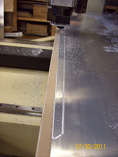
1.A. Outboard Wing Spar Channels - Here is a pic of the machine cutting one of the two spar channels that I need to make. The machine worked great.
Here's a video of the same part being profile cut:
1.B. Outboard Wing Spar Cap Strip - I had to replace one of the cap strips that is the closest to the spar web on the forward side of the spar. The one that I had cut previously came off the edge of a new sheet. Not knowing at the time, I just used the edge of the sheet as one edge of the cap strip. Well, that doesn't work well. Turns out that there are internal stresses that are built up in the material on the very edge of factory sheet. If you cut a thin strip off that edge, it will come out all warped and twisted because the factory edge has stresses and the newly cut edge releases those stresses. Anyway, I didn't like that piece, so I cut a new one. Here's a pic of the profile cut on the outboard end:
And, a profile cut of the inboard end:
1.C. Need To Face Cut The Vacuum Table - one problem that I encountered while making these parts was the fact that the vacuum table spoil board was not perfectly parallel and planar to the gantry of the router. So, one side (and corner) of the table was lower than the other. Well, if you are trying to maintain a constant depth of cut in a part, it doesn't work real well to have an uneven spoil board. The solution is to face cut the spoil board with the router over it's entire surface. Then there will be an exact equal distance from the router to the table everywhere on the spoil board. To do this I needed a cutter that would accomplish this. Looking on the forums at CNCzone and Practical Machinist - I found that guys use a variety of tooling to do this, but a simple 1-1/2" end mill with 2 flutes will work fine.
It just so happened that when I picked up the machine I also got a free slab of nylon with a collection of several end mills stuck into. They looked pretty ratty but I decided to clean them up to see what I'd gotten. Turns out that there was a pretty decent 1-3/8" mortise mill in the bunch - but just needed sharpening. I found a local gent that does AWESOME tool and cutter grinding. He fixed up about 6 of these end mills for me and now I can face off the table. I'll cover that in a future post.
1.D. Recap of The Entire Process - For those not familiar with CNC production process, I thought I'd recap the entire process to give some perspective. There are a lot of parts to the puzzle and this will help give an insight as to the work that's been involved to get to this point in the Prowler production process. So, this is the way that I've done things. If anyone has any ideas to streamline any of this - please share.
1. First I had to create the CAD drawings. I've made many posts about this. In the CNC world, this is where it all begins. To make my CAD drawings I bought and learned how to use a CAD software. Then, I reverse engineered all of the Prowler parts, using a variety of techniques, that resulted in a CAD drawing. For the spar cap strip mentioned above, the CAD drawing looked like this:
2. Next, this CAD drawing has to be stripped down to only lines, points a circles. This is so that it can be correctly converted into a .dxf (a sort-of CAD drawing standard). When I'm done with that, it looks more like this:
3. Then, I take this drawing file and I feed it into a software called SheetCAM. The CAM process takes the drawing and converts into tool paths (paths for a tool to follow). In SheetCAM the same part looks like this with all of the holes and profile cuts programmed.
Here's a more close up of one end to show a little more detail. The S's depict start points for SheetCAM. In this case, each point on the DXF drawing becomes a start point for one drill operation. That's why there are so many S points on this SheetCAM part.
4. When everything is set-up correctly, you tell the CAM software to do something referred to as "Posting." Posting is where the toolpaths are created for your specific machine using something known as a "Post Processor." When the post is done, the CAM software has basically created a text file with a bunch of numerically ordered commands. These commands are called G-code. G-code is a very low-level, simple code that tells the machine how to move in X,Y and Z coordinates, when to turn on & off parts of the machine like the spindle, coolant, etc. This is what it looks like:
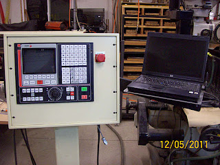
5. Now I go to the laptop that I have essentially hardwired to the CNC router controller. I have to transfer this G-code file to that laptop. Then, I use a software created by Fagor (the company that makes the machine's controller) that is called WinDNC. Using WinDNC I can transfer the G-code program into the controller's memory. If the program is too large, WinDNC has an "infinite" transfer routine that will allow the program to be fed to the controller on the fly, while it's cutting parts. In the industry this is referred to as "drip feeding" the controller. This will definitely get used, since this 14 year old controller has a WHOPPING 32Kb of memory! Yes, that's kilobytes with a K! So far, the biggest file I have cut was the center wing spar web (holes and profile cut) that had a G-code file that was about 13Kb. Here's a pic of the laptop and the controller:
6. With the part program in the controller's memory, I can call the program up and get ready to execute the program. But first, you have to run a warm-up cycle on the machine (before the first run of the day), then you have to load the material onto the vacuum table. Next, I test run the part program with the router set to a "slow" mode that executes one step at at time and with a work offset that keeps the router 1" above the material all the time. During the test run, the sheet of material can be positioned properly, and all the steps can be confirmed to make sure that something funky isn't going to happen. This helps prevent ruined parts, broken end mills, etc.
7. If everything looks right, you can hit the "cycle-start" button (big green button in the lower right corner of the controller above) and start to cut the part. If all goes well, it should look like this when its running:
8. Now, this has to be done for each part (or group of parts) of the plane. However, once I get closer to production, I will be able to group parts that use the same thickness of sheet aluminum together and cut them out in one big program. The ideal idea here would be to have all the, say, 0.040" parts of the airplane gathered together on 4 or 5 sheets of material - for example. Then, to cut out one plane's worth of 0.040" parts, you'd have to run 4 or 5 programs that would make the majority of those parts. At least, that is the ideal scenario - the reality may turn out to be something different. Time will tell.
Well, that's my experience of CNC production so far. As the learning curve flattens out, things will go more quickly. I hope this helps give you a better idea of what is going on here. The real value of this process is that parts on future Prowlers will be interchangeable. Anyone that has seen more than one of these current airplanes will tell you that this is not possible with the previous Prowler kits.
In the previous post I showed how I cut a ba-zillion rivet holes in about 50 spar parts. When stacking them all up on the bench together, THEY ALL MATCH!!! See this:
I can now do the so-called "matched drilling" of Prowler parts that is accurate to one-half of one thousandth of an inch ( That's = 0.0005"). To use a Bryan Davies quote - "THAT'S WAY COOL!"
2. Finished Building the 8 Foot Press Brake.
2.A. Building The Back Gauge - In order to have a semi-accurate method to control the width of the flanges that are bent with the press brake, I needed a back-gauge to allow the material to bump up against before pressing. I started by making some J-hook devices to grab the side of the U channels that support the back-gauge.
Then I welded nuts onto the J-hooks and made up bolts that go thru the back-gauge into the nuts on the J-hooks. I machined slotted holes into each of the back-gauge for these bolts to go through. This works well to set the end of the back-gauge and then tighten it down with the bolt to hold it in position.
I took the U channels and slotted the tops to a depth of 0.025" to allow the metal scale to be set down into the slot.
Here you see the scale, the slotted holes and the hold down bolt. This will be used to set the distance for the back-gauge to the size of the flange desired and then clamp the back-gauge in position.
Here's what the whole system looks like installed on the back of the press brake.
Next up was installing the "deflecto-meter".
2.B. Building The Beam Deflection Meter - In order to accurately control the plunge depth when bending metal, it's best to have a ram located at each end of the beam that has the lower die attached to it. In this configuration, however, the beam will deflect (down) in the middle (due to the resistance of the piece that you're bending) when the rams are lifting on each end.
Here is a bracket that I welded onto the center of the sliding beam and then attached a dial indicator. Below the dial indicator you can see the edge of a 3/16" by 4" flat bar that is mounted to the face of the sliding beam. This flat bar is only mounted to the sliding beam at the ends of the beam. This way, when the beam deflects up on the ends (and down in the center) - this flat bar moves up with the ends of the beam. This movement will be displayed on the dial indicator (see 2 pics below).
Here you can see the press brake with the bar installed on edge onto the face of the sliding beam and bolted at each end. You can also see the dial indicator mounted in the center.
Here is the dial indicator mounted with the "shelf" in position pushing up on the indicator probe when the beam deflects.
This will be used with (eventually) a third jack. This center jack will be used to jack out the deflection when pressing a flange into a piece of metal. Jacking the outer jacks will do most of the work bending of the flange and cause the beam deflection, then the center jack will just take out this deflection to ensure a straight and accurate bend. During test bends, I was seeing deflections of 15-25 thousandths. In terms of angle of bend, that's about 2-4 degrees of bend. I've calculated that on a 90 degree flange bend, each 0.006" (approx) of plunge depth corresponds to about one degree of bend angle.
2.C. Converting a 20 Ton Bottle Jack Into a Basic 20 Ton Ram - This is a little off topic, but I thought that I would include this section in case anyone ever wants to convert a cheapo bottle jack into a hydraulic ram. Someone googling "convert bottle jack to hydraulic ram" might find this info helpful. The idea here is that a bottle jack has a lever operated pump that pumps hydraulic oil (up to 10,000 psi) under a piston to produce (forceful) linear motion. By machining an auxiliary port into the area under the piston you can use a separate source of hydraulic power to lift the piston (and ram). So, here's how I did it.
1. Pull the reservoir plug and drain the hydraulic oil out of the jack.
2. Now, remove the bleeder valve and drain any residual oil from it. You might have to tip the jack around a bit to let the air into the bleeder valve cavity so the oil can drain out. If you don't do this now, it's OK - but the oil will eventually come out. It'll just come out where you might not want it to - when you least expect it to.
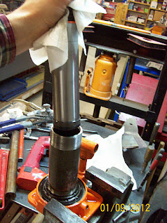
3. Hold the base of the bottle jack in something that is rigid and strong. I used a large vise, but I had to make sure not to "pinch" parts of the jack that you don't want pinched. The inside jaws of the vise have ahold of one end of the flat part of the base of the jack.
4. Remove the big retaining collar at the top of the jack. This is really nothing more than a big hex nut that squeezes down on the reservoir outer jacket and seals it between a large flat rubber washer on the bottom and the top to form the outside of the reservoir. These parts will be on tight and will require large tools, lots of uumphf, and sometimes a 3 foot cheater bar to get them to loosen up.
5. Now remove the reservoir outer jacket. You can see the flat rubber seal on the top in the pic above and in the pic below you can see the rubber ring that seals the reservoir on the bottom.
6. Next, you'll need a big pipe wrench to remove the hydraulic cylinder. This is just a piece of high strength steel pipe with threads on each end. It's the cylinder that the actual piston and ram travel in when moving up and down.
7. Once you have the base of the cylinder loosened you can remove the piston and ram. I waited until I had the base loose before removing the ram so that I didn't get any junk inside the cylinder. But, with the bleeder valve removed, you can pull the ram out at any time.
Notice that the piston is just a little bigger than the ram on the bottom. That's the part that hits the big nut on the top to prevent it from flying out of the cylinder when it reaches the top of the cylinder. It also "counts" in the surface area when calculating the force of the jack.
WARNING! - MATH SIDE-BAR - FOLLOW AT YOUR OWN RISK!
The force of the jack is equal to the fluid pressure times the surface area of the piston (F=P*A).
Area of a circle is pi times radius squared or A=pi*(R*R).
Also, radius R is 1/2 the diameter (R=D/2).
Bottle jacks (I've come to find out) are designed to develop 10,000 psi.
After all the substitutions, then the force of the jack can
be expressed as F=P*pi*(1/4)*D*D.
Now, solving this equation for D
gives us the following: D=square root [(F*4)/(P*pi)].
In the case of this 20 ton bottle jack
D=square root [(40,000lbs*4)/(10,000psi*3.1416)].
A quick calculator operation gives D as 2.25 inches.
My ram is 2" and the piston adds the .25 inches.
Hey, math works! At least that's what I'm trying to convince my kids of these days.
Back to the conversion.
8. Remove the cylinder, the rubber seal rings and clean up all the oil. Remove the lever pump inlet screen (first pic below). Then remove the little plastic corner mold piece in the bottom (second pic below). I'm not sure what this even is!?!?! But, I didn't want to get machining chips stuck under it, so I took it out for next few steps.
9. Mount the base of the jack in a mill, mill-drill, or even an adequate drill press. Here's mine:
10. Find a suitable place to machine in a hole for the aux port. Used a 1/4" NPT male to 3/8" NPT female adapter to connect hoses to my rams. I chose this because when you go looking for 10,00 psi hose, they all come with 3/8" male fittings on the ends. So, the next size down seemed appropriate for the aux port. For a 1/4" NPT femal hole you'll use a 9/16" hole with a 1/4"-18tpi pipe tap. I used a 9/16" end mill, but a regular twist drill bit would work. I'm sure that different jack manufacturers will have different base configurations. In my case, I used HFT 20 ton bottle jacks and they have this nifty little flat spot cast into the side of the base opposite the lever pump. Imagine that! I wonder if that might have been for, say, an auxiliary port!! No - you don't say!
11. Make the hole. Try to position the holes you make to keep as much material surrounding the holes as is possible. This will help the base maintain it's strength with 10,000 psi trying to rip it apart when you are using it. On the 10,000 psi hydraulic fittings I used I measured a wall thickness of around 3/16". So, for steel, I tried to maintain that wall thickness everywhere I could in the base of the jack. I machined my big 9/16" hole to a depth of 3/4". This should be enough to get the tap all the way in as far as needed.
12. I then drilled a 1/4" port from the bottom of this hole deeper into the jack base until it is under the piston area. The hole is offset from the big hole since I was trying to shoot for the middle of the material in the base of the jack.
13. Then I tapped the big hole while the base was conveniently held on the mill. I learned a neat trick from a friend for starting taps straight. Use a large flat surface (like an upside down 3/4 end mill) in the spindle to push down on the top of the tap. Then keep pressure down onto the tap with the spindle handle while you turn the tap. A little oil on the top of the tap helps. This will keep the tap straight up and down while you get the first several threads cut. Then you can lift the spindle out of the way and continue to tap the hole. Worked good.
14. Continue to test the fitting into the new threads. Ideally, you are looking for 2/3 of the threads on the fitting to screw into the hole. If you're not getting that, take the fitting back out and cut a few more turns with the tap. I found out that cutting pipe tap threads is very different than cutting bolt hole threads! Especially if you don't taper the hole - which I did not. My tap (with several missing thread lands now) shows the error of my ways. But the tap was only $5 and it got the job done.
15. Now I turned the base flat and machined in a short hole down from the top of the area under the piston to meet the 1/4" hole that I previously drilled. This will complete the port into the area under the piston. Make sure it lines up!
16. Ta-Da! An auxiliary port is now installed in the 20 ton bottle jack. Well, not quite. We still have to put it back together. Here you can see the new port (it's the one at the bottom of the picture). The port that is on the top (inside of the threaded shoulder that the cylinder threads into) is where the hydraulic oil comes out of the lever operated pump. The little plastic do-hicky holds the check valve ball in place and keeps it from unseating if you tip the jack upside- down. As you stop each stroke while hand pumping the jack, the pressure inside of the cylinder pushes down and seats the ball tightly - preventing the loss of pressure inside the cylinder until the next pump stroke. When using an auxiliary port (and pump) this ball valve just stays seated and no pressure gets back to the lever pump. The lever pump gets is oil from the reservoir which is the hole at the very top of the pic. The reservoir is the area between the threaded collar and the outside jacket of the bottle jack.
The hole on the right (inside of the threaded collar) is where the hydraulic fluid leaves the area under the piston when you crack the bleeder valve to lower the jack. This oil then comes up into the reservoir thru the hole at the very right (again between the threaded collar and the outside jacket). Oh, you can't see it in my pictures, but I put plugs in all these holes before I started cutting any metal to prevent chips from getting where the don't belong.
17. Now do steps 1 thru 8 in reverse to put the jack back together. Don't forget to very carefully clean ALL of the little chips and metal shavings out of the entire jack. You can re-use the hydraulic oil, but I filtered mine thru a paper towel first to get rid of any metal shavings, paint chips, etc. When screwing the cylinder back it, put all your might into it. If it's as tight as you can possibly get it, then it's probably tight enough. The big nut needs to be tight, but not hugely tight. It doesn't seal anything, all it does it hold the outer jacket in place (between the rubber seals) and acts as a stop for the piston travel. So, make it good and tight, but don't cut thru the rubber seals.
I did this with two jacks for the press brake project. Here's what they looked like when I got finished:
The real beauty of doing this with a bottle jack is this. If you find that you don't want to use it as just a ram with an aux pump any longer, you just put a 1/4" pipe plug into the hole - instead of the 1/4" fitting you see here. The jack is then back to being just a bottle jack and operating just as it did before the conversion. Sweet!
2.D. Assembling The Hydraulics - With the bottle jacks converted to rams, it was time to start putting it all together. Next there was a trip to the hydraulics store to buy the hoses, fittings, and more fluid. Then a trip to HFT to get this air-over-hydraulics pump.
I chose this pump since it is fairly inexpensive and I wanted to try to keep the cost down until I knew for sure that this thing was going to work. As it turns out, it works pretty well. So, the first step was to put the fittings into the jacks, then connect the hoses to those fittings. Next I had to machine a junction block to split the hydraulic fluid flow from the one pump into two lines (one for each jack). Here are a few pics
Once this was done I connected the line to the air-over-hydraulic pump and then bled the air out of the pump. Then I installed it into the press brake and it now looks like this:
The junction block is on the back side of the lower beams. Pressing the foot pedal moves the lower beam up plunging the upper die down into the lower die. The metal gets bent in a process called "air gap bending" and is depicted by this drawing:
I did one test bend with a 7 foot ratty old piece of sheet steel that I had laying around the shop. The press brake worked really well - the hydraulics worked great, the deflection measuring system worked very well, the back-gauge works great, and most importantly the bend came out nice and straight. I have more tweaks to do to the system, but overall this purpose built machine is working out well and I'm pretty happy with the results.
Now that the hydraulics are working, I'll start to begin the process of calibrating the press brake to determine the exact plunge depth that will give the best bend results for each desired angle of bend. Oh, yeah - and somewhere in there I need to work out time for a paint job on the press brake.
3. Researching How To Alodine Aluminum - In an effort to try to plan ahead, I've been researching the Alodine process. Alodine is essentially a form of chromic acid. The purpose of this process is to aid in preventing corrosion in the aluminum. It is believed that this process will protect the aluminum up to 30% longer than skipping the process and painting bare aluminum. It is used in lieu of an anodizing process, because trying anodize a complete airplane is simply cost prohibitive. Alodine 1201 is actually a brand name of this solution that is made by Henkel (a mega-conglomerate company). There is an alternative to Alodine that is called Iridite 14-2 and it is make by a company named MacDermid Chemical. Dupont also makes this and it is called Dupont 226s.
After reading many google hits about Alodine and Iridite, I've found out that the real deal with doing this is NOT paying Aircraft Spruce $35 per gallon for this solution. If you like, you can check some of them out here, here, here and here. If you can find the dry powder form, you can get a lot more bang for your buck by mixing it yourself (thus saving about $20 for each gallon of water).
Additionally, each manufacturer has a pre-treatment solution that they recommend. Henkel calls their prep solution Alumiprep. MacDermid calls their solution Isoprep 188. Dupont's prep is Dupont 225s. Turns out, this solution is an etching solution that cleans the aluminum very well before treating with the chromic acid. This solution is really just a 1/3 mix of water, 1/3 phosphoric acid (75%) and 1/3 ethylene glycol. The phosphoric acid strips any oxidation off of the aluminum, the glycol acts as a surfactant and the water is the mixing solvent. These chemicals are readily available at any chemical supply place. So, I'll probably mix my own.
3.A. The Chromate Conversion Process - This is actually, the technical name for this process. Essentially you take your aluminum parts, one at at time and soak them for a while in an acid etching bath. Once it is adequately etched, you remove it, rinse it with water and then put it directly into the chromic acid bath. You let it soak in there for a period of time and then remove it and, again, rinse it with water - then let it dry. The exact process is provided by the manufacturer when you purchase the materials. There are also plenty of hits to review if you google Alodine, Iridite, or Dupont 226s.
3.B. Finding The Chemicals - I am having a hard time finding a dry powder form of any of these chromic acid compounds. The only one that I have located is the Iridite 14-2 that I can buy down in the LA area, but I'll have to get it to the shop. Since it is a HazMat item, it's not easy to ship. But, FedEx will probably be able to ship it. I'll have to check. The rest of the materials I'll be able to get locally. I have a chemical company in Sacramento trying to round up all these chems for me. If they can find the powered chromic acid, I'll get everything from them in one order.
3.C. Need A Pan - Trying once again to plan ahead, I think I'm going to have to locate some kind of pan (2 pans actually) to dip these spar parts into during the Alodine process. One pan would be used for the etch solution and the other one used for the chromic acid. Assuming the center wing spar web is the largest of the spar parts, the pan will need to be about 8'6" long, 18" wide and about 2 inches deep. I remember reading somewhere that PVC works well for these. Now to find something to fit that order. I'll keep you posted.
3. Next Update - As I mentioned earlier, calibrating the press brake is next up on the list along with getting the chromate conversion process completed on the spar parts. I will also attempt to face cut the vacuum table spoil board on the CNC router if the opportunity presents itself. Those will be the focus for the next update, hopefully in a month or so.
As always, thanks for stopping by to check up on us.












2 comments:
How are the hydraulics working?
Hi, post an video in youtube working machine.
Post a Comment