Thanks for stopping to see what's going on @ Prowler Aviation. I don't have a lot to report this update, but a few goods things are happening and I am trying to keep my promise to update more often. So, in this update:
1. Ray has started his Prowler
2. Bryan's Build Update
3. Building More Retaining Wall(s)
4. Start on the Low Pressure High Volume Hydraulic Pump
5. Getting Materials & Tools For Tip Ribs
6. Also Looking Ahead To Spar Completion
1. Ray has started his Prowler - Ray started his airplane for the first time on Oct 13th. He reports having to sort through some issues, but the engine is running fairly good. Here is a video he sent me:
The biggest bug of the engine runs is the fussy fuel control. The system seems to be very sensitive to throttle changes and the mixture has to be adjusted constantly for every throttle movement to keep the engine running. Ray has contacted the fuel injection manufacturer and is now working with a representative to get the system set up correctly. The first issue is to add a fuel-flow meter system to the airplane. Apparently, in order to properly map the fuel to air, the system has to have a fairly accurate fuel-flow indication.
After the engine runs, as not unexpected, he found a few small leaks that have been corrected. He also found that the prop was not completely snug down to the prop flange on the reduction gear cause by a slightly over-sized o-ring. So, that will be corrected when the prop gets removed soon for other work that will need to be done.
Congratulations Ray!!! That is a major milestone in your project. You are going to have one awesome (running / flying) aircraft soon!
2. Bryan's Build Update - Just a quick update from Bryan. The hydraulic pump that Bryan and I were having a problem bleeding has been returned to the manufacturer. They are still working on the pump/motor. in the meanwhile, Bryan has installed the roll bar (AKA the windscreen frame). Here's a pic:

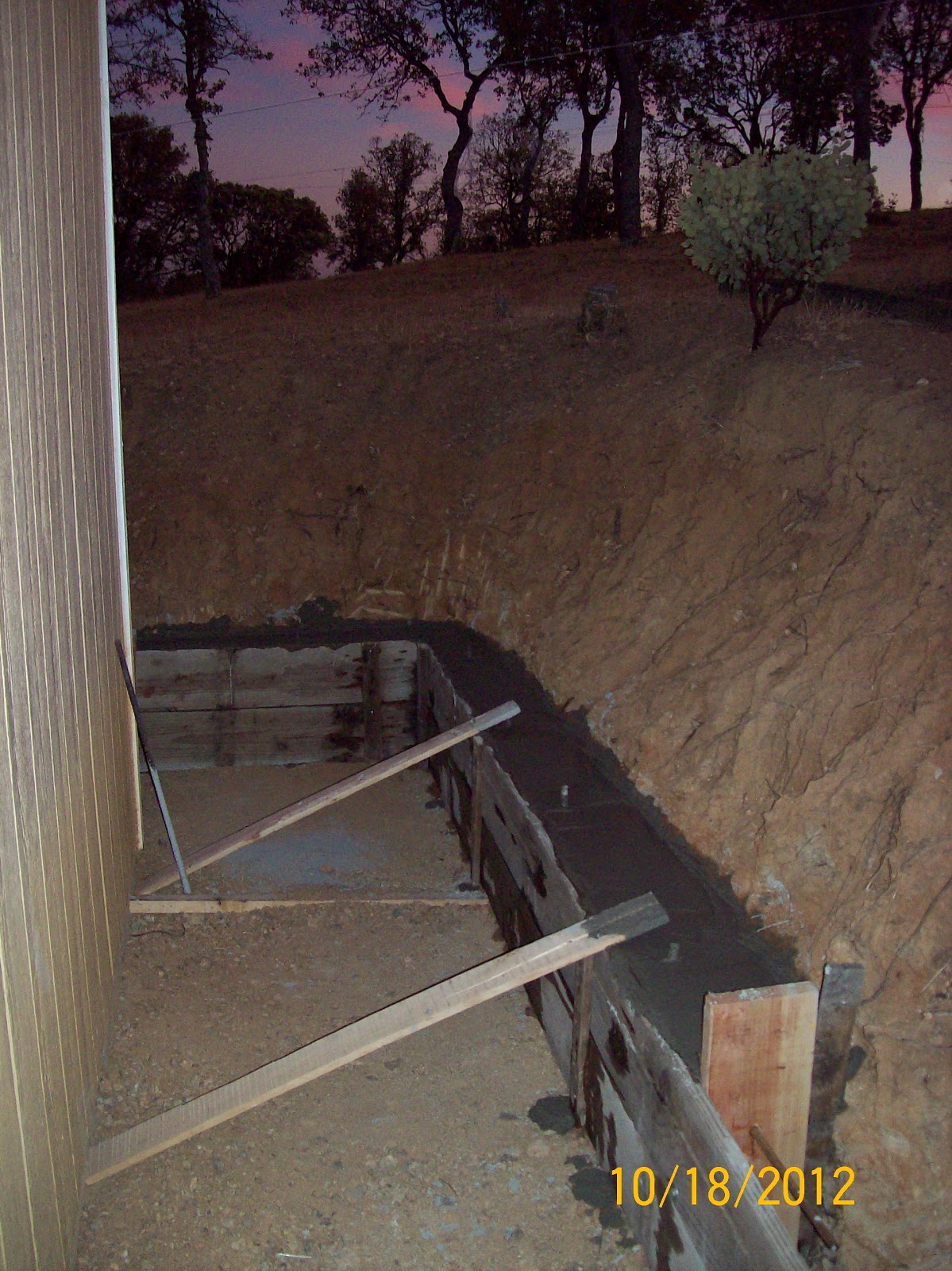
3. Building More Retaining Wall(s) - Since building my shop, I've been ignoring a problem with the steep bank that was cut into the hill where the building pad was cut. Here's a composite pic of what it looked like after the pad was cut and before the slab was poured:


In addition to all of this work, I also got 4 loads of fill dropped off to help expand my shop driveway on the north side of the shop. This fill will settle over the wet winter time and provide a more permanent place to park the RV next summer (and beyond). It will also provide back-fill for the "Great Wall of Prowler" as I continue to work on it (probably next spring). Here's a pic. You can see the partially complete north end of the great wall in the lower right hand corner:


4. Start on the Low Pressure High Volume Hydraulic Pump - I have been taking the opportunity [while NOT working on retaining wall(s)] to look for and buy parts for the hydraulic system I need to assemble for the pseudo-hydro forming press. I was searching for a Low Pressure/High Volume (LP/HV) pump solution to add to the existing system. I looked into electric motor driven systems, but they are usually expensive and designed to run full time. I don't need that for this application. I looked at 12Vdc hydraulic units used on dump trailers, etc. But, they don't come up on eBay or Craigslist often - unless they're worn out or broken. Also, they are not real high volume and new, they want $300-400 for the units. Then, I came across an eBay add for a manual pump made from a Parker hydraulic double acting ram. I liked that this idea was simple, fairly fast, and not too expensive ($50). Here's a picture of the pump as it was in the auction ad:


Here's how I envision the final system will work:
1. Place die, blank, and rubber in the press box.
2. Ensure LP Return Valve is closed.
3. Ensure LP Supply Valve is open.
4. Use manual LP/HV pump until rubber partially smashed.
5. Close the LP Supply valve.
6. Mark position of press box (vertical height).
7. Step on the HP/LV air-over-hydraulics pump and press part.
8. Step on the HP/LV pump pressure release and lower press box.
9. Stop at same place marked in step 6.
10. Open LP Return valve and lower press box to bottom.
11. Remove rubber, part & die.
Here are the the 10,000psi isolation valves I and a short hydraulic hose that I bought so far:

5. Tip Ribs - Getting Materials & Tools Lined Up - I have also been using the time while I'm building retaining walls to gather up some tools and materials for getting the tip ribs made this winter. Here is some of the planning data, in no particular order:
1. I've decided to start making my dies from aluminum (at least for the time being). Every part that will need to be formed from a die will have to be made using this process and will have to have a new die made from AL. I haven't even tried to count them all yet - I'm afraid to.
2. I have all of the CAD drawings of all of the parts to be formed completed already and the profiles can be CAM'ed and sent to the Ganesh CNC mill fairly readily.
3. The flanges on the blank (as they are being formed) cannot hit the bottom of the press box, so the aluminum plate that the die is fabricated from has to be a min of 1" thick. The dies must also be made individually for each part and the same die CANNOT be used for the opposite handed part (in other words, the LH die cannot be used to make the RH parts, and vice-versa.) This is due to two reasons:
3.A. The sides of the dies have to have a rather large radius on the top edge to prevent the blank from cracking during forming, and:
3.B. The sides of the dies have to be undercut by 9-10 degrees to allow for spring back during forming. Here's a pic of what that will look like:
4.A. Cut the die profile (what you see looking from the top down). Here is a sample of the tip rib CAD drawing that I recently re-designed and will use to cut the tip rib dies. The top profile in the pic below will be the one used to fabricate the basic shape of the tip rib die. Looks like I will need aluminum plate that is at least 25" long and 3.5" high:

4.B. Cut the 1/8" to 3/16" radius in the top edge of the die (using the same profile). This can be done using standard off-the-shelf radius end mills.
4.C. Cut the "under cut" to allow the flanges to be "over-bent" to allow for spring-back. Here is the tool that I had specially made by a local tool-and-die maker ($125):


6. Also Looking Ahead To Spar Completion - Once I have the spar installed into the jig, I will have to take it back out to do the corrosion proofing (chromate conversion process - AKA "Alodine"). You may recall from a previous post this early this year that I spent quite a while researching the chromate conversion process [(see it here) Item 3. - almost to the end of the post].
Here are the parts of chromate conversion puzzle (readers digest version):
1. You have to have an etchant to clean the aluminum thoroughly before applying the chromic acid (Alodine, Iridite, etc.). In the link above I learned that this etchant can be made from 1/3 phosphoric acid (75%), 1/3 ethylene glycol, and 1/3 water. This makes a 30% etchant solution that can then be diluted further, as needed, to clean the aluminum parts. So far, I've found and purchased the phosphoric acid from Sierra Chemical Supply in Sacramento:

2. You need to have the chromic acid. Here is the 10lbs pail of Iridite that I got from a chemical supply place in the LA area. I ended up driving it home on a family trip - shipping is complicated because it is a hazmat (oxidizing) substance. This dry powder gets mixed with water and each pound of dry Iridite makes 5-6 gallons of chromic acid for the chromate conversion (AKA "alodining").


4. When you have all this mixed and set-up the process goes like this. Dip a part in the etchant and let it sit until it is dull in appearance and when lifted out of the water the etchant runs clean off and doesn't "stick" anywhere on the part. If it sticks, it goes back into the etchant for a while longer. Once it's clean, the part comes out of the etchant and then gets thoroughly rinsed with water. As, soon as it is rinsed it it placed into the chromic acid tank and soaked until the surface gets a yellowish to brownish appearance. Then the part is removed, rinsed again with water and hanged to dry. Repeat for all the parts. There are lots of YouTube videos to watch on how to do this.
That's all for this update. Thanks for stopping by again to check on the progress here at Prowler Aviation.


No comments:
Post a Comment