Welcome to our 50th blog post! That's a small milestone for Prowler Aviation. So is the topic of this update - getting the Rib Smasher operating. Thanks for stopping by.
I had some time so I figured I'd do a quick update to include the accomplishments of my last trip home. It rained most of the time that I was home, so I had no choice but to get some work done in the shop. So, this update really only addresses the work on the hydraulics system for the "Rib Smasher." (Pseudo Hydro-Forming Press is too wordy and just doesn't describe what it will really be doing!)
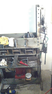
The current progress on the airplane is stalled on making the tip ribs. When I have the tip ribs made, I can finish installing the wing spar into the jig. To get the tip ribs fabricated, I need to have the Rib Smasher press built. The press is mechanically complete, but still needs the hydraulic system installed that I outlined in the last update.
So, that means that the project at hand is to get hydraulics installed on the Rib Smasher. First step is, you gotta have a plan. In the last update I posted a hand drawing of the simplified hydraulics system. Here is a cleaned up version of that drawing that more accurately reflects the system that I designed for the press:
In the previous version, there were two HP manifolds connected by a common hose. I initially thought of that because I had most of the HP system already in tact from a previous application. After further consideration, I decided that if I had to make a 2nd 3-port manifold anyway, I might as well just made a 5-port HP manifold and simplify the system. But, then I also figured out that I could put the return valve "behind" the LP isolation valve and reduce the HP manifold by one port (ended up a 4-port manifold). I'm glad that I did - it makes for a very clean installation.
Here are the parts of the system that I purchased from the local hydraulics shop:
That left me with with two 1/4" manifolds (one 3-port and one 4-port) to fabricate and one 3/8" HP 4-port manifold to make. To make the 1/4" manifolds I found a piece of 3/4" steel plate laying around the shop and cut it into two pieces:
Then, I popped those into the manual mill and cleaned up the edges:
Next, used the DRO on the mill to space the port holes for them:
After that, I took them to the drill press to make the 1/4" holes connect all the ports internally. Then used the 1/4" hole as a pilot for the 7/16" drill to enlarge the hole for tapping to the 1/4"-18tpi female pipe thread (FPT)
Here are the two manifolds with the holes drilled, but not yet tapped:
All that was left to do then was tap the holes. That's not the easiest thing to do. Pipe thread taps are tapered so, the farther the tap goes in, the harder it gets to cut the threads. That is done purposefully, as the tapered hole and the tapered fittings get very snug when put together - which is what you want when you are trying to contain 10,000 psi! Here is one of the two 1/4" manifolds completed:
When the check valves that I bought online showed up in the mail, I could start to piece the system together to get an idea of size and spacing and how to install it all on the press. Here is an initial assembly:
When I initially laid out this system, I had planned on double ended 1/4" MPT ends on the check valves. When I couldn't find all 4 of the same check valves at one place online at a reasonable cost, I switched to the (brass) ones shown in the picture above. However, they have one end FPT and the other end MPT. So, the gaps you see is where I needed 4 double ended MPT couplings to finish the connections. I picked those up at the hydraulics shop the next day.
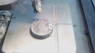
With the LP side of the system taking shape, it was time to switch to the HP side and knock out the 4-port manifold there. To cut 3/8" holes into a manifold, using a piece of 3/4 steel doesn't seem thick enough. So, I decided to use at least a 1" thick piece. All I could find laying around the shop was an 1-1/4" circular cut out (surplus) that I picked up on the cheap at the local steel fab place. So, I cut it up into a 1.25" x 2" x 3.5" block:
Again, cleaned it up on the Bridgeport manual mill and then drilled the ports and tap holes:
Then tapped the 4 holes to 3/8" FPT:
The two small holes you see in the face of the manifold are 1/4" holes that are used to bolt the manifold to the side of the press. The small hole you see in the end above the threaded hole is a goof. That's what you get when you're not paying attention and start to cut the hole before you check to make sure it's on the correct side. Fortunately, I caught it before I bored the hole too deep (only about 1/16" - and it didn't ruin the part.
With this complete, the easy part of the project was over. Now, it was time to start spilling, dripping, slopping and squirting hydraulic oil - everywhere. Try as you may, it is impossible to work on any hydraulic system without getting oil on you, on the floor, on the machine, on your tools, and generally on everything. If you think I'm kidding, just wait until you try your 1st project. If you already have this experience, then you know what I mean!
Anyway, I started with assembling the HP side of the system. I had to take apart the old system and reassemble the HP hoses, the HP manifold, the LP isolation valve, the HP/LV pump and, of course, the 100 ton ram to create the system detailed at the top of this post. Here is a (out of focus) picture of the system installed on the press. It is not a great pic, but you can see the major HP components:
The manifold is mounted on the side of the press at the right. The hose going off the back (right side)of the manifold goes down to the aux port on the far side of the 100 ton ram (red). The brass plug on the aft top port is where the HP pressure gauge will be installed. The LP isolation valve is threaded directly into the forward top port and has the handle facing out toward the operator. And, finally the blue HP/LV pump is threaded into the bottom port on the manifold. The plug was installed so that I could test the HP system before moving on to plumbing the LP side of the system. I eventually got the air out of the HP side of the system and the pump and the HP side finally tested satisfactorily.
Moving on, I began work on the LP side of the hydraulics system. After trying several iterations on and off of the press, I found the combination of plumbing that allowed the reservoir tank, the manifolds and the check valves to all be mounted neatly on the side of the press. Here is another not-so-good pic:
In the above pic you can see the bottom of the reservoir tank (top). The plumbing and valve on the back (right) side is the feed from the reservoir down to the intake check valve manifold. I had initially bought a hose for this connection, but decided to hard plumb this connection with 1/4" pipe fittings to save space. This part of the system does not hold any pressure, so I could just use basic steel pipe and fittings. The Tee's in the middle have a check valve on either side and the unconnected ports eventually got hooked-up to the manual pump. In the foreground you can see the output manifold and the hose that takes the hydraulic fluid down to the LP isolation valve on the bottom side of the manifold. On top of that manifold is the recirc valve and hose that takes the fluid back to the top of the reservoir tank.
This picture shows the connection of the LP side of the system to the HP side of the system via the LP isolation valve:
In order to have room to get back in the corner to install this stuff, I had to remove the manual pump. It attaches with the two bolt holes you see in the side of the press.
Here is a pic of the entire system. You can see the manual pump has been re-installed with the hoses that curl and go up to the Tee connections discussed above. Again, it's not a great pic but you get the idea:
The hardest part of assembling an installed hydraulic system is getting the air out. When the components are hooked to a several hundred pound steel press - "burping" the system can be a little challenging. But, I got a lot of the air out by pre-filling most of the components before assembling them. Then the rest of the air has to be either: A.) cycled out (and into the reservoir) by recirculating the fluid with the pump; or B.) individually loosening each part and then turning, twisting, shaking or otherwise moving it to try to get the air pockets to move to the "high" side and out of the system.
Once I did that, I was able to test the entire system and eventually got the press to hold 1,000 psi with just the manual pump alone! See it on the gauge here:
Later, I got the HP pump to get the HP side of the system up to 2,000 psi without any leaks. Now, I will have to continue to test to higher pressures in steps - eventually working up to full pressure.
So, this is a big step in the progress of Prowler Aviation. If this press is capable of forming wing ribs, fuse formers, etc. (as I hope it will) - this is the last major part of the production process required to someday start making airplane parts for kits.
There still is much to do, including:
1. Finish pressure testing the hydraulics system to ensure it doesn't leak (up to 10,000 psi - if possible).
2. Make sure that the press will mechanically handle the 100 tons of force created by the 10,000 psi.
3. Chop up the several large inner tubes that I've scavenged up over the past year into pieces to be used in the press while making parts.
4. Buy or make a heavy rubber pad to go on top of the inner tube pieces that will help distribute the pressure from the top platen (top of the box) into the inner tube pieces and then into the parts.
5. Start cutting some test dies, test blanks, and forming test pieces to learn how to form these parts (keep the metal from cracking, etc.)
Then, assuming the tests go well, I can start to make the 1st parts - the tip ribs. That will involve cutting a full sized die for both the LH and the RH tip rib. I've discussed this some in a previous post, and I will again when I get to that point. So, stand-by for more on this.
There will be a lots of die making. As I begin to decorate the spar with all of the nose ribs, mid ribs, longitudinal and transverse bulkheads, etc., every formed part of the airplane will have to have an individual die made to use in forming the that particular part. I don't know the exact count, but my best guess is probably about 200.
Retaining Wall Sidebar - There was one day while I was home, that was nice enough to try to get some work done on the wall. I mentioned previously that our dirt in northern CA is like "Marshmallow Fluff" when it is wet. Well, as I was clearing some mud so that I could remove the forms from the recently poured concrete cap pieces, I shot this short video clip:
That's all for this quick update. Thanks for checking in. I will attempt to get one more update done by the end of the year.








No comments:
Post a Comment