I've had a couple months lately where I didn't have much support work to do for any of my current Prowler builders. This has afforded me some time to tackle some of the projects that have been sitting around on my various work benches for far too long. One good example is nose rib dies. It's crazy to think that it's been over 4 years since I cut 4 nose rib dies so that I could replace 4 nose ribs for Francis! Para 1. here: (http://prowleraviation.blogspot.com/2014/12/more-rib-fabrication-and-santa-brought.html)
Since then, I've had 3 more nose rib dies cut out (rough cut with the band saw) sitting on a bench waiting for a chance to put them in the CNC mill and get them done. Well, that time finally came this past couple months! More later.
Also, I spent some "down time" in a hotel recently and used it to set up a Prowler Aviation YouTube channel. You can find several videos of Prowler content here:
https://www.youtube.com/channel/UCvCZN-7jUt6ZKqn_KOFKV-Q
Head on over and check it out. If you're interested, please subscribe.
In this update:
A. Completing 2 Sets of MLG Torque Tubes
B. Making Parts of a Tailwheel Hydraulic Actuator for Ray
C. Hydraulic Repairs to 400 Ton Press
D. "Project X" - Making Test Parts For New Owners of Another
Kit Aircraft Company
E. Finally Completed Dies For All the Outboard Nose Ribs
F. Ray's Work on MLG Torque Tube Pivots
G. An Update From Francis
Before I start with the Prowler update items, I've got a cool feedback type report to share. For those of you that have followed my blog for a while, you may recall that I reported various times about working on and completing the installation of a backup diesel powered electric generator for my property. (Item #4 here: http://prowleraviation.blogspot.com/2016/02/kit-15-has-new-owner-rays-tailwheel_17.html).
In mid Feb this spring, we had a freak snow storm in the Northern CA valley area and we got 6-11 inches of wet, heavy snow (depending on the exact location). At the shop, we got about 6 inches. To the north of us, they got more like 10-11 inches. Check this out:


Now, I grew up in east central WI and snow like this isn't impressive to me. But, for our area of Northern CA, this is not at all normal. Typically, once each winter it snows just enough to make the ground white and it usually melts off the same day. Well, because it never snows this much here AND because it was so wet and heavy, it stuck to all the trees and pulled them down by the 1000's!!! Of course, falling trees play hell with power lines and (you know where this is going), we lost normal PG&E power. In fact, our power at home was out for 8 hours short of a full week!! Thankfully, we had the backup diesel generator, and it proved it's worth in spades!! Here's a picture of it as it currently looks installed in the gen shack:

This one power outage event made all the work, cost and time invested into building and installing this system very, very well worth it! If you live in a rural area and you have the ability to build or buy something similar, it is definitely a worthwhile investment!
A. Completing 2 Sets of MLG Torque Tubes - Another project that had been sitting on the bench for a while was completing a few sets of MLG torque tubes that I started last year. In a previous update, I covered the fabrication of the main portion of the torque tubes. The only thing remaining was to cut a bearing retaining sleeve for each torque tube, drill and tap some holes in the correct locations and install some temporary screws to hold them in place for shipping, etc.
To start this part of the project, I had to put each torque tube in a super spacer mounted in the mill. Then, the flat part of the end flange had to be aligned 90 degrees to the mill table like this:


With the mill centered on the long axis of the tube and the set to X=0 at the aft edge of the stationary sleeve, I cranked the X axis to get the correct hole position for the removable sleeve and marked the hole with a center drill:


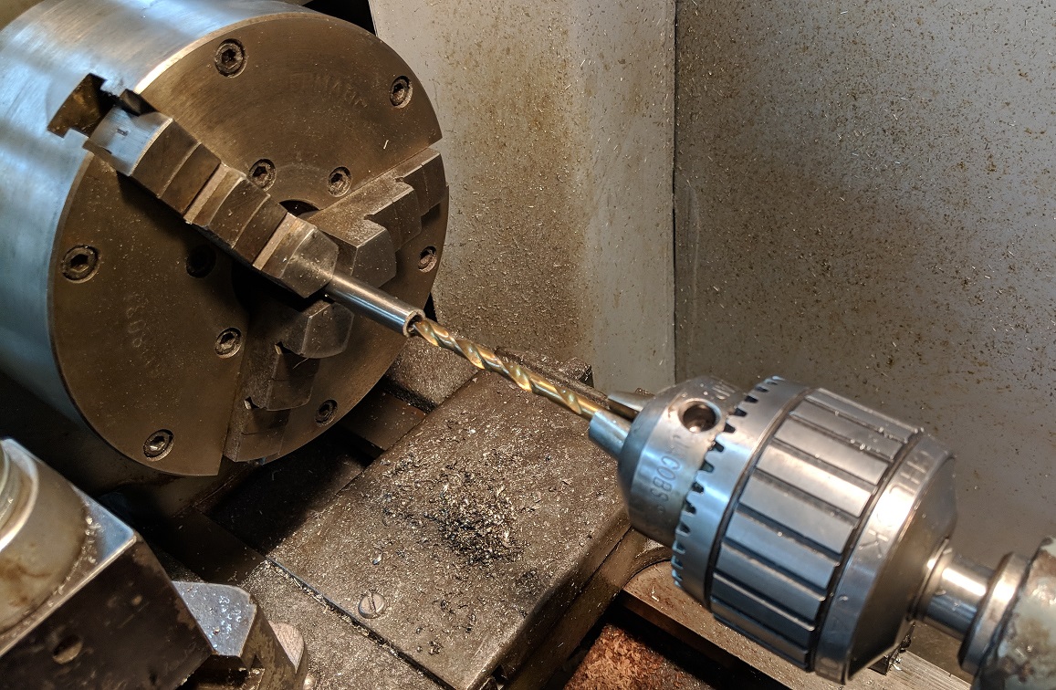
B. Making Parts Of A Tailwheel Hydraulic Actuator for Ray - This fall, I was headed down to see Ray before a work trip. He'd been having problems with is tailwheel strut hydraulic actuator leaking (leaking by the piston). I had the materials readily at hand, since I was planning to make a few of these for Kit #18 and a few to have in inventory. I decided to make up a new cylinder, piston and piston rod for Ray and bring it along. The first step was to cut the cylinders to length. That's a pretty easy task, just measure, cut with a band saw and trim in the disk sander: Here are three of them finished:

Next step was to put each of them into the 8" super spacer (really handy tool for machining round stuff!!) and put the correct sized holes in the correct places:


With that done, I threaded the rod onto the piston and placed it in the headstock. Then, I machined the other face of the piston and cut the OD of the piston true to the center of the piston rod (the correct diameter and concentric). With that done, I cut the O ring grooves and polished the whole assembly. Unfortunately, I forgot to get some pics of that, but I have more of these actuators to make (for Kit #18 and for inventory), so I'll have more pics then.
C. Hydraulic Repairs to 400 Ton Press - Not long after I assembled the hydraulic unit for the big press, and ran it a few times, I noticed several small hydraulic oil leaks. I hate oil leaks but, I walked around this problem and ignored it for months (easy to do when you're already so busy you also neglect to do timely blog updates).
The first leak I discovered (too late), was the pump shaft seal. On the back side of the tank, where the large belt pulley powers the pump input shaft, the shaft passes through a flange that is bolted to the pump. The pump is inserted into the back side of the tank and the flange, in turn, is bolted to the tank. Here is a side view of the pump:


The next leaks I discovered were the bolts holding the flanges onto the front and back of the tank (the return line flange and the pump flange). You can see the leaks here around the front (return oil line) flange:

The third leaks I discovered took a while to show up. When I remodeled this hydraulic unit, I had to expand the reservoir (tank) to get more volume of oil. It takes about 9 gals of oil to raise the press ram the distance needed to press the airplane parts. In order to get the extra volume I needed, I literally cut the tank in half horizontally and added 8" of height to the tank by adding 4 steel plates on each wall of the tank. Then, I had it welded up. Well, in 3 places in the welds, there are pin hole leaks and a very small rivulet of oil is leaking out. Here is one:


Well, I decided that it was time to start pressing some airplane parts soon and that it was time to tackle these issues and try to fix them - somehow. The purist in me wanted to take this whole thing back apart and tighten the be-jeezus out of everything. But, in order to take it all apart I'd have to empty the entire reservoir and the hoses and, without a doubt, I'd have more oil on the machine and the floor than into the storage jugs and pans. I really did not want to have to empty the tank and pull the pump.
So, instead, I climbed up and looked at the plastic catch pan that I had wedged under the leaky pump shaft seal. There was a fair amount of oil in the pan, but it had taken over a year to get that much oil in the pan. I figured, at that rate, it wouldn't be too big of a deal to just get on a ladder once every couple months and empty the catch pan back into the reservoir. And, who knows, when I start using the pump more, with heat from motion and use, maybe the seal will expand and seal more tightly again (hey - it's possible!). First leak - SOLVED!!
As for the flange bolt heads leaking oil, I decided to back each bolt out (one at a time) and wrap a large wad of Teflon tape around the shank of the bolt just under the bolt head. Then, I tightened them back down snugly. By doing this, I was able to significantly slow (and in some cases stop) the leak rate from these flange bolts. Second leak(s) - SOLVED!!
The tiny leaks from the tank welds I decided were not worth dealing with for the time being. Third leak(s) - SOLVED!!
In addition to the leaks I mentioned above - as I was climbing around the hydraulic unit, I noticed that there were also leaks coming from several of the threaded piping connections that I had put together to make this whole thing work. I tightened several of them as soon as I discovered them. Then, I went back and tied folded paper towels around each plumbing joint to use as a tell-tale. It looks kinda funny with all these white "band aids" all over the hydraulic unit. Look here:

So, I do realize that I really didn't do the correct fixes to these oil leaks. Essentially, I just did some temporary "bush fixes." I really want to use this press over the next several months, but if I tear it all apart to do the correct fixes it might be a very long time before I can get it all back together (my work sked and other time commitments being what they are). For now, at least, I'll be able to use the press and make some parts - particularly for the guys I'll discuss next in Para. D.
D. "Project X" - Making Test Parts For New Owners of Another Kit Aircraft Company - I was recently contacted by a couple gents who have purchased another, established kit aircraft company. They were wondering if I'd be interested in helping them form some parts for their project. I figured that this might be a great opportunity to collaborate with other folks who were trying to accomplish a lot of the same things that I am. We might be able to help each other out with problems we're having. So, I'm calling this "Project X" and I agreed to do whatever I can to help them with their project. The biggest challenge they are undertaking with their project is working to change the wing from a straight wing ("Hershey Bar") to a tapered wing design, like the Prowler. That is a sizeable undertaking - and will be very interesting to be a part of!
To kick things off, I decided to cut out a couple of sets of blanks for one of the nose rib dies that I made for helping Francis several years ago. For the Prowler, these would be made from 2024-T3 in 0.040" thickness. But, for their project, their ribs are formed from 0.032" material. Here is one of the blanks after cutting it out with the MotionMaster CNC router:

Once I had the blank cut out, I hit the die (form block) and the blank with some Pledge furniture polish. The Pledge has some lubricity to it and helps the parts and the rubber move without galling, ripping or tearing (I learned that from, and credit to Brian Carpenter):


Here is the wear pad with some Pledge sprayed onto it:


Finally, I turn on the hydraulic pump motor and run the red platen (called the bolster) up into the rubber box (black box above the blue wear pad). The force of the press (400 tons) is converted into pressure (per square inch) of the blue wear pad onto the flat blank and forces it down over the die (form block). When the ram is run back down and the pressure is released on the rubber, I take out the form block with the newly formed part on it. (The first video link below shows this process as I actually do it in the press, check it out!). Here is what two of them looked like after forming and some hand work:


I trimmed the tip of the nose rib on the bottom right - just an example as to how some manufacturers avoid having to deal with the significant forming issues that occur in that area.
The guys liked my process and have asked me to make some mid-ribs for them next. They emailed me the CAD files for cutting the rib blanks and I should have the form blocks that they made up in a few days. The next time I get home from a trip I will cut the blanks and press them out. More to follow.
Part 1 - https://www.youtube.com/watch?v=yDCJAnK-jeo
Part 2 - https://www.youtube.com/watch?v=mfN2ATu_saQ
(These videos are also posted to they Prowler YouTube Channel I mentioned earlier.)
E. Finally Completed Dies For All the Outboard Nose Ribs - Working with the fellas above got me motivated to get more of my dies fabricated so that I can press out some Prowler wing ribs. Until now, I had made the two tip rib dies, and 4 nose rib dies for Francis (total of 6 dies). I had the chunks of 1" thick aluminum laying out (for the past 4+ years) ready to make 4 of the remaining nose rib dies for the outboard wings. If I could make those 4 dies and then the last two remaining large dies, I have all the outboard nose rib dies done. The goal was set! I had a couple of nice stretches of days off in Feb, so I tackled those dies. Here you can see 4 of the 6 remaining dies that I needed to finish - they are the ones that are raised up and sitting on the wooden patterns:


So, if I'm going to use the same die to press BOTH ribs - what to do with the rib blank that does not have the lightening hole cut in it??? Without some how covering that pocket in the die, the rib without the lightening hole would have a big dimple pressed into it when the rubber pad presses down on it. The answer is, I need to fill the pocket. So, I machined a disc that will just drop into the pocket and fill it, but come back out easily. Here is the result:


I machined out the other wing junction nose rib die and decided to just use the same disc for both dies (it was a little bit of a challenge to make that disc without any holes or other features to hold it rigidly while machining it - how do you think I did it??). With that die complete, I had finished making all of the nose rib dies for the outboard wing sections. Here they are all together:

With those completed, I was trying to decide which way to go next. Should I start on the outboard mid-rib dies, or the wing center section nose rib dies? Then, it occurred to me that I have to make a set of the dies to form the cockpit floor stringers (from the main spar back to the aft bulkhead that attaches to the aft spar). Kit #18 in my office needs a set of those to help make the kit complete. But, that brought up a new problem - material to make those from. Those parts are 9+ inches at the widest point and are nearly 30" long!
I have been buying 1" thick aluminum plates/bar from a local surplus house - when I find them in sizes that I need. They charge me $3/lbs for these pieces but, finding a piece that wide and that long was hit-n-miss at the surplus place. I was chatting with my machinist buddy about this and he offered to check what his metal supplier charges for aluminum bar. Turns out, he could buy me a new 12 ft stick of 1" x 10" aluminum bar for $2.20/lbs!! Holy cow - the size I need and less expensive too!! Score! Well, less expensive is a relative thing, I guess - cuz, there are a lot of those "lbs" in a stick of aluminum that size. To be exact, $320 worth of "lbs". But, I wouldn't get it cheaper anywhere else, so he ordered one for me and two days later it was in my shop:


F. Ray's Work on MLG Torque Tube Pivots - In previous updates I reported on an issue that Ray was having with his MLG torque tube pivots. He had discovered the bearings that were pressed into the pivot links were not properly staked into the link and eventually wiggled their way out of the pivot link. His fix was to cut access panels in the tops of the wings and gain access to the pivot links via the access plates that he'd also built into the tops of the torque boxes. Here's what that looks like:


I think I've mentioned in previous updates that Ray is in the process of moving out of his home & hangar in Thousand Oaks area of Southern CA and into their new home in near Bend, OR. I got George's old Prowler Trailer back when I moved N611GM back from EZ last fall. In Nov last year, I drove the trailer down to Ray so that he could use it to pull his Prowler up to Bend. Over the winter, Ray has done many modifications to the Prowler trailer to make it easier to load and unload an aircraft. I have not seen these yet, but I hope to meet Ray near my place on his drive up to his new place.
G. An Update From Francis - Francis the "FrogProwler" keeps jumping right along on his Prowler project. In a recent update he emailed to me, he says:
Hello Todd,
After some hours deburing holes😅, And ,some dimples😅, After ....$#&%@}{! PR!🤭😱🤢 [I think he's referring to "ProSeal or something similar - he included these pics]
After some hours deburing holes😅, And ,some dimples😅, After ....$#&%@}{! PR!🤭😱🤢 [I think he's referring to "ProSeal or something similar - he included these pics]


TIP : Put on about 5 layers of nitrile gloves [on before you start working with the ProSeal], like that you can [have] clean [hands] in 10seconds (because the humidity of hands for putting on [new] gloves makes it difficult..)🤬😡 But leave [to remove] a layer is easy!😉✌👌
I learn too, how to fill up an empty plastic tube cleanly and with out "bulle d'air" [air bubble] for applying this fu..ng PR with the pneumatic gun. [See, he really likes it!!]
When i do that [again] ,I'll try to film it to explain!!
When i do that [again] ,I'll try to film it to explain!!
And, I [am also] working on the landing gear over center links axles [pivot links].
Thanks very much to RAY for his clever [idea] to open trap doors [access panels in the] landing gear box lid!😘
I hope everybody is ok with you and the Prowler guys!
Here is a pic of the access panels that Francis made using Ray's idea:


OK, that's all for this update. I have a kind of big project to report on that I started almost a year ago. I'll probably post that update next (soon). Then, shortly after that I'll follow with another blog update that will have more Prowler related items. Thanks for keeping up with the Prowler blog. I hope everyone is off to a great 2019 and hope everyone is ready for a great summer. AirVenture is only 17 weeks away!!!


No comments:
Post a Comment