Hello Everyone!
I gathered enough stuff the past several weeks to put together a decent blog update. I have a little time available right now, so let's get'er done! Here's what I have for you:
1. Update on Bryan's Prowler
2. Update on Francis' Prowler
3. Francis Needed Fuselage Former #8
4. Aft Spar Bulkhead Fabrication
5. Rebuilding My 1.5HP Bridgeport Mill Head
6. Local EAA Chapter Work
Before I start the update, I wanted to share some personal news with you. I recently received my special issuance medical certificate from the FAA AMCD:I can now begin the process of going back to work! I still have to get another 1st class medical and a return to work authorization - but I should go back onto the company's payroll sometime in very early May! So, I guess it's time to start studying and getting ready for training so that I can get re-qualified on the "day job" aircraft. I will likely be busy with training in May-June and should be able to be back to flying the line by July (hopefully). I may not have a lot of time for Prowler Aviation work for a few months, but I will keep up and do my best to support current builders.
On with the update!
1. Update on Bryan's Prowler - In the last update, I mentioned that Bryan was waiting for his FWF solution from AutoPSRU's. Well, he is still waiting, and he is still working on getting the airplane ready for it's new engine instead of the Deltahawk Diesel that he had originally designed the airplane for.
Since it has been so long since he originally did his instrument panel, he decided that an update was in order. Here is what was left when he yarded the out the old panel:Here is the "pile" of stuff that he as removed and plans to update, replace, or completely just delete:Another view of his "out with the old, prepped for the new" campaign:Here is the cockpit after even MORE removal:With all that old avionics removed, he has begun the new "plan." So, starting with the instrument panel, here is what you will see (so far) when sitting in the seat:And, here is the reverse side of the instrument panel:Forward of the instrument panel, he has created an "avionics bay" that will be between the instrument panel and his forward baggage compartment (Bryan chose to not install a fuel tank aft of the firewall). Here is the forward side of the avionics bay bulhead:Since the diesel FWF that he originally planned required a 24Vdc system, he designed the
airplane to be a complete 24Vdc electrical system. Now that he has a
new plan for the Honda engine, a 12 Vdc system is all that is needed.
This has made the Vertical Power systems a possibility and he has
decided to go with exactly that.
Then, to complete the setup, here he is holding the forward bulkhead of the avionics compartment in place (this is also the aft bulkhead of the cargo compartment):Here are a few other tid-bits, in no particular order. Bryan found a MLG uplock that has an electric release! All the current builders have been using these aftermarket car door latches as MLG uplocks since Ray came up with this for his plane. It makes sense, as they are usually rated for pretty sizable forces (so that car doors don't pop open in accidents):He has also replaced the flap actuator with a newer linear electric system:This is a repair to some battle damage that the aircraft received:He had been working on a hydraulic cylinder off of his Aerostar last winter. There was some spring preload that he hadn't relieved and the ram shot out of the vice and across the shop, hitting his Prowler mid empennage! This is what it looked like after the damage:That looks like an outstanding repair. It really sucks that this happened, but I am glad it could be repaired and it turned out looking great. I told Bryan that calling this "battle damage" gives him more swagger when telling war stories!
Overall, you are doing outstanding work on your plane, Bryan! It is looking great!
2. Update on Francis' Prowler - You may recall in the last blog update, I had made CAD drawings for the fuselage jig and sent them to Francis. He took them and ran with them. He has been making fantastic progress. It appears that his kit was missing some of the longer 2" C channels for the empennage keel and cockpit side wall longerons. I think this is the setup that Francis made to fabricate some of those channels:This looks like he is fitting a splice into the cockpit side wall longerons. That part 24102 is the upper longeron splice (or coupler) and is 2"OD to fit inside of the longeron that is 2" ID:Possibly the other upper longeron. The end of the flat aluminum bar you see is the stiffener added on the inside of the upper longeron to strengthen both sides of the cockpit wall:The ends of the stiffeners are tapered to reduce the concentration of skin stresses in one specific area on the longeron that could cause stress risers and cracks. This technique helps to spread the skin stresses over a larger area:A side view:This is the vertical post of his fuselage former. He as mounted the aft 1/2 of the lower rudder hinge to the vertical post. Eventually, he will build the empennage out to this hinge and it will be the main, aft point that the airplane will be supported by the vertical post:
To be prepared for possible adjustments, he has made the aft post moveable (slide up/down) so that it can be position where needed to support the aft end of the aircraft tail:Here is the vertical spar rudder mounted to the lower, aft rudder hinge:And, here are two fuselage longerons added to the jig with a fuselage former #6 and the forward vert stab attach bracket:Here is the same area viewed from a different angle:A side view:Finally, two pictures of the entire aft end of the fuselage attached to the fuselage former that is the back wall of the cockpit:From the other side:A closer look at the forward spar attachment of the vertical stabilizer:Here is a pic of the aft empennage. The open space here is the area where the horizontal stabilizer and will eventually sit. In the very back you can see the aft spar of the vertical stabilizer. But, there is something missing back there! Any guesses?What's missing is the very last fuselage former (bulkhead). It's not very large, but it covers the forward side of the aft vertical stab spar and has it flanges facing aft. It's not there, because somehow it was missing from his kit. He recently asked me if he could get one of them from me. I certainly wanted to! The problem was, I really didn't have one in inventory. The only one I had was from kit #18 and I preferred to keep all the parts of that kit together. Even worse, I did not have anything to even make the part from. So, I had to get busy - I didn't want to be the hold-up for this project!
3. Francis Needed Fuselage Former #8 - After Francis asked about this aft fuselage former, I went and dug out everything I could find that I had with regard to this part. I grabbed the part out of Kit #18 (green), I found an old plywood pattern (or maybe it was a forming die - not sure) and I found what I think was forming die made from Bakelite (brown) that George made but never used:
Then, I fired up the computer and found a CAD drawing for this part that I had made years ago. I believe that I used the Bakelite former as the basis of my CAD drawing and cross-referenced it to the lower portion of the aft vertical stab spar. Next, I found a suitable piece of 1" thick aluminum bar and cut out a ruff shape to mount in the CNC mill (on the right, above).
After an hour's worth of CAD and CAM work, I headed out to the shop. I mounted the blank in the mill and cut out the forming die in a few hours. Here's the die (form block):The next day, I went out and took some measurements off of Kit #5 to determine the rivet spacing on the skin around the aft fuse former:I needed the rivet spacing so that I could lay out the pattern for cutting the flat blanks in the router. You can't put a slot to make tabs in a place that you need to put a rivet, so planning is key here. After determining where the place the slots, I finished making up the CAD pattern for the part. The first version looked like this:
Next, I CAM'ed the part and took it out to the big Motionmaster router. After a bit of set up (and a lot of shaking out the cobwebs from not having used this machine in over 2 years) I finally got it ready:And, started making some chips:Here are the 1st two forming blanks that I cut. They are still on the router table after cutting:I pulled the blanks out and cleaned up the edges with a file and some Scotchbrite. A short time later, I had the first blank on top of the die and in position with some pins (made from roofing nails). Here is the flat blank on top of the die and ready to go into the 400 ton rubber pad press:This is what it looks like from the bottom side.Notice that the gullets (innermost, round part of the slots) are separated a
little ways from the forming die. This is important because allows enough of the shear web material to bend in the direction of the flange and it gives
the part (after forming in the press) some rigidity. In other words, the gullets are in the flange and not in the shear web (flat portion) of the part. If the slots were
cut deeper, once the part is formed, the part would still be weak and
kinda "floppy."
Notice also, that the width of the slots in the pic above are all the same over the entire part. This was a mistake. In the lower corner, where the bend radius is very tight, the metal in the flanges has to "have someplace to go" - for lack of a better term.
If you need a visualization of that - then this pic shows exactly what I mean:Notice how the tabs interfere with one another and overlap. That is not ideal and does not make for a good looking part. The problem is, until you form the first part, you really don't know how much material to remove from each slot. It's really just a guess, and then you refine your blanks for the next batch in an iterative process.Here is the same part, after trimming the tabs and trying to widen the slots a bit.With a bunch of hand work and filing with a small, round file, I was able to clean these parts up and make them look much better. But, the idea is to not have to do a lot of hand work. Here's another view:Here is the part after I cleaned it up and did a lot of hand filing to get the slots more uniform and the gullets looking more rounded and smoothed:Notice in the areas where there is not a large bend radius, the slots remain very uniform and clean looking:So, I took some ruff measurements off of the first part and used that to refine the CAD drawing for these forming blanks. In the pic below you can see how I widened the slots and made them more triangular shaped so that they would look a lot nicer as they came out of the press:When I press these parts, I use a little furniture polish (lemon Pledge or similar) to give the aluminum some lubricity and allow the urethane to slide over and not pull on the aluminum blanks. In doing this, the urethane abrasion pad (blue) will seal to the bolster (red) during the pressing operation. In fact, as the air is purged, the press actually "farts." Then, when the bolster moves back down, the pad will stay "suctioned" onto the bolster and look like this:That bump in the middle is the die and the part sucked down to the bolster! Using the revised blanks, you can see that the second batch of parts came out looking a lot better, right out of the press:There are still issues with the slot widths and the gullets tend to "poke" out a bit. But, a little hand forming and filing cleaned these up quite nicely:I took more measurements of the parts after the 2nd pressing operation and my 3rd revision will be made from the pic below. In fact, I have already made these changes to the CAD drawing for these forming blanks and the next time I cut a set, the changes you see below will be incorporated:
In the end, I came up with one part that is pretty much junk (first one that I formed). But, the 2nd and 3rd parts came out acceptable. Here you can see part #3 on the left, the forming die (second from the left), part #1 with flanges up and part #2 on the right:It is really satisfying and gratifying to be able to form these parts from scratch in a relatively short period of time. It will be even faster, once I all the dies made and all of the flat stock CAD work completed and tested to get the "kinks" out.
It took me a LONG time to build this part forming capability - but it does work! And, it works very well! I guess that's why this process (the Guerin Process) was used almost exclusively to make nearly every single airplane in WWII. Pretty cool!
Here are the two best parts that I formed. The one on the right was the one that I ended up shipping to Francis. The one on the left will remain in inventory - in case another builder needs one:
I will also keep the first one that I formed around and probably hang it on the wall as an example to remind me of the fact that this flat stock design has a learning curve to it. The next time I make a part with such a tight bend radius - I'll remember to shape the slots better the first time!
4. Aft Spar Bulkhead - In the last update, I talked about making this die to form the fuselage bulkhead that is attached to the aft spar beneath the cockpit floor. It is a big, thick die and making it was out of the "norm" compared to all the other dies I have been making. Here is what it looks like:Before I put this die on the shelf and added it to the collection of dies that I made last year, I decided that since I had already swept out the cobwebs with regard to running the Motionmaster router - I had time to try to make this part. Really, I wanted to see if (and how well) it formed this aft bulkhead. The first step in that process was to go out to the "Sea Prowler" and measure the rivet spacing along the lower flange of that bulkhead:It looks like it is 1". And, that is important because before I can put slots into the flat stock CAD drawing to make tabs along the curved flange - I have to know where the rivets will be. You don't want to have a slot show up where a rivet needs to be. Adding this rivet placement into the drawing looks like this (small points are the rivet locations, the bigger dots are the slot placements):In this case, I designed the tabs to each hold 3 rivets with a slot on either side of those 3 rivets. You'll see what these slots end up looking like in the pic below after it was cut out in the router.
With the CAD and CAM work done, it was time to go set up the router table. The piece of stock that I am going to cut this from is at the back. The other pieces are simply holding down sheets of poly that help to keep the vacuum table from "leaking" too much and keeps more hold down force on the piece of stock that the part is being cut from:
SIDEBAR ---------------------------------------------------------
I used to just lay the 3 mil poly on the table and the vacuum will suck the poly down to the spoil board. It works great to "contain" the vacuum and focus it on the stock that you're cutting parts from. But, the poly sheets do not always lay completely flat, and the air that I have blowing down onto the table to blow the chips away from the cutting tool will sometimes lift the poly up, off the table.
One day, the router caught a piece of the poly sticking up above the table - the result sounded like a gun shot that wrapped the piece of poly around the router in about 1/100 of a second (the router turns at ~10,000 rpm)! Nothing was damaged, but lesson learned. Now, I always lay small sheets of aluminum over the poly to prevent a repeat of that day!
----------------------------------------------------------------------
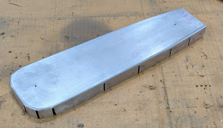
Here is the flat stock that will get placed onto the die and shaped in the pressing operation. The tabs are on the top, but that is actually the bottom of the part as it is placed on the airplane:Here is the flat stock placed on top of the die and held in place with 4 pins:
Here is the part directly out of the press:The part turned out very well! I am, overall, very much pleased with how it turned out on the first attempt! I did find several things that I will do different on the next part, but it looks like the die will work to make good, serviceable parts! The major thing that I have already changed is that the slots for the tabs were too deep. The gullet of the slot is too far into the flange and the part is a bit "floppy." I shortened the slots and when I cut out the next flat blank, the next part will have much more rigidity.
Another "failure" on this part was that I forgot to turn on the table vacuum when the router started and one of the two large holes came out mis-formed (the stock moved on the table as the router started cutting). All of these are mostly "aesthetics" and would not affect it's serviceability. This part could be used - it would just have these minor imperfections. I'll hang on to it, for now.
Next, I compared the bend angle of the lower flange. It is supposed to be little bit less than 90 degree to the inside of the bulkhead web (about 86 degrees). Here is one end compared to the inventory sample that I had:You can see that the bend angle is much better than the sample that I had. Below is the other end lined up to compare the lower flange bend:
Here, again, the bend angle turned out pretty much spot on. The nice thing about tabs, is that they can be manipulated a little to parallel the skin panels during installation. If the part had one long flange, it is not so easy to manipulate the bend angle at any given area.
The one thing I noticed in the pic above, the bulkhead looks slightly taller. The top flange (on the right in the pic above) is lined up. The bottom flange bend looks slightly more to the left making the part a little taller. However, I double checked it to a drawing that I got from George, and it appears to be the same dimensions as what the drawing calls for - so, I'm gonna go with it for now. (If I find out later that it is too tall and it won't fit, or the skin won't flow well, I can re-cut the lower flange on the die and make it correct.)
All-in-all, I think it was a satisfactory outcome! Now that I shortened the slots about 1/8", I'm confident that this die will make very good parts - especially if I remember to turn on the table vacuum before the cutting starts!!
5. Rebuilding a 1.5HP Bridgeport Mill Head - I have a Bridgeport manual mill with a 2J variable speed head and a 1.5HP motor that was my very first "big" machine purchase. I use that mill a LOT and it's been a good machine - but, the head always made a lot of noise while cutting in low gear. Then, several years ago, I did some work for a local machine shop and they had a similar 2HP J2 head laying on a parts pile. I asked about it, and they gave it to me.
In previous updates I showed pics of restoring that 2HP head and eventually installing it on my Bridgeport mill. The rebuilt head has been working OK, but I recently discovered that the spindle in that head is, most likely, bent about 0.01" to 0.015". It was causing the mill to "bind" as the spindle rotated. During vertical cutting with the quill feed, the down-feed would "pulse." You could feel the quill moving down in pulses as you pulled on the quill handle.
Since the head swap, the original mill head was mounted to a storage cart awaiting a rebuild of it's own My plan has always been to rebuild the original head and then re-install it on the mill. I pulled the spindle out of the original 1.5HP head and installed it on the Bridgeport with the rebuilt 2HP head on it. The pulsing problem seems to have gone away. So, now I have a good head on the mill to work on projects. But, I still want to rebuild the original 1.5HP head. So, I got started one day! I just started tearing things apart. The first step is to pull the motor off, then pull the bearing cage off that holds the top end of the spindle:
Then, you remove the variable speed crank on the front and some bolts in order to pull the belt housing off. This exposes the variable speed pulley on the spindle and the back gear and timing belt (behind and below the pulley):The top half of the variable speed pulley just slides up and off of the spindle shaft:After that, there are several steps to remove the items above the main body of the mill head. There are also a bunch of things to remove from the main body itself. After a few evenings, I ended up with the main body pretty much stripped down and ready to start the rebuild process:
There are two main things to notice here. First, these are large (made in the USA) castings from an almost bygone era. As such, when stripped bare, they have a ruff finish. So, back in the day, when these were made, they slathered them with body filler and sanded them down to get nice, smooth and glossy finish. Well, after 60+ years of heat, oils, coolants, and all manner of abuse, these things begin to degrade and the filler starts to chip off. You can see that all over this piece.
Second, ever since I got this machine, it has had part of the casting broken off where there is a "bump out" (on the lower right side of the quill) that is designed to hold a 5/16" rod. This is so that you can mount various indicators or tooling for all sorts of different jobs. You can see how this was broken off in this pic:
What I suspect happened here, is that the original 5/16" thumb screw that was used to "jamb" the rod on the inside of the "bump out" got stripped out. Then, someone tapped that hole out to 3/8" so that they could still use it. At some point after that, some "armstrong" machinist cranked down on that 3/8" bolt so hard that it pulled the cast iron "bump out" apart. This is just my theory, considering how it looks like this part failed. But, I'm not certain.
Anyway, I wanted (needed) to use this feature and at one point I drilled and tapped a small set screw in the front of the mount so that it could hold the 5/16" rod (there was a small area on the bottom of the rod hole that was not broken off and I could hold some small dial indicators, etc.)
How to fix this? Well, there is basically brazing and welding (maybe silver soldering, too?). I have done braze repairs to a few things lately, and they didn't turn out too bad. The problem with brazing is that you have to pour a LOT of heat into the part that you're brazing. I was concerned that this much heat might warp the quill housing (the big bore in the main body) and cause it to become unusable (the quill would rub and stick).
I sent some pictures and called my dad to see what he thought of it and if welding was an option (he's a retired Ironworker who's done a bit of welding in his day). He felt that because welding is very localized heat, that it could be welded - as long as it was done in short bursts with time in-between passes to allow for cooling. He also recommended this:
That is a brass insert that I fabricated and put through the existing portion of the hole that was not too damaged. Because it is brass, the high Nickle welding rods would not stick to it (brass doesn't have any iron in it and dissipates the heat too quickly). As the bump out area is built up with weld, it would naturally create a bore (hole, tunnel) that would be aligned with the existing, undamaged bore. This was genius! It worked awesome! Thanks, Pop!I put a wet towel in the quill bore to help keep the heat down. Then, I made several welding passes with cool down breaks in-between and built the area all back up. When I had enough material added back, I started shaping it with a small grinder blade. It turned out fantastic! Later, I drilled and tapped the bump out for a 5/16" socket head cap screw:You'll also note in the last few pics that the old body filler is all removed from the main body of the mill head. I decided to just strip it all back down and I am going to re-coat it with a very light coat of filler material and some Hi-build primer. Here is the main body, taped off and ready for primer:And; from the other side:Same pics, but with a first coat of primer on the main body:Since I may not get to this project again, for a while, I wanted to get this bare metal sealed up so that when I do get back to it, the piece hadn't flash rusted:The next step with this will be using small amounts of body filler to fill up the biggest, roughest parts of the casting. Then, it'll be a good smooth sanding and finally paint. I already purchased the paint from the local paint shop. It's a good, oil resistant, glossy acrylic paint that should look really good! More later!
6. Local EAA Chapter Work - Before our local EAA chapter meeting this month, a couple of us got together to do some spring clean up. The chapter has two small Quonset huts at a small airport (Benton Airpark):
The chapter president usually keeps the place up, but he has,
unfortunately, suffered a stroke recently and is still in rehab. So, I
loaded up the lawn tractor, the weed whacker and the chain saw and met a
couple other guys up there to get it looking good for our monthly meeting:This area, between the trees and the fence is always grown up the most with thick grass an a lot of weeds:
It cleaned up well, both inside and outside the fence:Everyone got to drive up to the Q-hut looking all "spiffy" for the meeting:That is all for this update. Hope you enjoyed it and I will post again, probably after AirVenture in Jul. Thanks for stopping!
Sunday, April 27, 2025
Subscribe to:
Post Comments (Atom)











No comments:
Post a Comment