Monday, July 3, 2023

Fabricating More Prowler Parts, Builder Updates and Some Shop Projects.

 Hello Everyone,

Happy Independence Day to each of you!

I hope your summer is off to a great start!  As for me, I managed a quick trip to WI in early June to open up my property there, get the grass mowed and open up the RV for the summer.  So far, I only found one big problem there - a 50 amp breaker that failed.  Otherwise, the RV and the property are in OK shape!

Well, AirVenture is just around the corner!  I'm finishing my last few days of work (day job) for the summer and looking forward to having most of July and August off thanks to two strategically placed weeks of vacay!  We won't have as large of a "crew" at AirVenture this year - but most of the family will make it for a day, or two.  As always, I'll have an update this fall with pics and vids from the "Big Show" this year.

On a recent trip out of SFO, I got a pretty nice view of Lake Tahoe.  This is taken from the south looking north.  The airport you see is the South Lake Tahoe Airport and Emerald Bay is just to the west of that.
Time is short for me right now, but I'm gonna try to pound out this one last update before summer takes over all of my time.  Here's what I have for this update:

Prowler Stuff
1.  Engine Compartment Mock-up (Longerons and Bulkheads) -
2.  Builder Update From Francis -

Non-Prowler Stuff
3.  Pexto G-52 Sheetmetal Shear -
4.  Finally Finished The Hardinge CNC Lathe -

Let's get right to it!

1.  Engine Compartment Mock-up (Longerons and Bulkheads) - I have been trying for years now to get a final solution set up for the Prowler FWF package using AutoPSRU's products.  Stuart and Larry have built an engine mount and placed it onto a Prowler firewall.  But, the progress has stopped waiting for me to get them set up with a Prowler engine compartment.  We need to have a close approximation to the engine compartment that I want to use, so that we can figure out exhaust routing, a possible cooling inlet and a few other structural issues.

Well, the first steps to getting an engine compartment built (assuming the firewall is in place) are to get the forward engine compartment bulkhead formed and make the longerons (and associated brackets) that run from the firewall to the forward engine compartment.  I recently had a request from Vaughn for both of these items - which I showed in a previous update.  The forward bulkhead for my iteration of the Prowler is "complicated" and I'll cover that in a minute.  But the longerons are pretty straight forward. 

While I was in that "mode" of forming the longerons for Vaughn, I used the last of the channel I had to make up a set of engine compartment longerons for the FWF mock-up.  Actually, one of them that I am using for the mock-up set was one that I accidentally broke a flange on while forming them for Vaughn.  When I got down to the last 2 longerons, I didn't have enough 2" channel left to make full length longerons.  But, I did have some pieces that I could put together and make a couple longerons that are good enough for an engine compartment for the FWF mock-up.  So, I made up some 2"OD channel and riveted the pieces I had together.  Then, I shrunk the flanges to make the last two longerons.  Here's one side of these:
And, the other side:
Here are all 6 longerons that will be used for the FWF mock-up engine compartment:
OK, that was the easy part.  Now, about the forward engine compartment bulkhead (the part that I refer to as the "horse collar").  Here's the issue - I can't use the existing form block to make the horse collar, because in order to fit the AutoPSRU reduction gear into the engine compartment, I had to make it 1" taller than the ones that all the previous Prowlers have used.  What this means is that I have to make a new form block that I can use to fabricate a horse collar that will work with the AutoPSRU gearbox.

That, by itself, is pretty straight forward and can be done pretty easily if you're just fabricating one horse collar.  But, the issues with fabricating this part get bigger when you think about trying to fabricate horse collars in a production environment.  What technique is used to form the part, directs how you make the form block.  The horse collar is actually a pretty complex part to form.  The outer flange of the part varies in width and the angle it makes with the flat part of the bulkhead changes as you move from top of the part to the bottom.  That makes it tougher to get it done right.

I would like to form this part using 2024-T3 in my rubber pad press.  The problem with that is, the outer flange would have to be "tabbed" in order to form it correctly in the press.  The tabbed flange would not be a problem if it was permanently riveted to skin.  The problem there is, all the panels of the engine compartment are removable and the tabbed flange of the horse collar would not be rigid enough to give the engine compartment the necessary strength it needs.

I started down the road to making the new form block for the horse collar.  I bought a piece of 1" thick HDPE sheet.  Then, I printed the outline of the flat portion of the horse collar from my CAD drawings and traced them onto the material:
Here it is in the mill:
Both halves traced onto the one sheet of HDPE:

For now, that's a far as I've gotten.  I still have to decide how I'm going to make these in production so that I can make the correct form block for that.  Stay tuned.

The alternative to form this part is to make it from 2024-O material - pressed and formed with a solid outer flange.  But, then it would have to be heat treated.  Heat treating is another logistical and financial step required to make each of these parts that I'd rather not have to do.  Right now, I'm leaning toward forming the part from 2024-T3, tab the flanges, but then go back and rivet in a "liner"onto the part that would make the outer flange act like a solid flange.  I'm still experimenting with this.  More to follow.

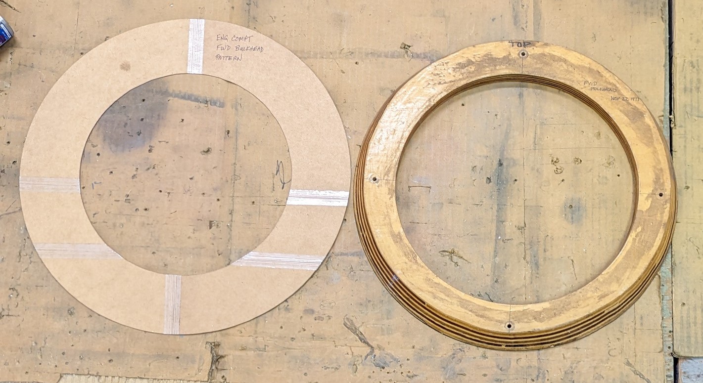
Beyond the horse collar, there is one other bulkhead that is needed right behind the prop spinner.  That bulkhead will need to be formed in the same manner that I decide to make the horse collar - because it too has a flange with a varying width and angle.  This part is the same size that it has been for all Prowlers up to now.  Here is the form block for that part that came from the original Prowler Aviation:
I make a cardboard template for the blank that will need to be made using this form block:
Making both these bulkheads will be on the top of the list, when I get back into the shop this fall.  Stay tuned.

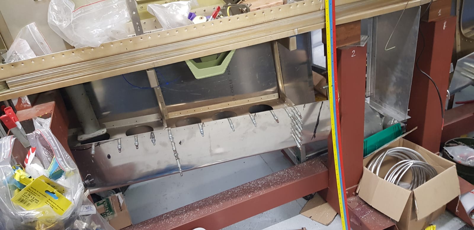
2.  Builder Update From Francis - Once again, Francis has been busy doing awesome work on his Prowler project.  He has shared the following pics with me.  I will do my best to explain what I think the work is that he's been accomplishing.

Last March, Francis wrote me asking about forming the leading edge of the wing skins.  I sent him the dimensions of the apparatus that George made for forming the wing skin leading edges.  Here's the tool that I got from George for forming them:
It's essentially two 9' long 4x4's with blocks mounted to one of the 4x4 on each end to prevent over clamping.  I assume that he opened the clamp as wide as possible and then (with a helper) wrapped a flat sheet of skin material like a taco and stuffed it into the clamp.  Then, it would have been positioned correctly and the nuts on the long threaded rods would have been turned down to clamp the material and form the leading edge bend.

In the end, Francis decided that he wanted to try to use the vacuum forming technique.  I have also used that technique to form the leading edge of the vertical stab skin in the past and it is a very effective way to make long, relatively sharp bends in 2024-T3.  It really is amazing how much force a normal vacuum cleaner can make when the small differential pressure is leveraged properly!

It looks like, to get started, Francis used various boards and metal to start to get the aluminum skins to form around a piece of tubing with the correct size radius that he wanted for the leading edge of the skins:
Then, to apply more force and get it to be more uniform along the bend, he put several boards on the top of the skin and used a bottle jack to press the skins down along the piece of tubing:
With that done, he could tape the ends, hook up the vacuum and pull the material down around the tubing to complete the forming of the leading edge:
With the skins formed, the next step was to fit them and get them cleco'ed to the wings.  Here is the right hand inboard skin (looking at the top):
The right hand skin looking at the lower side:
The left hand inboard skin looking at the lower side:
And, the left and right upper side of both inboard skins cleco'ed in place:
That is outstanding progress!  I like the covering on the joystick!  I wonder if it is there to protect the joystick, or someone's head?

Next topic.  Francis liked the uplock system that Ray designed using aftermarket automobile door latches.  They really are a great choice for this application.  (1) They are designed to hold a car door closed under pretty extreme forces; (2) They must be aligned when installed, but they sort-of self align while closing each time; (3) they are relatively inexpensive; and (4) they are fairly compact.

Recently, he emailed Ray and I to ask about mounting the stud in the axle yokes that work with this uplock design.  Ray was able to answer his questions and it looks like he got a successful installation.  I believe what Francis is capturing in this first few pics is his set-up for fixturing a hardened drill guide in the correct location to drill the hold for the uplock stud in the end of the axle yoke.  He clamped the end of the yoke to one flange of a large aluminum angle and then clamped his drill guide to the other flange:
Same thing, just a different angle:
After drilling, he tapped the hole for the stud:
Here it is with the uplock stud installed:
And, here is the latch placed over the stud roughly like it will sit in the gear well:
Nice work!  Soon, we should see pictures from Francis of his landing gear struts mounted in the wings!

Actually, maybe he already has!?!?  Because, this next pic slows the marking paint that he put on the ends of the anti-torque links:
And, it looks like he used this marking paint to leave a mark on the inside skin the of upper side of the wing so that he would know where that point on the anti-torque links would need more room to keep from hitting the skins.  Then, it looks like he pressed some aerodynamic "bumps" that he is going to place into the upper wing skins so that the MLG struts will fit without pushing up on the wing skins.  Have a look:
It looks like he has already roughed in a hole in the skin for the anti-torque links to go into.  Here is a closer view.  It looks like he also made himself some kind of a form block and press plate to make those "bumps".  Nice work!
As always, thank you for the updates, Francis.  I really appreciate you sharing this info with me so that I can share it with the rest of the folks interested in Prowler construction.

That's it for the Prowler related stuff in this update.  The info below is not directly related to Prowler building.  So, feel free to depart the AOA now if you're not interested in some of my shop projects.

3.  Pexto G-52 Sheetmetal Shear -   I have had this Pexto sheetmetal shear for well over a decade now and for all that time, it has not been usable.  I got this shear pretty inexpensively, but it was set up to be used as a pneumatic shear and it was not operating.  This is what it looked like when I got it off the trailer and into the shop:
Right after getting it into the shop, I stripped nearly all of the pneumatic operating components off of the it and started laying plans to rebuild it as a manually operated shear (actually, foot operated) - which is the way it was originally designed and intended to be used.  More on that in a bit.

Well, it didn't take long to figure out that this thing was HEAVY and moving it was gonna be a pain.  Things in my shop need to be mobile so that I can shuffle things around if I need to.  So, the first time I needed to move it out of the way, I went all-in and built a mobile platform for it and mounted it on the mobile base.  I'm pretty sure I covered that in an update at some point - a long time ago.  Here is what it looked like after installing it onto the mobile base:
At this point, I could move the shear around the shop but it was not much more than a huge paper weight.  When it was converted to a pneumatic shear, the foot treadle (bar that you step on with your foot to operate the shear) had been removed (and was not anywhere to be found in the shop that I moved it out of).  Also, the springs that allowed the blade on the shear to move back up after a cut were removed and gone.  In addition to that, the clamp bar across the front had been modified and the original manual handles that clamped the material down to the table were yarded off and gone.  So, all this was going to have to be replace.  But, with what?

During the last 10+ years, I have been doing Google searches and scouring equipment auctions and FleeBay for a similar cheap and "ratted out" shear that I might be able to rob parts off of.  But, there just aren't any out there - at least not that I could find.  So, I could never make any progress to get this project done.  [Incidentally, I also found out that you can buy this exact same shear from Roper Whitney (they bought this line of shears from Pexto).  The cost of one of these new, right now, is merely, roughly, about $20K!!] 

Well, this spring, I really needed to cut some 4 ft pieces of aluminum.  And, I couldn't use this thing!  Out of sheer frustration I just said: "I'm gonna make it work,-now!"  The first step was to run up to the local steel place and buy some 1/2" x 2" flat bar to make the side arms for a new treadle.  The pockets in that torque tube assembly were made for just that size steel.  Here is the 1st piece I cut to make the new treadle:
Here is the left side arm after fabricating it with the blade in the down (finished cut) position.  Notice the "kink" in the arm that I had to make to allow this thing to work around the mobile base that I put it on.  Unfortunately, I didn't think far enough ahead when I was making the mobile base that it might interfere with a future new treadle some day!  Well, ya can't think of everything.  Here it is:
Here is the left side arm in the up (before cut) position:
With both side arms ready, I scrounged around the shop to find something to make the foot pedal out of.  I settled on a piece of angle iron with the apex down and some tread plate welded across the flanges horizontally:
Here is the finished "new" treadle installed on the shear and in the down position:
Same thing with the treadle in the up position:
Then, I added paint and reinstalled:
So, now I had a way to move the blade down to cut material (stomp it down).  But, there was no way for the blade move back up.  All that operating gear had been removed.  Sourcing these springs and hardware would be expensive if I went to Roper Whitney.  Trying to cannibalize an old press was not working out.  So, out of nothing more than desperation (and lack of any better idea), I went to a "Big Box Store" and bought a set of the old style garage door springs.  I cut them in half, made brackets to hold each end of them (as needed), welded lugs where I figured that they would work best and then I strung them all together.  Here's what it looked like before I put tension on the springs:
Notice the plate at the bottom with the all-thread coming up between the springs.  I put a nut above the plate and just tightened it up to put more tension on the springs.  It took every turn of the nut to get enough tension on the springs, but in the end, it was just enough (with this setup on each side) to lift the treadle and blade of the shear back up - after a cut.  Here it is with the springs tensioned as much as possible:
Here's a quick video of the shear operating:
Nice.  But still not ready to use!  The last piece of this puzzle is the material clamp that holds the sheet of metal down to the table while the cut is happening (so that it doesn't move).  Originally, this shear was designed to have a 1.5" round bar that goes from side-to-side above the clamp.  Then, there were two eccentric handle operated rings that would move the clamp down an hold it in place.  Here's what those looked like:
There was no way I was ever going to find a set of these to put onto my shear.  I was going to have to come up with another way!  I started by turning 2 pins in my lathe so that they would fit snugly into the holes in the frame for operating the clamp.  Here is a pic with the pins in the holes on each side.  Laying across the table is the square tubing that I later mounted between the two pins:
Here is the 1/4" wall tubing mounted into position:
Next, I fabricated some lugs that would fit into the holes in the clamp bar that were designed to lift it up and down:
Here is the shear with the lifting lugs mounted in position.  Before I mounted these lifting lugs, I put 1/2" threaded holes into the tops of the lugs so that a long bolt could be threaded down into them:
Now, I found a couple of long 1/2" bolts that would go down through the tubing, and thread into the lifting lugs - just a little ways.  The concept here is that turning these bolts will lift and lower the clamp bar using the threads in the top of the lifting lugs.  For that to work, I had to fabricate collars (drilled out nuts) that I slid up onto the long bolts and pressed against the bottom of the tubing. Then, I welded them into position there.  Now, turning the head of the bolts clockwise (righty-tighty) raises the clamp bar.  And counter-clockwise (lefty-losey) forces the clamp bar down - and holds the material in place.  Here is the arrangement without the welded collars in place:
With that done, I welded some handles onto the tops of the clamp bolt heads and painted them yellow.  Here is the shear is it is now:
Last thing to do was give it a test cut.  I put a 4 ft piece of 2024-T3 (0.040" thick) and gave it a stomp.  It sheared off a thin strip and cut it very nicely!  I checked both sides of the cut for signs of imperfections in the blades and found none.  The cut looks the same from end-to-end.
The shear works great!  And, I am really happy to finally have a convenient way to cut 12' long sheets of aircraft aluminum down into 8' long sheets.  Awesome!  It took a long time to get this project done.  But, it's now completed and it works great!

4.  Finally Finished The Hardinge CNC Lathe -  So, if you have followed my blog posts for any length of time, you know how long I have been reporting on this project!  Well, I'm happy to report that this should be my last update on this machine.  Yay!!  Mechanically and electrically, it has be finished for a while now.  I have really just been waiting for time to get some aesthetic things completed.  Namely, get the plexiglass back into the canopy bows and finish the cart that the controller is mounted to.  Well, this spring I finally took the time to get these parts of the project finished.

Here's the lathe with the canopy bows removed and just after I painted and reinstalled the black tubing that runs between the two end frames on the top.  These two heavy tubes are what the top of the canopy sections ride along to stay square and move freely.
The other parts that the canopy sections run along are two steel rods mounted to the vertical side flanges of the main machine table.  Here's what those look like:
For the canopy bows, I found some fairly inexpensive plexiglass at a local shop that I figured would work for this application.  It had to be flexible enough to bend into the slots on the frames of the canopy sections.   But, it had to be thick enough and rigid enough to stay in place - so that a small bump between the rails wouldn't knock the plexiglass out of the frames.  Anyway, I settled on some 0.190" stuff that seems right.  The first step was to give each of the sections a good cleaning. 

In order to get the plexi into the canopy sections, I had to take on of the side frames loose, install the plexi and then put the side frame back on and re-rivet the frame back together.  It was a little tedious, but it worked out OK in the end.  Here is one of the side frames after the plexi was installed and I re-riveted the frame onto the section.
Here is one of the sections after cleaning, side frame removed, plexiglass installed, frame reinstalled and riveted.  It is ready to be painted.  I left the blue plastic film covering the plexi on it for now so that I could paint the frames and the canopy sections and not have to mask off the plexiglass itself.
Here's a section after painting:
Here is the first canopy section reinstalled onto the machine:
Another section finished and installed:
While the paint was drying on the canopy sections, I was working on the controller cabinet too.  I wanted to get a decent floor in it so that it could be used to store the manuals and boxes of spare parts for the machine.  Git'er Done - Gotter Did!
With that done - all that was left for the controller cabinet was to get some rattle can black on it to make it uniform in color and match the parts of the machine.

Finally, here it is all done and ready to go!
I think I might try to sell this machine now.  I really wish that there were Prowler parts that I could make with it.  But, there really aren't.  I need to get this space back into my shop - it's gonna have to do.  I still have the blue film on the plexiglass.  I'll let the new owner remove the blue film.  What a huge project this turned out to be!  Not entirely sure it was worth it.  But, once you start making things nice on a machine - it becomes hard to draw a line and stop.  Anyway, onward and upward, now!

Well, that's a wrap for this update.  I'm glad I could get this published before I head back to WI and summer and AirVenture get into full swing.  Happy 4th to you all - hope to see you back for the next update!

Thursday, February 23, 2023

Fabrication of Radiator Fairings, Engine Compartment Longerons & An Update From Bryan

 Hello Everyone,

I made a few parts for Vaughn and his Prowler lately.  So, in an effort to make good on my resolution on do more blog updates more frequently, I am just gonna do it. 

In This Update:
A.  Radiator Fairings;
B.  Engine Compartment Longerons;
C.  An Update From Bryan

Before I move onto the update, I had a couple of pics to share from the "day job."  For those of you that do not get around Oshkosh, WI, except for during AirVenture - here's a look at what the place looks like in January:
Notice that Lake Winnebago is frozen over and snow covered (awesome for ice fishing!!!).  I have also pointed out the approximate locations of Camp Scholler and the KOSH airport.

I also got a neat picture of a moon rise recently.  It's near full moon and what makes this picture neat is that it's taken just after sunset (behind the photo).  If you've never had an opportunity to experience a sunset from higher altitudes, the darker strip along the eastern horizon is where the sun is no longer illuminating the sky.  The yellowish band (and above) is where the sun is still illuminating the sky.  Here, there is a mostly smooth undercast layer below the horizon.  So, the sun has just set and the moon is just rising - which means that they are essentially 180 degrees apart when this picture was taken:
OK.  Let's get to the "good stuff!"

A.  Radiator Fairings - As the title of the update implies, Vaughn only got one set of radiator fairings for his Prowler and needed another.  So, I fabricated a set of those for him.  The first step in the process of making the radiator wall fairings was to locate the pattern and the forming blocks (aka forming dies).  Here is the pattern, and I have traced and cut out two matching blanks to be formed:
Here are the forming dies that I got from George to make these parts:
Here, I have placed the blanks to be formed between each half of the forming dies.  You'll see it better in the pictures below, but one half of each of the forming dies has the shape that the blank will be hammered to.  The other half is simply a backing block that holds the blank in place and helps the material form accurate and sharp bends where they should be:
In the pic below, I have started forming the flange that will fit the curve of the bottoms of the radiator wall.  I use a two sided hammer that has hard rubber (red) on one side and nylon (yellow) on the other side.  I use the nylon side when I am trying to move the metal around initially and get the wavy shape you see in this pic:
Once the metal is closer to the final shape, then I use the hard rubber side to try to get the metal to form as closely to the die as possible.  On the outside radius forming (above) I start in the middle of the radius and try to move the metal towards the ends.  This is because the metal will have to shrink most at the top of the radius.  The more you can move the metal away from that area, the less shrinking will be required there.  So, working the middle towards the ends helps with that.

Again, the metal has to be "shrunk" [or "shrinked", or placed in a shrinker"??] in order to get the wavies out of the edge of the flange.  That is done using a shrinker.  It doesn't take a lot, and more small shrinks is better than a few large ones, if you want to end up with the best finish.  Once I shrink the flange a little, I put it back into the former and where the flange fits tight with the form block, I put an X on the flange with a Sharpie marker where it does not need any more shrinking.  I put an O where it still needs a little more.  Once the flange fits snugly around the entire radius, the forming on that flange is done:
Incidentally, if you shrink the flange too much, the fix is pretty easy.  You just flex the flange while you place the part into the form blocks again.  Then, using the hard rubber side of the mallet, just hammer the flange a little and it will help the flange form nicely to the die!
Inside radius bends are pretty much done the opposite way - and you don't really even need to take the part out of the form blocks.  In forming an inside radius, the flange will naturally want to stretch on the outside edge.  So, I start hammering at the ends and try to move the metal towards the middle as much as possible.  This reduces the thinning of the outside edge of the flange material.

Here, again, taking more small hammer strokes instead of fewer larger strokes will yield better results.  The flange will come out smoother and you'll be less likely to split the outside edge of the flange while working the material.  Here is the inside radius flange, about 1/2 formed:
Same operation from a different angle:
Here is the final product:
The one thing that is hard to capture in a picture is checking the part for warping.  As you form these flanges, they can pull on the metal and cause the portion that is supposed to be a flat wall out of shape and give it a twist.  If that happens, you have to look at the part and decide where a little extra shrink or stretch will allow the part move back to more flat and take the twist out.  There is no easy way to tell someone how to do that - it just comes from experience and trying.  Here is the finished part with a (more-or-less) flat wall between the flanges:
After that, I traced a line on each flange to get a uniform flange width and then cut off most of the access with a pair of shears.  I finished trimming the flanges to the lines using the flat portion of my combination disk & belt sander to get a nice edge on the flanges:

B.  Engine Compartment Longerons  - Vaughn is also going to get started laying out his FWF package and wanted to get the parts together to start framing in his engine compartment.  He is going to be installing a PowerSport package on his Prowler.  This is based on a Mazda rotary engine.  This engine will be lighter than the George Morse package, so he is going to have to move things forward a bit to get the W&B and CG to work into the range of the 6 (almost 7) airplanes that have been certified.

In order help Vaughn with that, I made him a forward engine compartment bulkhead (horse collar) that I covered in a previous update.  Now, I have fabricated the longerons to connect between the firewall and the horse collar.  Here's how that went.

There are 6 longerons that make up the engine compartment.  There are two on top, two on the sides and two lower ones.  They are kinda important from the standpoint that these longerons set the basis for the shape of the front of the Prowler (what the silhouette of the airplane looks like from the top down and from each side).  So, I kinda want to get that right!

The first step to making these longerons is, again, finding the material and finding the pattern.  The pattern that I use is one that I made from Ray's engine compartment longerons.  All I did was tape some paper grocery bags together, lay his longerons down (on edge) onto the paper, and then traced them out.  I was trying to get the proper curvature of each set.

The longerons are made from 2024-T3 aluminum that is cut into 8 ft strips and then I form them into a C or U shaped channel with 3/4" flanges.  A few years back, I was working on forming some of the aileron and flap hinge supports on the rear spar of outboard wings and while doing that, I also made several extra of these C channels.  I found them and cut them into the correct lengths for each of the 3 sets of engine compartment longerons.  Here is the pattern taped to the work bench and the pieces that I used to form the longerons:
You probably can't see it, but the tracings of the longerons are on the brown paper!

I started with the top longeron set.  I started by placing the straight channel on the pattern and then marking the 1st place where it needed shrinking on the fwd end.  After the 1st shrink, I set the longeron on the tracking and mark where the next place that needs shrinking.  Here is the first top longeron after several iterations of this:
Here is the top longeron in the shrinker:
And, eventually, the longeron fits the curve for the top longeron all the way to the back (firewall end):
There are two tricky parts to this process for fabricating these longerons.  The first tricky part is trying to shrink both flanges in the same place the exact same amount.  If you can do this, the longeron will be curved, but it won't get a twist in it.  Well, try as you might, it is virtually impossible to not shrink one flange more than the other and eventually it will develop a twist.  The only way to fix it is to determine which flange needs more shrinking or needs to be stretched a bit and take the twist out.

This leads to the second tricky part, trying to stretch a flange that has had too much shrinking.  I made the same mistake that I have made once before with these longerons.  I tried to use the strecther device to take out some of the shrink in one of the flange.  Well, it does not work.  As you shrink the flanges, you work harden the 2024-T3 even more.  So, when you try to stretch it, even just a little, SNAP!  It breaks the flange.  Here is the longeron with the broken flange after I drill-stopped the crack and cleaned it up a little:
I moved on to the side longerons and left this one with the broken flange lay on the bench for a while.  (Later, I riveted a patch on this one so that I can use this longeron for my FWF mock up - a project that I hope to get started on, again, soon!)  Here is the repair:
It will work fine for the FWF mock up work.

So to prevent breaking any more of the longerons, what I decided to try, instead of using a stretcher device, was to hammer the flanges.  I put a radius on the square end of my anvil, and then clamped it to the welding table.  Here is what that looked like:
I found my steel forming hammer that has the polished face and I put the flange on the anvil and then hammered the edge of the flange in several places, lightly.  Several, light hammer strokes in the areas that needed stretching would cause the flange to open up slightly and take out some of the "extra" shrink.
It worked much better than cracking the flanges trying to use the stretcher!  In fact, you can see some of the hammer marks in the flanges on the cracked longeron in the picture above.  I used the cracked longeron to try the hammering technique to see if it worked.  Better to mess up a part that is already damaged!

Moving along, here are the two side longerons completed:
And, here are all the longerons completed, except for the one top longeron that I broke. 
Later, I scrounged around found some more C channel and I was able to get the 2nd top longeron completed.  Here are all of the longerons, completed (in order from left to right - top set, side set and lower set):
In the end, it is a tedious process to form these longerons from straight pieces of C channel.  But, having done it again, I have found that if you take your time, only shrink the parts one step at a time - you can get a set of them done in 3-4 hours (not including the time to make the 8ft sections of C channel - that's a whole different animal).

With Vaughn's longerons completed, I just had to figure out how to ship them to him.  I wanted something sturdy, that would protect them and keep them from getting crushed.  I finally decided that an 8" diameter cement form from Home Depot would work the best.  Here are the longerons and the radiator fairings ready to ship:

C. An Update From Bryan - So, Bryan retired about 3-1/2 years ago.  After that, he started working on several projects around the house, including: a new back yard with large retaining wall, an new deck, and a new, detached garage/man-cave to use while completing his Prowler.  Of course, CoVid slowed the progress to a slow crawl at times, not to mention the battles with the local building department.  But, just recently, Bryan sent me some pics and announced that he had gotten the go-ahead from the building department to move into some of the new garage.  It's actually an RV garage, a hangar, and a workshop combined - with a man-cave above the hangar.  Here's the front view (house is on the right and new garage on the left at the end of the drive):
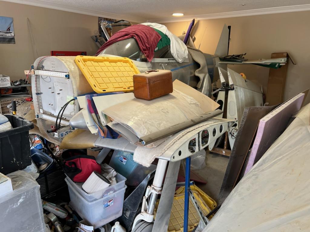
With all the work that he'd been doing on other projects, the Prowler got relegated to the back of the "pile" temporarily:
and:
In the interest of full disclosure, the Prowler project has also gotten put on the back burner because Bryan had been waiting for DeltaHawk to provide a diesel aircraft engine which Bryan had put a fairly large deposit on.  DeltaHawk never came through and Bryan eventually got his deposit back.

Now, the Prowler has a new home of it's own in the "hangar bay":
and:
On the right side of the hangar bay is the new workshop:
And, here is the soon-to-be man-cave above the hangar bay and workshop:
Nice work, Bryan.  It looks awesome.  I hope I'm not the only one feeling a little envious of your new "digs."  I'm sure it's going to a great place to finish up your Prowler.  Thanks for sharing!

Well, that's it for this update.   I have a bit more Prowler work in the works right now.  I'll report on that soon.  Thanks for stopping by to check out the update.