I made a few parts for Vaughn and his Prowler lately. So, in an effort to make good on my resolution on do more blog updates more frequently, I am just gonna do it.
In This Update:
A. Radiator Fairings;
B. Engine Compartment Longerons;
C. An Update From Bryan
Before I move onto the update, I had a couple of pics to share from the "day job." For those of you that do not get around Oshkosh, WI, except for during AirVenture - here's a look at what the place looks like in January:

I also got a neat picture of a moon rise recently. It's near full moon and what makes this picture neat is that it's taken just after sunset (behind the photo). If you've never had an opportunity to experience a sunset from higher altitudes, the darker strip along the eastern horizon is where the sun is no longer illuminating the sky. The yellowish band (and above) is where the sun is still illuminating the sky. Here, there is a mostly smooth undercast layer below the horizon. So, the sun has just set and the moon is just rising - which means that they are essentially 180 degrees apart when this picture was taken:

A. Radiator Fairings - As the title of the update implies, Vaughn only got one set of radiator fairings for his Prowler and needed another. So, I fabricated a set of those for him. The first step in the process of making the radiator wall fairings was to locate the pattern and the forming blocks (aka forming dies). Here is the pattern, and I have traced and cut out two matching blanks to be formed:


Again, the metal has to be "shrunk" [or "shrinked", or placed in a shrinker"??] in order to get the wavies out of the edge of the flange. That is done using a shrinker. It doesn't take a lot, and more small shrinks is better than a few large ones, if you want to end up with the best finish. Once I shrink the flange a little, I put it back into the former and where the flange fits tight with the form block, I put an X on the flange with a Sharpie marker where it does not need any more shrinking. I put an O where it still needs a little more. Once the flange fits snugly around the entire radius, the forming on that flange is done:

Inside radius bends are pretty much done the opposite way - and you don't really even need to take the part out of the form blocks. In forming an inside radius, the flange will naturally want to stretch on the outside edge. So, I start hammering at the ends and try to move the metal towards the middle as much as possible. This reduces the thinning of the outside edge of the flange material.
Here, again, taking more small hammer strokes instead of fewer larger strokes will yield better results. The flange will come out smoother and you'll be less likely to split the outside edge of the flange while working the material. Here is the inside radius flange, about 1/2 formed:


B. Engine Compartment Longerons - Vaughn is also going to get started laying out his FWF package and wanted to get the parts together to start framing in his engine compartment. He is going to be installing a PowerSport package on his Prowler. This is based on a Mazda rotary engine. This engine will be lighter than the George Morse package, so he is going to have to move things forward a bit to get the W&B and CG to work into the range of the 6 (almost 7) airplanes that have been certified.
In order help Vaughn with that, I made him a forward engine compartment bulkhead (horse collar) that I covered in a previous update. Now, I have fabricated the longerons to connect between the firewall and the horse collar. Here's how that went.
There are 6 longerons that make up the engine compartment. There are two on top, two on the sides and two lower ones. They are kinda important from the standpoint that these longerons set the basis for the shape of the front of the Prowler (what the silhouette of the airplane looks like from the top down and from each side). So, I kinda want to get that right!
The first step to making these longerons is, again, finding the material and finding the pattern. The pattern that I use is one that I made from Ray's engine compartment longerons. All I did was tape some paper grocery bags together, lay his longerons down (on edge) onto the paper, and then traced them out. I was trying to get the proper curvature of each set.
The longerons are made from 2024-T3 aluminum that is cut into 8 ft strips and then I form them into a C or U shaped channel with 3/4" flanges. A few years back, I was working on forming some of the aileron and flap hinge supports on the rear spar of outboard wings and while doing that, I also made several extra of these C channels. I found them and cut them into the correct lengths for each of the 3 sets of engine compartment longerons. Here is the pattern taped to the work bench and the pieces that I used to form the longerons:

I started with the top longeron set. I started by placing the straight channel on the pattern and then marking the 1st place where it needed shrinking on the fwd end. After the 1st shrink, I set the longeron on the tracking and mark where the next place that needs shrinking. Here is the first top longeron after several iterations of this:


This leads to the second tricky part, trying to stretch a flange that has had too much shrinking. I made the same mistake that I have made once before with these longerons. I tried to use the strecther device to take out some of the shrink in one of the flange. Well, it does not work. As you shrink the flanges, you work harden the 2024-T3 even more. So, when you try to stretch it, even just a little, SNAP! It breaks the flange. Here is the longeron with the broken flange after I drill-stopped the crack and cleaned it up a little:


So to prevent breaking any more of the longerons, what I decided to try, instead of using a stretcher device, was to hammer the flanges. I put a radius on the square end of my anvil, and then clamped it to the welding table. Here is what that looked like:


Moving along, here are the two side longerons completed:


With Vaughn's longerons completed, I just had to figure out how to ship them to him. I wanted something sturdy, that would protect them and keep them from getting crushed. I finally decided that an 8" diameter cement form from Home Depot would work the best. Here are the longerons and the radiator fairings ready to ship:

C. An Update From Bryan - So, Bryan retired about 3-1/2 years ago. After that, he started working on several projects around the house, including: a new back yard with large retaining wall, an new deck, and a new, detached garage/man-cave to use while completing his Prowler. Of course, CoVid slowed the progress to a slow crawl at times, not to mention the battles with the local building department. But, just recently, Bryan sent me some pics and announced that he had gotten the go-ahead from the building department to move into some of the new garage. It's actually an RV garage, a hangar, and a workshop combined - with a man-cave above the hangar. Here's the front view (house is on the right and new garage on the left at the end of the drive):

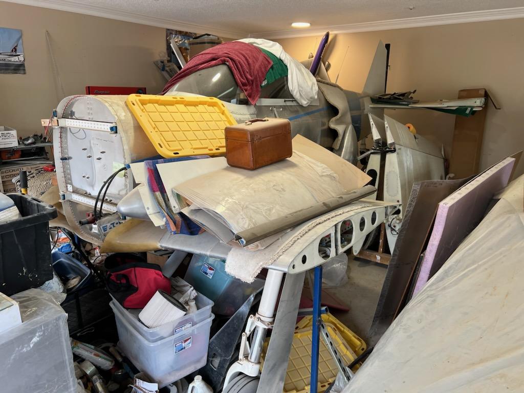

Now, the Prowler has a new home of it's own in the "hangar bay":


Well, that's it for this update. I have a bit more Prowler work in the works right now. I'll report on that soon. Thanks for stopping by to check out the update.


No comments:
Post a Comment