Happy New Year Everyone!
I hope you all had a happy holiday season. The "Bomb Cyclone" made for a pretty cold and snowy holiday season this year over most of the country. If you were affected by this weather, I hope you were able to get through it safely. My favorite stat from that storm was the temp drop in Cheyenne,WY on the Wed before Christmas. The temp dropped 30 deg F in 10 minutes! The 30 min temp change was 39 deg F. That's more than 1 deg F per minute fall in temp. (
Check it out) Pretty crazy!!
We've been getting a bit of rain in the California North state area. In fact, I think we have already gotten more rain this Nov/Dec than we got in the whole winter last year. It's helping relieve the drought conditions a little (or will in the spring). It had been raining most of the week before I took off recently from the SFO airport headed to JFK and I snapped this pic of Lake Tahoe area:
Nice to see snow in the Sierras again!
As I mentioned in the last blog update, I am going to dedicate this update completely to bringing you all up to date on the progress that Francis has made on building their Prowler in France. My last update on the French Prowler included work up until March 2020. Since then Francis has been sending me a lot of awesome pics and messages on how he is doing building their Prowler. I want to share that all with you now. To keep a sort-of timeline, I'll break this update into approximately 6 month periods. I have one update that should have been included in a previous blog post covering Dec 2020. I'll post that and then jump up to continue with May-Dec to 2021. So, here's the itinerary:
A. Dec 2020 - Parts for Francis
B. May-Dec 2021 - Wing Work (Ailerons, Flaps & Radiators)
C. Jan-Jun 2022 - Wing Work (Outboard Wing Skins & Flap Actuator Work)
D. Jul-Nov 2022 - Completing Wing Work (Flap Actuators & Radiator Door Actuators)
E. Dec 2022 - Cockpit Floor & Cockpit Framing Prep Work
Here we go!
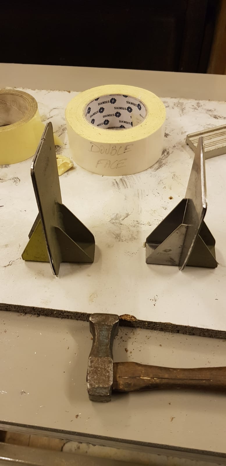
A. Dec 2020 - Parts For Francis - After finishing the dies (form blocks) for the stringers under the aft cockpit floor, I needed to make a set for Francis. I fixed a bad spot that had caused all the previous builders to do a lot of shimming to get skin to lay flat under the aft cockpit area. Since I knew that Francis hadn't gotten to this part of his build yet, I wanted to get a set of them made and sent out to him. I happened to have two of our daughters at home one weekend, so I cut out some blanks and had each one take a turn and do the pressing operation to form the two stringers for Francis. Here they are holding their finished products:
Then, I made a shipping box out of wood so that they would not get damaged on the trip to France. Here they are, ready for shipping:
A little while later, I also pulled a set of aft flap hinge support brackets from inventory (that I had made some time ago). Francis needed a set, so I put them in a sturdy triangular tube and put that together with the aft floor stringers and shipped them at the same time:
These were Francis' Christmas present from me last year! As you will see in the next sections of the blog update, Francis has already installed the flap hinge support brackets and is working on installing the floor stingers soon. Thanks for the help, Ladies!
B. May-Dec2021 - Wing Work (Ailerons, Flaps and Radiators) - My last update on the French Prowler showed the work Francis was doing on the center section of the aircraft wing. He was working on the framing and skins of that section. In the second half of 2021 the focus shifted to the trailing edges of the wings and the radiators. Here is the trailing edge of what looks like the left wing of their aircraft and some lay-out marks that Francis has done.
In the pic below, you can see one of the flap hinge support brackets that I mentioned shipping to Francis (above). This is a long, tapered channel with approx 45 deg flanges formed into it. This provides an angled support to the skin that comes off of the aft spar and allows a rigid place to attach 1/2 of the hinge that supports the flap segments. This is the right wing, and the top of this tapered support bracket (on the left side) attaches to the rear spar near the top. Then, it angles back to join the skin aft of the rear spar (that's the flange you see farthest to the right pointed up (aft):
This pic below is the same wing, taken from the wingtip looking in. You can just see the flange of the support bracket pointing up. The bottom skin is not on the wing yet, but when it does get put on, it will be attached on the aft edge to the flange coming off of the angled support bracket (with one hinge tab which is 1/2 of the hinge that will allow the flap attachment):
Francis found a bad spot on one of the radiators that came with his kit (I think that George used to pre-attach the aluminum blocks for the plumbing onto the radiators on his kits). Being an aircraft welder (by trade), the repair was an easy step for him:
Here are three more pics of work that Francis did while working on the flaps, and radiators.....one:
two:
three:
C. Jan-Jun2022 - Wing Work (Wing Skins & Flap Actuator Work) - With the flaps, ailerons and radiators installed on their airplane, the focus shifted to installing the actuating system for the radiator doors and beginning fabricating the wing skins in preparation for the finish installation. Here is the linear actuator that Francis has installed for moving the radiator door linkage:
Same thing from another angle where you can better see the limit switch that he incorporated to stop the travel at the max extension point:
More close up of the limit switch:
I am not certain what this pic below is showing, but it appears to be some kind of electrical connectors that I assume will power the linear actuators for the radiator doors and the flaps. Or, since this is at the wing junction (where the outer wing is attached to the center wing section) this might be part of his fuel level sensing system - as the forward tanks in the outer wings are close to this area when the outer wings are on the plane:
It looks like Francis in this pic has breadboarded some kind of control system for the radiator door system:
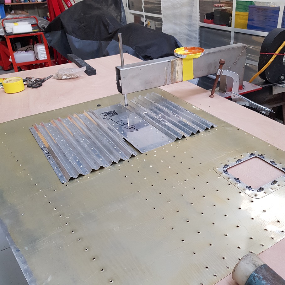
In conjunction with the radiator door actuator work, Francis was also fabricating the inboard and outboard wing skins. Here is the installation of the wing skin stiffener on the center wing section. The hole on the right is the access panel that Francis put into the skin that will allow access to the top of the torque box, in case of possible maintenance in the future:
Same panel, installed onto the top of the center wing section:
Looks awesome:
This is the setup that Francis made for dimpling the outboard wing skins:
Same thing, with the access panels and doublers added:
I believe this is the lower outboard wing skin where the pitot static tube will be installed:
One outboard lower wing skin ready to install:
Here was a tip that Francis passed on to me. He used this removable tape to hold the doubler in place while riveting:
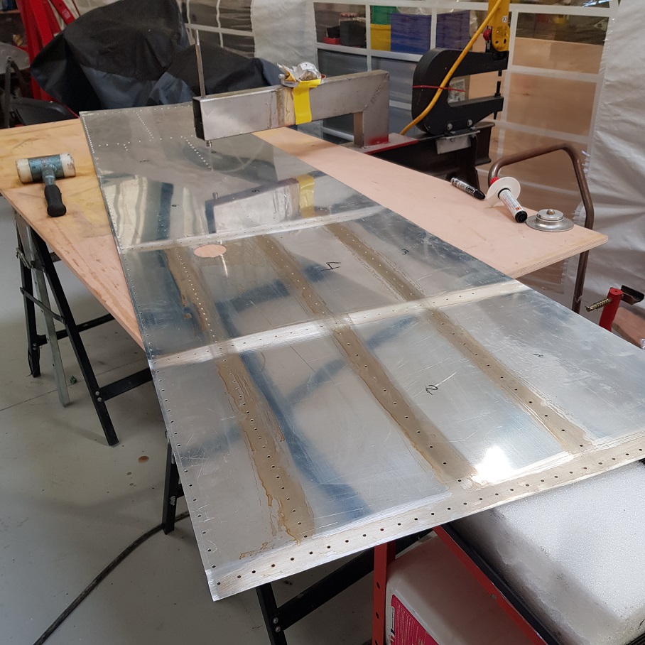
And; one mostly completed outboard wing:
Francis made a tube to submerge angle brackets into for alodine treatment and then clamped it upright in his vise. I think these are wing skin stiffeners:
Here are the treated angles:
D. Jul-Nov 2022 - Completing Wing Work (Flap Actuators & Radiator Door Actuators) - in the second half of this year, Francis continued on completing his center wing systems. This is either a revision to the actuator control for the radiator doors that was shown above, or it's a different controller used for the flap controller:
I'm not certain which it is for, but I'm assuming it is for the radiator door actuators. The reason I think that is because these pictures came at the same time that he finished the radiator installations. Here is the right wing radiator with the door installed:
Here's the same radiator looking outboard with the door open:
And same view with the door closed:
And, finally, video proof that both radiator doors work properly demonstrated in person by the star of the show.....Francis himself!!!!!
Nice job, Francis!! That's outstanding work.
Moving on to the flap actuator, I think this was an initial mock-up piece that Francis made to test the fit of this design to actuate the flap extension limit switch. It looks like he cut this piece from a square extruded aluminum tube and fashioned a tab that would impact the limit switch when the flaps were fully extended:
Here's that part attached to the flap actuation torque tube. Notice that Francis also incorporated Ray's design for the 3-piece flap actuator torque tube:
And, a side view:
Then, it looks like in this pic below, that he fabricated a new part from heavier aluminum to actuate the limit switch:
Nice work on that! It is a fairly simple, clean design!
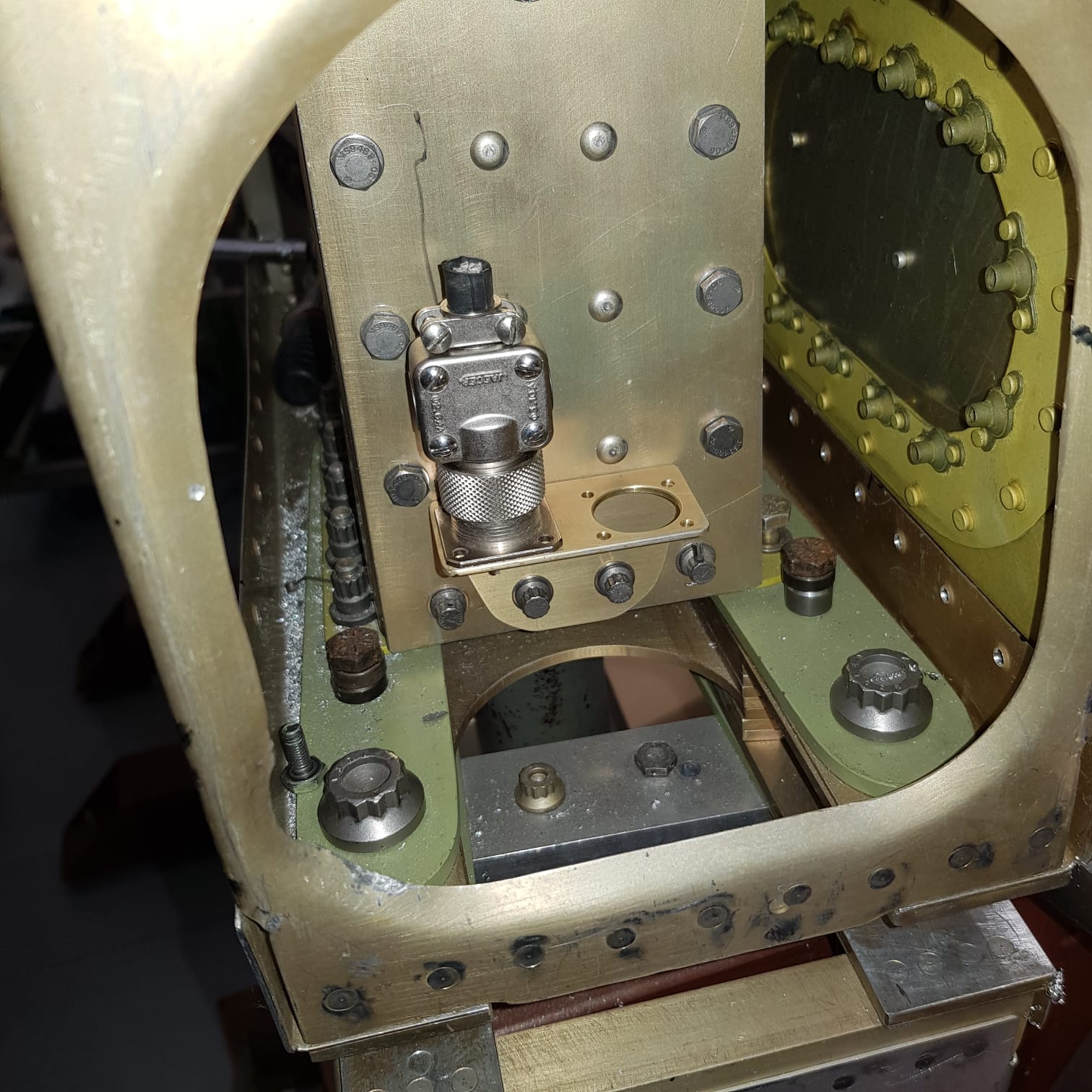
E. Dec 2022 - Cockpit Floor & Cockpit Framing Prep Work - Now, most recently, Francis has sent me the pictures below where it looks like he is beginning to frame up the cockpit floor. Even though he just sent me these pics, I think they were taken sometime earlier before he finished the radiator installations. The reason I say that is because in these pics, the lower skins (and doors) are not installed on the radiator boxes. In any event, remember those parts that the girls helped me make for Francis?? Well, here they are:
That's them, on top, attached to the rear spar. In the picture below, they are probably cleco'ed in place and have the cockpit floor clamped in place as well:
Another view:
Here is the cockpit floor from the top side. He even has the flight control sticks in place!! Looks great:
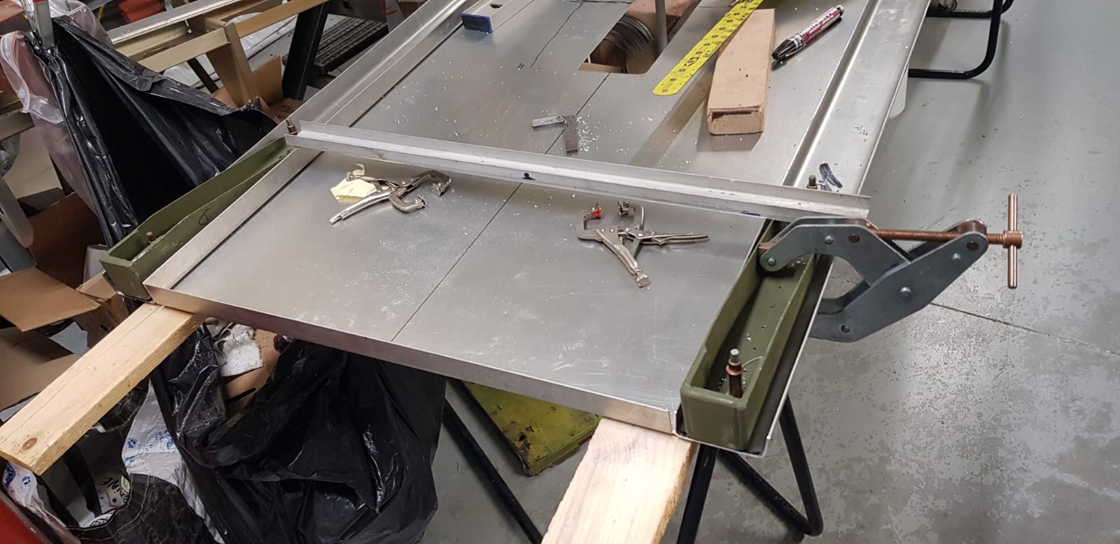
Here is the cockpit floor, back off of the wing jig and laying upright on a bench (or saw horses) so that he can begin the floor layout and fabrication:
Here is a footwell for the cockpit floor - with some of Francis' humor included on it:
And, here is the floor with a footwell and on of the side channels in place:
Another view:
Here Francis is laying out the steel to make another set of the gusset plates for the negative G mod for the wing spar. He had one set that came with the kit, but there is actually one set on the front of the fuselage former above the main spar, and another set that attaches to the aft side. Here he is copying the dimensions and laying out for cutting another set:
Here is the new set and the original set:
This next picture is Francis laying out the cockpit framing on the forward end of the cockpit floor. Here he has the left side steel engine mount bracket laying on the floor (mounted inside the forward end of the left floor channel) with another piece of aluminum clamped on to simulate the back side of the firewall:
Here are both engine mount brackets in place on the front end of the cockpit floor inside of the two floor channels with the upper floor attach angle between the two engine mount brackets:
Eventually, the firewall will be riveted to the upper and lower floor angle brackets and the engine mount brackets (that are on the forward side of the firewall) will be bolted to these steel brackets mounted in the floor channels. This transmits the tractor forces from the engine mount to the firewall and the floor channels and out to the skin all around the fuselage (aft of the firewall) - exactly where it should go!
I'm not certain what we are seeing in the next pic. It looks to me like it is the aluminum 90 deg angle brackets that came with the kit that will go on the top and bottom of both ends of the cockpit floor and attach the floor to the firewall in front, and the large fuselage former in the back. Looks like he found a crack that formed in one of the angles while bending it:
I think the pic below is of a previous builder's firewall, but it shows the hole patterns cut into it. The double row of holes about 1/4 the way up from the bottom will hold a 2" channel on the front side of the firewall and will also be used to hold the cockpit floor angles on the back side. This will help to stiffen the firewall and transfer some of the forces from the motor mount into the firewall and into the skins:
Here is Francis' firewall getting ready for the hole pattern layout:
The floor channels are used to (obviously) stiffen the cockpit floor, but they also help to transmit the tractor forces of the engine mount into the cockpit floor and to the skins that are riveted to it all down the side of the fuselage. These floor channels are parallel on opposite sides of the cockpit floor for about 2/3 of the length of the floor. Then, just about where the aft stick is mounted, the channels become angles and bend in slowly as you travel aft down the cockpit floor. Here is a 3D CAD drawing of this part to better show how the part goes from a 2 flange channel to a single flange angle bracket:

This is how the fuselage in a Prowler transitions from a mostly rectangular tube up front (from the firewall back to about where the aft stick is located) to more of a tapered cone shape of the aft fuselage at the empenage. This pic below is showing where the inside flange of the floor channel has been removed and the slots have been cut into the flange that will attach to the cockpit floor. These slots will allow the angle to bend slightly and conform to the shape of the aft cockpit floor. Here's what the slots look like:
Here are the forward ends of these floor channels clamped together. I think he is comparing the length and width of the channels here:
At the aft end of the cockpit floor, the upper and lower angle brackets get riveted to the large fuselage former:
Same fuselage former viewed from the front:
This fuselage former that is just aft of the cockpit floor is mounted in place and then the fuselage side longerons are added to frame in the cockpit. These longerons have to have the same contours formed into them that the aft ends of the floor side channels have. Then, when the side longerons are completed and attached to the aft fuselage former, the top of that large fuselage former is trimmed off even with the top of the cockpit side wall. Then, the sloped baggage compartment door frame is added from there. We will see that develop as Francis gets farther along in the near future.
Awesome progress, Francis!! I really, really appreciate you sharing pictures of your progress so that I can share it all with the other Prowler builders and enthusiasts!
OH!! I forgot to mention earlier, Francis has told me that he is now retired. Congratulations on your retirement, Francis!! I expect that I will be getting more and faster updates from him now! I will be happy to post that info here in the blog. He has also mentioned that he wants to come to AirVenture in 2023 to meet more Prowler builders. That would be great! I'll have more on this later - stay tuned!
Again, Happy New Year Everyone!! I am already getting started on a couple more blog updates to catch everyone up on a few more events that happened during "CoVid". I hope to get those posted over the next couple of weeks.


1 comment:
Outstanding!
Thanks for the update.
Post a Comment