Hello Again,
Thanks for stopping by to check on the progress here.
Well, after many tweaks, lots of calibration and then more testing - I've finally found success bending 2024-T3 with the press brake that we built last March. Now, with the ability to cut out parts with the MotionMaster router and then bend them with the press brake, I finally have the processes in place to make many of the airplane's parts. This includes any part that is cut from flat stock and then has any kind of straight flanges or bends required to complete the part.
This capability allows me to make all of the aluminum main spar parts (both center and outboard sections), and most of the steel main spar parts. Part of this update includes the set-up of my Ganesh CNC 3 Axis Mill that will allow me to make the 4130 steel parts that I need to build the main spar. Shortly, I will have the all of the spar parts I need to assemble the entire main spar and install it in the wing jig.
When I do get the main spar installed in the jig, my focus will shift to buying and/or building the machines to give me production capability for the airplane parts that I need to made using the rubber-hydroforming process that I've mentioned in previous posts. Of course, progress on the airplane will (necessarily) slow down a lot while I work on these rubber pressing projects. But, once complete, I will have the ability to press out my wing ribs, install them onto the wing spar, and continue to build the wing structure.
The capability to press these parts will also mark the time when I have production capability for most of the airplane - the only notable exception being the majority of the landing gear parts. Historically, the landing gear gets installed after the wing is completed in the jig. The center section gets removed from the jig, flipped upside-down on the cockpit floor and then the landing gear is installed onto the torque box torque tubes. Since I have a while yet before the wing is complete, there is time to to contemplate the production of landing gear parts.
OK, that's the very short term, short term, and medium-term future plan/goals here. But, now, let me catch you up on what I've been up to in the past 3-4 weeks. In this update:
Press Brake Back-Gauge Completion
Press Brake Calibration
Outboard Wing Spar Channels
Center & Outboard Skin Flanges and Bridge Shims
Wing Rib Attach Angles
Ganesh GMV-2 CNC 3 Axis Knee Mill Set-up
Builder Updates
Ray,Chuck & Bud
Bryan
Roy - Kit 13 For Sale
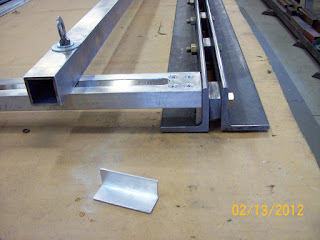
Press Brake Back-Gauge Completion - The flanges on most parts are uniform in width, so I wanted to have a convenient way to set the width of the flange for pressing. I came up with this system that allows me to quickly set the flange width. This pic shows the set-up out of the press:
With the distances involved, I had to add a "spacer" to be able to get the scales placed in an acceptable area. So, I riveted an aluminum angle to the back side of the back-gauge. Once installed in the press, and after a few test bends, I was able to accurately calibrate the counter-sunk scales.
Here's a overview of the whole assembly out of the press:
Press Brake Calibration - In a previous post, I outlined the beginning of the press brake calibration and bending of test strips. During that time I found that I could not just bend clips at each end of the lower die beam, but to get more accurate results I also had to have a piece in the center of the die. So, I started bending sets of 3 pieces and trying various plunge depths. As I did this, I noticed a few things that were affecting the consistency of the bend angles. First, I determined that using the hydraulic system (that I outlined in a previous post) was causing variability because it was essentially "overkill." The hydraulic rams were pushing on the stop blocks too much and flexing the entire press brake - producing inconsistencies.

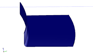
The second thing I noticed was that I was getting some strange warping of the parts that I was bending. I wasn't sure if that was because of the press brake, or the material. I suspected that is was the material causing this warping, because it was SO uniform. I figured that the press brake couldn't be doing this so perfectly uniformly. Here's a CAD drawing that simulates the warping that I was seeing:
In an effort to figure this out, I found a website called
www.homebuiltairplanes.com that has a sheet metal forum for questions. I posted on this site and eventually got some great feedback that did help explain what what happening. Turns out that this warping is called "cambering" and
IT IS a function of the material. As the material gets stretched and compressed along the bend line, it causes this warping to happen. You can
check out this link to the thread for more info.
Armed with this knowledge, I found a way to deal with this deformation and was finally ready to try some long pieces in the brake. I decided to start on some 2" ID channels, since there are many of these in the airplane and if I messed them up too bad, I wouldn't be wasting too much money. By the time I completed the third channel the bends were coming out pretty nice. Here's a pic of the first two channels lying on the mat and looking down the edge of the 3rd channel :
By the time I'd gotten the third channel bent up satisfactorily, I got brave enough to try one of the outboard wing spar channels. That's next.
Outboard Wing Spar Channels - Here's the first spar channel in the press:
Here you can see the finished product - fresh from the press brake and with the long spar cap strips installed onto the channels. They came out great.
This was a big turning point for me in the quest to re-establish some limited production for Prowler Aviation. It gave me a lot of satisfaction and motivation. A lot of what I've been working on for many years now is represented in these two parts. I've actually been working on a satisfactory way to bend these long pieces for over 3 years - starting with the unsuccessful attempts to repair and modify the 8 foot sheet metal leaf brake.
So, completion of these outboard wing spar channels was REALLY noteworthy because:
1. They were cut from G-code that came from the CAD drawings that I've been working on for over 2 years;
2. They were cut in the MotionMonster CNC router that I'd spent much of last year repairing, modifying and installing in the shop. And;
3. The were bent in the one-of-a-kind, purpose built press brake that my dad and I designed and built while he was visiting last March.
This was a pretty sweet success!
Center & Outboard Skin Flanges, and Bridge Shims - Energized by the success with the spar channels, I moved on to the wing spar skin flanges. Here are the forward skin flanges for the center section.
Here are the aft skin flanges for the center section of the main wing spar:
The next parts on the "To Do" list were the spacers that fit between the upper and lower spar cap strips under the wing rib flanges (both on the center section and the outboard sections). Here is a shot of one set of these spacers in the mill getting machined down to size:
Here's the entire set of the spacers:
Wing Rib Attach Angles - The last of the aluminum parts that I needed to fabricate were the angle clips used to mount the wing ribs to the main spar. Since I don't have a sheet metal shear (yet), I used the MotionMonster to cut some 1-3/4" strips from a 4' piece of 0.050" aluminum (on the right in the picture below). The parts in the middle (below) are specially shaped rib attach angles that go on the inboard rib of the outboard wing section. The piece on the left is for the wing pylon attach points (that is actually left-over stock from George, so I didn't need to fabricate that piece).
Once I got the stock cut into strips, it was time to cut the strips to the correct lengths:
Then, bending in the press brake was next:
Here's the completed parts after bending in the press brake.
The bends are coming out very nice - correct angle (90 deg) and uniform over the length of the angle:
Ganesh GMV-2 CNC 3 Axis Knee Mill Set-up - So, with all of the aluminum parts of the spar complete, the only parts left to make for the spar are steel parts. These parts are made from 4130 chromoly steel. Because the forces involved in cutting the steel go up, they require a bit more fixturing to hold them while cutting. The vacuum table on the router isn't capable of holding the material for these parts - so it is time to get the CNC mill running. The first task was to find a place to put it in the shop. The shop is starting to get full. But, I decided to take a day and move the mill into a position near the Bridgeport manual mill - since I have the 3phase power there, a lot of the tooling there, and it's closer to the workbench (I can't tell you how many 60 foot round trips I made to the workbench while setting up the MotionMonster!) So here's a pic taken just after rolling the CNC mill into position with 3/4" pipe.

Next was getting power set up to the machine. Here's a switch box that I wired up to turn on power to part of the machine:
Here is a picture of the machine in it's new home spot in the shop:
This is a close up view of the controller on the CNC mill. It is (coincidentally) made by the same company that made the controller for the MotionMonster - only a few generations newer. The router has the Fagor 8025M controller and the CNC mill has the Fagor 8040M controller. This is a much more capable controller, but it is also going to take a bit longer to learn how to use - it seems. Here's an older file photo:
Once I got the machine powered up again, I went to work getting it hooked up to a laptop computer. After a little messing around, I got the machine to sync with the laptop software and got the following screen shots:
Here's what the software looks like on the laptop. This is the WinDNC software provided by Fagor. It actually does a pretty good job working with the mill controller. It even has a remote keyboard function that allows me to control the machine from a the workbench across the shop. That's cool!
Here's the first job that I'm going to tackle with the mill:
This is the wing spar attachment plates and the fixture plate that I made up to hold these parts during machining. This is a left over piece of inventory that I got from George. Turns out, I modified the hole pattern on this part just a little bit during the CAD process. I did this because, as it currently exists on this part, the hole pattern was not quite symmetric or uniform. I made it symmetric and uniform, so that now these plates can be used universally on any of the 4 spots on the airplane - AND the holes line up perfectly with all of the wing spar cap strips, skin flanges, etc.
Builder Updates -
Ray, Chuck & Bud - It's been a while, so I checked in with Ray recently. Ray is recovering from some neck surgery, but should be getting more done with his engine work soon. In the meantime, he's been working on paperwork, checklist, and other "lite duty" tasks associated with building the airplane. He reports that Chuck is continuing to have fun flying his Prowler. Apparently, his airplane (even without the supercharger) will do high speed passes at the airport that might have been just a tad over the speed limit. Of course, this is all rumor and third party info - so take it FWIW. Also, rumor has it that Bud is close to running his engine again. I hope to have better updates from them all next time.
Bryan - Meanwhile, Bryan sent a few pictures with some questions/discussion about tailwheel doors. He's finalizing the design of his TW doors and operating gear. I'll report more on this in a future post - but here's a couple of pix of what he is thinking about:
Roy's Kit #13 is still FOR SALE - Roy is still looking for a good home for his Kit #13. Here are a few pix:
If you are interested, please contact me via the
website feedback link and I will pass along contact info. If you know anyone interested in a kit, please provide them with this info. Thanks.
Well, that does it for this update. I hope this was informative and maybe even entertaining. Thanks for stopping by. I'll post an update again in early April.






.JPG)


