Wednesday, December 8, 2010

Prowler Year End Wrap-up

Hello Again,
Thanks for stopping by to check in on us here at the new Prowler Aviation. There has been a fair amount of news since our last post, so lets get started. In this post:

1. CAD Work Continues
2. New FWF Mock-up Update
3. Builder Updates
3A. Ray Seim (Kit #10)
3B. Nicolas Hombruex (Kit #11)
3C. Chuck Westcott (Kit #12)
3D. Bud Tedesco (Kit #16)
3E. John "Cabi" Cabigas (Kit #17)
4. George Is Back On His Feet
5. Looking Ahead


1. CAD Work Continues - We're back on the CAD horse again here. We just finished CADing out the Main Landing Gear. Here's a pic of the 3D composite drawing. Keep in mind that for each separate colored piece you see here, there is a full technical drawing with a 3D representation of that part stored in another file. This picture is a collection of all the the 3D part representations all gathered together in one place, with all parts then placed in the correct orientation relative to each other.
This main landing gear is going to be, hands down, the most complex and expensive part of the Prowler Kit. The retractable landing gear adds a huge level of complexity when compared to most kits out on the market (both in pieces to produce and systems to make it operate). This is where the new Prowler Kits will be "make or break." By this I mean, if we can find an efficient, practical and cost effective way to make these parts - the kit might still be affordable enough to make a go of it. That's where all this CAD and CNC stuff comes into play. If we can make production computer controlled, make it repeatable, and make it (fairly) simple - it just might be a successful endeavor. Time will tell.


2. New FWF Mock-up Update - We've completed a little more on the new FWF mock-up introduced in the last blog update. The most notable new portion of the FWF mock-up is that the engine has been moved back 2 inches and a 2 inch prop extension was added. This was necessary to gain clearance room in the lower forward area of the new PSRU. Geared Drives has confirmed that this extension is acceptable. Also, the stand to hold the engine in place has been completely re-designed. By making the stand more narrow, it is now able to hold the engine in the correct location and still allow the engine cowling longerons to be placed where needed in order to finish the mock-up later. Also new is the change in the upward sweep of the lower longerons (and eventually the skins) to more closely replicate the original Prowler look. Here are few updated pix of the FWF mock-up:Also new since the last post are the upper and lower longerons themselves. I am still waiting to fabricate the side longerons until I can better define what the new exhaust system will entail. There are some issues to sort out relative to the type of exhaust system, the location of the exhaust system, etc. I don't want to spend time and effort to fabricate something only to have to tear it off and start over again (when I figure out,or stumble across, a better design for the exhaust). So this part will remain open for now.
BTW - the exhaust pipes you see in these pics are the ones that George used to test run his engines after assembly. They are much longer and more steeply pitched down than what was used on the current kits. I just put these on to help give some reference, and to use as a basis to start from in considering the new exhaust system.
We are also just beginning our initial discussions with Geared Drives on developing this as a FWF package for them. So far Bud and his crew have been very positive about the Prowler. More to follow.

3. Builder Updates - I have several builder updates to share this time. Some I have new pix to share, some I only have the information - but the news is generally very good and great progress is being made on many fronts. Here ya go (in Kit # order):
3A. Ray Seim (Kit #10) - In early Sep this year, I was able to help Ray mount his engine on this airplane for the first time. By late Sep he had completed some of the initial, basic plumbing hook-ups. Here's a shot: By late Oct, Ray had completed fitting his entire engine compartment and was ready to pull the airplane off the fuselage jig. Here's a pic of Ray and I working on removing the airplane from the jig: And here is a pic of his airplane sitting on it's own gear for the very first time: Here is almost the same shot a few days later with the mostly completed engine compartment installed: Ray does outstanding work! The airplane is currently in Van Nuys, CA having the fairings put on by an expert sheet metal guy. Ray decided to pay to have this part of the airplane completed for him, instead of trying to learn the art of this type of compound bending and working of sheet aluminum. Here's a pic of his templates and fairing lines on the airplane before shipping to Will's shop: It will, no doubt, look awesome when it is done.


3B. Nicolas Hombruex (Kit #11) - The Prowler Kit is now certified in France! Nicolas sent an email recently telling us that the French government has approved him to build the Prowler kit. In his own words:

Hello my friends. Here is my good news. I get a good
email: (11/26/2010):

Suite à discussion avec Mr Hombreux pour répondre à
mes interrogations, la DGAC émet un avis favorable à
l'éligibilité au CNRA du Kit US du Prowler qui peut -être
considéré comme lot matière.

Jean-Marie KLINKA
Project Certification Manager
DGAC/DSAC/NO/NAV

So now the Prowler aviation Jaguar's "kit" is allowed in
France!!!!!!

That's great news! Nice job Nicolas. Here are a few pix of some of Nicolas's kit shortly after he received the shipment that was arranged by John "Cabi" Cabigas.Nicolas tells me that he can now start working on his kit with the knowledge that it will be accepted in France and given an aircraft certificate. We look forward to supporting your efforts Nicolas. Congratulations!


3C. Chuck Westcott (Kit #12) - Chuck called a few weeks ago and reported a very successful follow on test flight for his Prowler. He reported that the airplane flew very well, all systems were working well, and the engine was running great. That is GREAT news after the troubles that Chuck has gone through recently with his plane.
He commissioned a very knowledgeable gent from the area to help him overhaul his engine after he started having serious engine trouble approx 18 months ago. They tore the engine down and started over essentially from scratch. The short story is the airplane now has a completely rebuilt LS1 engine with an improved PSRU (new bearings). The most notable improvement was the ignition system. After much research, they determined that George's original ignition system was not very robust and has the potential to ground itself out under some situations. Chuck's engine guy figured out a workable solution and I have distributed that information to all kit owners via our prowler builder's yahoo group. It has apparently made a significant difference in how well the engine now runs. Here's a file pic of the engine work in progress:
Chuck is now going to have Keith finish flying off the 40 hours for the experimental certificate. Good Stuff. Thanks for sharing the helpful information Chuck. Congratulations on a large step forward on your airplane.


3D. Bud Tedesco (Kit #16) - Well, Bud has the most incredible Prowler story so far. About a month ago I got an email from Bud explaining that while on test flight #4 the canopy departed the aircraft at approx. 5,500 ft and about 200mph! Nope, no joke! But that's not the amazing part. When he got the airplane back to base, he called and informed the Sheriff's office in two counties (BTW - he reports that the airplane flies very nicely "sans canopy"). Later that day, one of the Sheriff's offices called and told him that a farmer had found the canopy in a field! But wait - the story gets even better. When he picked up the canopy it APPEARED ALMOST COMPLETELY UNDAMAGED!!!! Turns out that the canopy apparently landed inverted and down on the forward end. This caused the canopy frame to be sprung outward in the forward portion. Using some undisclosed magic, Bud was able to "massage" the canopy back into shape and it is being re-installed on the airplane. Amazing!
Bud has the only Prowler, to date, that has a sliding canopy. The cause was determined to be the latching mechanism on the aft of the canopy. The forward part of the canopy is held by a flange mounted on top of the windscreen frame. The front of the canopy slides into/under this flange in the front and then the aft part of the canopy drops down and is held in place by pins into pillow blocks mounted to the canopy frame. There is a detent used to hold the aft latches in place when closed, but it had apparently vibrated out of the detent allowing the aft to pop loose. The canopy then only had to slide aft a short distance and it departed the plane. The only other damage was a short slice in the fuselage skin in the baggage compartment area on the right side of the aircraft.
Here is a file pic of Bud's airplane shortly after he moved it out of his basement and into it's new hangar this spring (the date on this pic is not correct - it is probably more like Apr/May of 2010).
That is an AMAZING story Bud. Awesome job on getting the aircraft, pilot and pieces all back down and back together safely!


3E. John "Cabi" Cabigas (Kit #17) - Cabi recently sent me some pix and a movie showing his plasma cutting system making his main wing spar cap strips. Here's a sample:
Cabi reports that the plasma works well on the .160" 2024-T3 material for the spars. That's good news. I have only tried 0.040" 2024-T3 so far (while cutting blanks for the FWF mock-up longerons), but I've been very pleased with the results. Good news for future Prowler Production. NICE JOB Cabi and thanks for sharing. Now get retired already so you can really get after that Prowler that is lurking in your garage and hangar!


4. George Is Back On His Feet - I am very happy to report that George is recovering very well from his broken femur surgery. In fact, I went to help him drag the airplane out of it's new home at the Red Bluff, CA (RBL) hangar a few days ago. The airplane hadn't been run in a while and it was a nice day - so we got it out at fired it up to circulate some fluids around in the motor. Before he fell recently, George had completed the annual on the airplane and got it back to airworthy condition. There have been a few lookers, but the airplane is still currently "For Sale." Here's a file pic from last year's Redding (RDD) airshow:


5. Looking Ahead - As 2010 becomes history, we're trying to set some loose "goals" for the new Prowler Aviation in 2011. Here's what stands out so far:

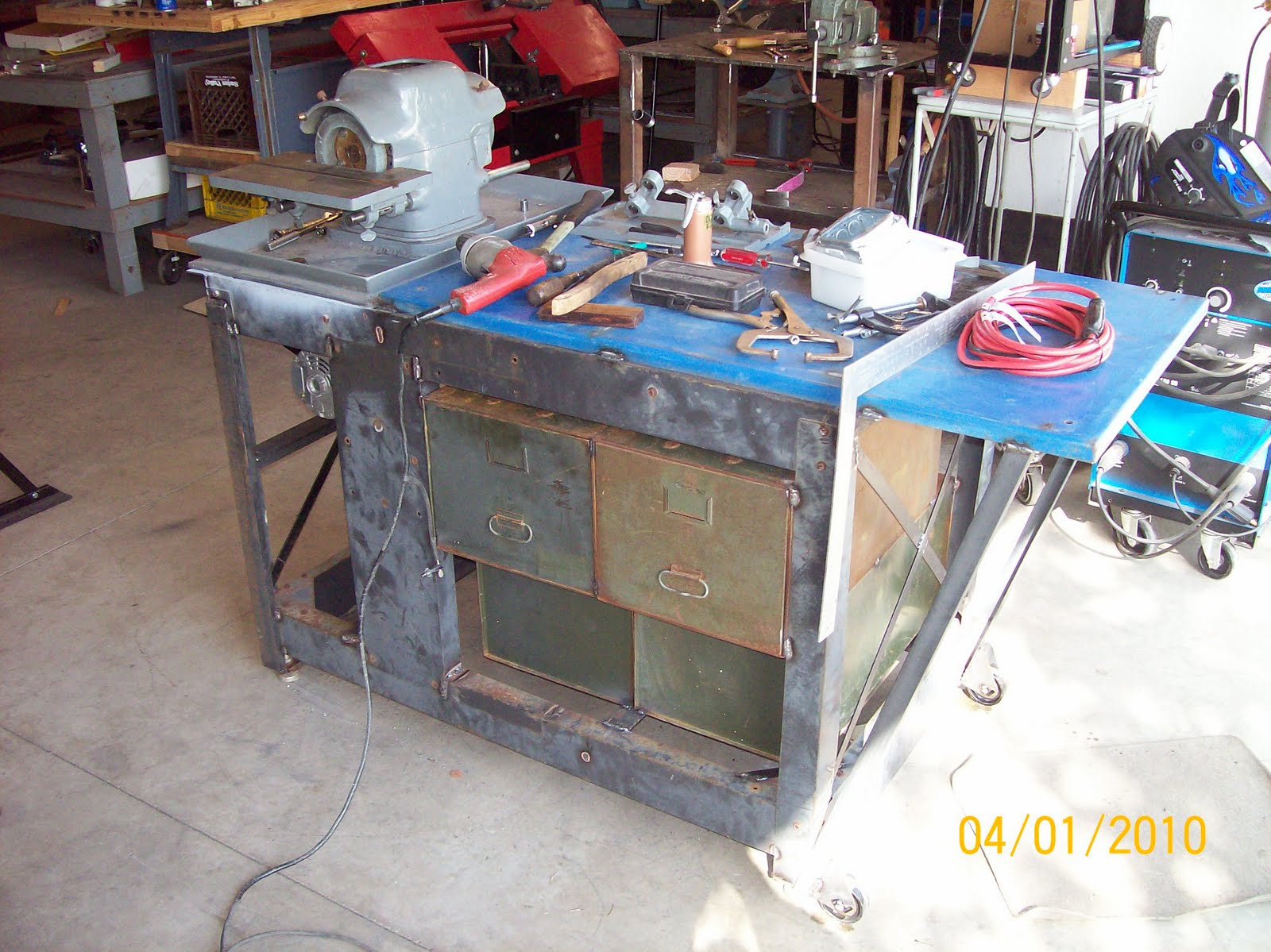
First- GET THE MAIN WING IN THE JIG. We've got to get set up with a sheet metal brake that works. The 8' sheet metal brake project from earlier this year has not paned out so far. Initial attempts to bend anything heavier than flashing material have resulted in poor bends. The brake isn't currently rigid enough to handle bending 0.040" 2024-T3. I'm surprised how tough and starchy this material really is. I think that it actually bends harder than mild steel. Here's a pic of the brake when we were working on it earlier this year. We'll try one more time to add some plate and beef it up, but if it doesn't improve it will end up out the door and we'll purchase a good machine:
Once we get a good working sheet metal brake, we can bend up the outboard wing spar channels and proceed to mount the center and outboard wing spar components into the jig. That will eventually (probably in 2012) give way to producing the wing ribs to place onto the spars.

Second - Continue working on the FWF mock up. Next step is to design and build the motor mounts that will be used with the Geared Drives PSRU and then put those on the mock-up to see how they fit. Then finish researching the exhaust system and complete the cowlings.

Third - Continue to complete the CAD work for all of the parts of the Kit that will be produced by Prowler. This work also lends itself to future assembly manual work - as these 3D representations will make valuable pictures to help describe the "how to" of kit assembly. With the CAD work completed we will also be able to begin learning the CAM techniques to take these drawings and start using the CNC mill to make some landing gear parts.

That's all for this update. Thanks for stopping by to see our progress.
We wish all of you a health and happy holiday season.
And, we look forward to seeing you all back again in 2011.

Friday, October 8, 2010

CAD Burnout - But Progress Continues!

Welcome Back! Thanks for checking in on us.

Well, after working on CAD drawings of Prowler parts for what seems like every spare minute of my life during the past year - I've officially reached burn out. But, that doesn't mean that progress towards production is halted. It just means we needed to strike out in a different direction for a while and do something a little creative - to keep the motivation level high.

In this update:
1. OK, Still Doing some CAD work
2. CNC Plasma Fixes
3. Ray's Prowler is Getting Its FWF
4. The New Prowler FWF Solution & Mock-up
5. Builder Progress Reports
6. Future Home of Prowler - East
7. Update on George

Here goes:

1. OK, Still Doing some CAD work - While CAD burn-out is evident, it has almost become a way of life, so the Prowler Part count-down does continue. The Flap Sub-kit is now complete and the Main Landing Gear is about to start. In addition, I have also had the opportunity to CAD up several parts to use in fabricating the new Prowler engine setup. See the next item for more of this. There have also been several CAD jobs for various parts that have come up in association with builder requests. So, we are staying CAD "proficient" thru the doldrums.

2. CNC Plasma Fixes - We found that while cutting round parts with the Prowler Plasma machine, perfect circles were coming out with two flat sides. Investigating the cause of this lead to some side-tracks and an eventual solution. Turns out, the flat sides were happening where the X axis was changing directions during a cut. Checking into the mechanical aspect, it was found that the gear rack on the X axis had dropped down and there was too much backlash in the gears. While fixing that, I found out that one of the studs that held the gear rack had broken off in the frame and was just rolling over when trying to tighten it. So, off with the gear rack and out with the MIG welder. Problem solved, until the gear rack bumped the gantry and the actual gear track section (all 4 feet) popped right off the rack. So, that lead to researching how and why this gear track was bonded to the rest of the rack. After, finally, finding the special Loctite product used to bond this track to the rack, it was fixed (actually re-bonded all 8 feet just for piece of mind). Here are a couple of pix of the re-bonding:
With the gear rack re-installed the problem was still there. Circles were still coming out with the two flat sides. So, assuming all the mechanical possibilities were covered, the problem had to be in the electronics. While testing one time, I noticed the table visibly shaking while simply running the X axis in a (presumed) continuous, constant speed move to the right and/or left. We ran some more tests and figured out that the X axis (stepper motor) was missing steps badly. After swapping motors, driver cards, and inputs we eventually logically deduced that the X axis motor driver PC card was at fault. After a bunch of research (again) we ordered and installed a new card:Problem solved! Since then, we have cut several parts with no problems. Here are some pix of parts cut out for another item in this post (FWF Mock-up) discussed below.

The plasma cutting table seems to be getting much more reliable and/or the operator is getting better. In any event, it definitely makes fabricating specialty parts a breeze.

3. Ray's Prowler is Getting Its FWF - Ray is making really good progress on his Prowler lately. During the past month I've visited him several times and even got to help him hang is motor during one visit. Check it out: The next visit, Ray had added several of the various plumbing lines and other connections: Since then, Ray has added several of the engine compartment framing pieces and the spinner attachment parts:Ray plans to have the engine cowlings on and fitted by the end of Oct. Then the plane will be trailered up to his sheetmetal guy to fabricate and fit all of the complex and compound skin parts (wing root fairings, etc.) Nice work Ray! Thanks for letting us be involved with your progress. The Plane is looking GREAT!
4. The New Prowler FWF Solution & Mock-up - All this work with Ray on his FWF, combined with the CAD burn-out, got me thinking about the new Prowler's FWF system. We have decided that the new Prowler Aviation is not going to be in the engine building business. At least, not initially. Getting the airframe finished will be challenge enough. George's engine system, while appealing, is just not practical. It requires a massive amount of mill, lathe and "gear-head" work to get one working FWF system. With Ray constantly telling me that "You need to get the build time down!," it is very apparent that the old way isn't going to work.
So, here is the FWF plan for the New Prowler: Order a stock crate LS1 engine with computer harness, add one Geared Drives PSRU system, top it off with a (yet to be determined) propeller and hub combination and go fly. (At least in theory.) We have been watching Bud Warren and his Geared Drive system for years and we're convinced that it is the best overall solution for the Prowler FWF - if it will fit! If it does, you just might see the Prowler listed with the rest of Geared Drives FWF packages. Check out their website at the link above.
So, will it fit? There-in lies the catch. The only way I know of to prove it is to mock-it-up and see if the original Prowler engine compartment components will fit around this new system. If not, it will make it easy to see what changes will be necessary to make it fit. I also thought that it would be a good time to tackle this with Ray working on this part of his airplane. By sort-of paralleling what Ray is working on, I can benefit from him allowing me to help with airplane. I've already collected tons of data, measurements and part information. I even found out there are parts of this airplane that I didn't know existed - Humph! But with a little help from our friends, we'll get it all together.
OK - I don't know if there is a standardized way of doing a FWF mock-up, but here's what I've done:
A. Collected damaged, broken, and worn-out parts of an LS1 engine:
B. Build a cart (so you can move things around in a shop that is starting to get pretty full!) C. Put the engine parts together and put them on a stand that can be used to move the engine in six degrees of freedom as needed:


C. Research the Geared Drives system and make a mock-up of the PSRU. Thankfully, there is just enough information available on their website to be able to CAD up the necessary parts to build a full-scale mock-up.
D. Add very contrasting paint: E. Cut out, paint and and add flanges to a firewall: F. Put it all together: In the next week, I'll be adding as many other engine compartment components as possible. Cabi and I will be getting together to fabricate the "horse collar" that attaches to the motor mount and makes of the forward framing that the engine cowling skins attach to. I'll also be adding longerons and eventually skins - although that will require the purchase of, and learning how to use, an English Wheel. That might take a bit more time.
So far, what is evident is that the engine will sit at least 3 inches lower than it does in George's design. This is a result of the Geared Drives design has the prop output shaft centerline 3 inches higher than George's design above the crankshaft centerline. Since the engine in the Geared Drives design sits opposite to what it would in a car (George drove his PSRU from the front of the engine), the rear sump oil pan might get too tight. This could require a switch to a front sump oil pan, which would put it in the back of the airplane engine.
So, there it is. There will be more to follow, but initial indications are that this new FWF will fit in the old Prowler engine compartment, with some minor changes.

5. Other Builder Progress Reports - Here is a quick run-down of the recent info I have on current builders. Some of this info is third hand, but from reliable sources.
A. Chuck Westcott is still working on ignition issues. His engine man has been busy with some other projects, but work continues and he plans to have his Prowler flying again soon. He wants to get the 40 hrs flown off and then the plane will go up for sale.
B. Bud Tedesco - Still working on the gripe list from the first flight. Hope to hear about a follow-on flight soon.
C. Steve Rogers - Has flown his Prowler a few time this summer up in SEA area. He has most of his gripe list taken care of and the plane is working well.
D. Bryan Davies - The day job has stepped it up a notch or two, so he's been working a bit more. However, he's working on building the fuselage. He also, finally landed a deal with the Delta Hawk guys and has put his deposit on his new engine.

6. Future Home of Prowler - East - Dave has spent the majority of the past year moving out of the old homestead, moving it all up to the BNA area, moving into a rental across the runway from their future home/hangar, and now actually building the new homestead. Here's a couple of pix:

Yes, that's a grass strip in the background. Beautiful house on a great property Dave!

7. Update on George - Recently, George was working on his 1963 Starfire and took a fall. He fractured his hip and needed to have a pin put in. He has had the surgery and made it back home last Tues. We wish him a speedy recovery.


Monday, August 16, 2010

CAD Work Continues in a Busy Summer

Hello Everyone,

Thanks for stopping by to check up on us. Well, the busy summer schedule associated with the "day job" combined with summer family activities has kept me out of the shop for almost 8 weeks! Fortunately, for the time being, there is always CAD work to do. It gives me something to do while commuting, sitting on call, sitting in a hotel room and any other long periods of time I spend sitting.

Of course, the biggest news of late is covered in the previous post; The 6th Prowler to fly. I will update again after Bud's follow-on flights. Congrats again, Bud!

IN THIS UPDATE:
1. A New Addition to the Prowler Shop
2. Bryan & Todd visit Ray and his Prowler
3. AirVenture 2010
4. CAD Work Progress

1. A New Addition to the Prowler Shop - The newest news is something that I've been working on for a good part of the summer. I came across a gent that had a 3 axis CNC Knee Mill for sale in his garage about 10 miles from the Prowler - West shop. It had sustained some damage and was sitting on a pallet and hadn't run in several years. To make a long story short, I took a gamble, put in a low-ball offer and bought the mill. Turns out that all the damage was just superficial and visual, but did not affect the functioning of the mill in any way. The only 1/2 day that I've had in the shop since mid June was hooking up the mill and testing it last Friday. Here it is:
Happily, the mill works fine and will be invaluable in making Prowler landing gear parts (or any 3D parts) in the future. We weren't really ready to spend the $,$$$ for this right now, but I was able to get it at such a ridiculously low cost that I couldn't afford NOT to do it now. Another sizable learning curve to conquer! Tally Ho.

2. Bryan & Todd visit Ray and his Prowler - In July Bryan and I both had some time off on the same day in the LAX area. Ray was available that day, so we drove up to see him. Bryan and Ray were able meet in person and it was cool to watch two guys that are very knowledgeable about Prowlers converse and compare their building experiences. Here's a pix from the visit:
Ray's airplane is moving right along. The day we visited Ray, he was just beginning the process of pulling many of the systems out of the cockpit to make room for riveting on the skins on the sides of the cockpit. He should have that done by now and be in the process of re-installing all of the systems. With that complete he will soon be tackling the engine and related systems. Here's a current pic of his panel:
It was a great day and we all enjoyed the visit. Thanks for hosting on short notice Ray.

3. AirVenture 2010 - One word universally sums up AirVenture this year - WET! It rained nearly 3 times the average monthly July rainfall for Wisconsin in the week just before AirVenture. There were large sections of KOSH and the EAA grounds that were not usable and were sectioned off so that planes, trains, automobiles and people wouldn't get stuck in the mud. It made for a fairly disorganized show this year, but the show did go on. It's truly amazing what EAA managed to come up with for alternate plans (on several fronts) to keep the show going, despite the weather. Here's a pic of an impromptu Prowler meeting with (L to R) Todd, Rick and Bryan:
The two highlights of the show for me this year were seeing two beautifully restored airplanes that have never been at any airshow before. This first one is a VERY RARE Royal Navy Spitfire (Carrier Version)!! Yep, with folding wings and a tailhook! There are only 4 known to exist like it in the world, and this is the ONLY ONE that is flying in the entire world! The restoration on this airplane was the best that I have personally ever seen. This is an absolutely gorgeous warbird:
The other airplane was "Kathleen" a newly restored F4U Corsair. My personal favorite. If I could have any plane I wanted - the Corsair would be it! This one is owned by a former TWA guy who bought it from someone out of a jungle in El Salvador in the early 70's. It was restored by Airpower Unlimited in Jermoe, ID. It's a beautiful aircraft:
All things considered, it was a great time. Then again, the worst day at AirVenture still beats any other day of the year - period!!!

4. CAD Work Progress - I think I can safely say that I have about 2/3 of the Prowler parts CAD'ed out. Each part is actually drawn 4 ways: First - a standard 3-view of the part; Second - a flat pattern drawing of the part; Third - a plasma tool path drawing; and Fourth - a 3D view of the part. In addition, I then take the individual 3D part drawings and put them together into sub-assembly drawings (where appropriate). Here is an example of all of the Radiator parts gathered together into a 3D drawing (with one side off):
The colors are there for contrast to distinguish one part from the next. To date, here is the status of CAD work for the Prowler Sub-Kits:
Completed - Vert Stab, Horz Stab, Elevator, Rudder, Center Wing Section Main Spar, Outboard Wing Main Spar, Torque Boxes, Center & Outboard Rear Spar, Center Wing Components, Outboard Wing Components, Radiators, Ailerons, Flaps;
Remaining - Main Landing Gear, Fuselage - Cockpit, Fuselage - Aft, Tailwheel Components, Engine Compartment Components.

At this point, I am hoping to finish the majority of the CAD work by the end of the year. Once that is complete, we will start using the CAD info to begin making parts for our airplane. From this point on, when we make a part for our airplane, we will be doing it using the same processes that we will use in production later.

That's it for this update. Thanks for stopping by.


Tuesday, August 3, 2010

Another Prowler Completes 1st Flight!!!!

Congratulations to Bud Tedesco on completing his 1st flight! Bud reports that he and Prolwer N12BT took to the skies on 30Jul2010. Bud says the plane flies great and is very light and responsive on the controls.

Here is a video of Bud starting his Prowler before the first flight.


This is the video of his first flight. Right after the initial lift off you will see the airplane appear to sink back toward the runway. According to Bud that was intentional as he was going to set the airplane back onto the runway because of a "funny" engine sound. But the Prowler moves so fast that he realized that he was out of runway, so he again powered up and pulled back on the stick to continue the first flight. That sink apparently caused a few gasps back with the ground crew. He didn't really mean to scare anyone, and there wasn't anything really wrong with the plane.


Here are the YouTube links for these videos. You may find these have a little better quality:

http://www.youtube.com/watch?v=ZB1Ce1esYVc
http://www.youtube.com/watch?v=yJJrCm1tLec


Bud's gripe list from the first flight includes:
1. Oil pressure - seemed to be be fine before flight @ 65psi, but he noticed it was around 15psi during the flight.
2. A heavy left wing - will most probably be fixed with some simple rigging changes to ailerons and flaps.
3. Engine running rich - Bud is going to dig into the books and see if he can adjust the mixture linkage and mechanical fuel injection system to get a better setup.

He also reported that the flight controls are very responsive and you don't have to actually "move" the flight control to get the desired outcome - just a simple "pressure" will do.

Once again, Congratulations Bud!!! This is a monumental accomplishment. You should be very satisfied. Great Job.

I'm also WAY overdue for a Prowler Blog update. I'm going to try to get to that ASAP. Until then I'll be working the day job and dreaming about our first flight. Thanks for stopping by.

Friday, April 23, 2010

We Had Pop In The Shop Again!

It's hard to believe it's been 3 months since my last update! The end of March signaled the annual spring trip where Grandma & Grandpa stop to see the grandkids on the trip home from snowbirding in the southwest. It's great, because Prowler gets the benefit of having a retired Iron Worker in the shop that has spent an entire winter in an RV without welders, grinders and cutting torches. We got a lot done - but I think he thought he was a job foreman again! Here's the list of topics in this update:
1. Sheet Metal Brake Update
2. Grinder Bench Fabrication
3. Plasma Torch Mods and Update
4. CAD work
5. Bryan's TW Strut
6. Forks for the Tractor
7. 30" Shear/Brake/Sliproll Fix
8. Next Update

The balance of the time since the last update has gone into working the day job and hasn't allowed a lot of time in the shop. On with the update:

1. Sheet Metal Brake Update - By far, the majority of the shop work in the past months has been working on the 8’ sheet metal brake. Here’s what it looked like after the restoration of what we initially got.
After completing this restoration of the existing parts, work began on the new parts that would be needed to build the missing top clamp. Using ideas from pictures of this same brake found on the internet and combining those with ideas from other existing designs (and a few of our own ideas), we came up with a plan. These are a few of the parts that were designed and machined to create an eccentric system that when rotated (by a handle) will create the lifting force to lift the top clamp (so the material can be slid into the brake).


Here are those same parts cleaned up and installed on the brake. When the round part facing outward is turned, the bolt is lifted upward (because it is off center). The other end of that bolt is welded to the upper clamp of the brake. Below you can see where the handle was welded onto this eccentric plate.


Here’s a pic of the long top clamp pieces being installed onto the end plates. There is a piece of a steel beam (upside down “T”) that you can see one side of in this picture. That beam was cut lengthwise by our Prowler Plasma system. That piece of upside down “T” iron is what the rest of the upper clamp assembly was built around.

Here are a few pix of the almost completed brake. It still needs to have some “tweaking” done and also needs painting. Notice the stiff-backs that were added to the upper clamp assembly and the counter-weights that were fabricated for the folding leaf (to assist in bending the material). These were all missing when we got the base unit.


2. Grinder Bench Fab – As mentioned in an earlier post, we got this carbide grinder setup for free (for getting the sheet metal brake out of the gent’s backyard). The internal motor had burned out, but someone had modified it and set it up to be used with an external motor. The cabinet that it was mounted in when we got it was trash, so we pulled out the good parts and installed them into a new bench. There will eventually be several other bench grinders and buffers installed onto this bench so that all of these tools will be organized into a single, movable work station.


3. Plasma Torch Mods and Update – Because we built a new torch height control system for our plasma setup, the distance that the torch head actually stands off from the gantry and carriage had increased by about 5 inches. You can see the amount of stand-off in this pic.

That caused a problem with trying to cut long pieces in between the structure of the plasma table. Even though there was 8’-4” of space between the frames of the table, the torch could not travel far enough to the left to use all of this space in between the structure of the table. So, we had to extend one of the rails that the gantry runs on. It really amounted to cutting about 6 inches of this rail system off of one end of the table and mounting on the other end. Then moving the X axis gear track to the left the same distance. In this pic you can see this new extension piece after it was cut off the right end of the table and added to the left side of the table (and the gear track moved).

The problem is now solved and we are able to cut in lengths up to 8’-2”. As mentioned above in this post, we used the plasma torch to make one of the parts for the sheet metal brake. We cut an “I” beam in half the long way to make a “T” shaped part. The torch worked great and the part came out nice and straight.

Overall, the plasma setup is working really well. It’s also becoming more useful as we learn more about how to use it. We’ve gone from using 60A tips to using 40A fine cut tips and they work very well. So far we’ve only cut steel, but we’re going to expand into cutting aluminum sometime soon. Recently while cutting some parts for a friend, the auto height control system was proven to be working just as it should. It tracked around a long part maintaining a perfect cut height even though the material was warped over ½” from end to end.

Also, as we get better at processing CAD drawings into machine code (G-code) we are finding it quicker to make parts with the plasma setup than any other way. Hopefully this tool will turn out to be a great way to cut a lot of our parts. Speaking of CAD work:

4. CAD Work - Hundreds of hours are going into creating these CAD drawings of each part of the aircraft. Turns out that the easiest parts to draw are the ones with straight sides, angles, circles etc. that can be re-drawn from scratch. The parts we're currently working on are very tedious and time consuming. This is because they have curves that cannot be replicated in BobCAD. So the parts must be traced, scanned (with a large format scanner @ Kinko's) and then the scan imported into BobCAD. However, when the drawing is vectorized in BobCAD it does not become a clean, usable drawing. It's takes hours of cleaning up and detailing the drawing to get the shapes correct. Here's a screenshot of a recent part (center wing section middle rib#4):

Here's a close-up 3D view:

5. Bryan's TW Strut – One of the fun things we got done during this update period was completing Byan's TW strut. It was a very good project for us to learn "the ropes" on getting real machine work done. Overall, the project turned out great. Here's a couple pix of Bryan's Completed TW Strut.


Here's a couple of pix where he has it partially installed for testing the fit, etc.


Bryan said he was going to give us an A+ with extra credit, but we only ended up with an A+ because we had one bore that was just a smidge too tight and he had to file it out just a bit to get the bolt to go in. The new bore dimension is now noted on the drawing! Glad you liked it Bryan.

6. Forks for the Tractor – This project was not even on the agenda, but a set of forklift forks (with the rack for the forks) came onto Craigslist at a good price. We’ve wanted to have forks for the tractor, so we purchased them. It only took a little modification (and extension) to make them fit onto the tractor using the same pin points that are used to attach the bucket.


It works great! It will be very nice having the ability to lift shipments of 2024-T3 off of the delivery truck (someday).

7. 30" Shear/Brake/Sliproll Fix – In a previous post we showed this combination tool that we got at a great price. We’ll, the broken arm has been repaired and the unit now works fine. It still has to get mounted to a movable table or bench – but it’s now ready to work.


8. Next Update: In the next update we'll try to have a status update for each of the current builders. Bud should be close to his test flight. Chuck should be flying off his 40 hours. Ray has been testing hydraulics and electronics and is headed towards mounting his engine.

This update comes to you in the midst of the best landscaping time of the year in northern CA. Since we haven't had a green lawn in 5 years, the pressure is on (me) to get the landscaping and irrigation done @ the Prowler (West) homestead - before the ground dries out and gets so hard you can't drive a nail into it. So, there won't be a lot of shop work getting done for a while. However, the CAD work is portable and the day job provides time sitting in a hotel to work on that.

That's all for this update. Thanks for stopping by to keep an eye on us.