Hello Again - Thanks for stopping in to check on the progress of the new Prowler Aviation.
This update includes a lot of info on getting several projects "off my plate" so that I can continue to focus on getting my wing spar completed and in the jig.
In this update:
1. 100 Ton Ram Reassembled and Installed
2. Tooling Cart Completed
3. Wing Jig
4. Center Section of Main Spar
5. Wing Attach Plates
6. Finished Up 1st CNC Project
7. Press Brake Jack Stands
8. MotionMaster Chip Blower
9. Motorbike Rides Again
Before I get started on the update I wanted to share some recent flying pix. The company tagged me for a few trips lately and since they were actually DAYTIME flying, I got to see some new things. The first one is what we think is the famed Area 51. We were heading to KOAK and just north of Tonapah NV and I was able to get this fuzzy pic:
Hopefully, this grainy photo isn't enough to get the G-men after me and land me in Ft. Leavenworth!?!?
The next pix are from just south of KSEA. This is Mt. Rainier from about 29K ft:
And Mt. St. Helens:
I was still in high school when Mt. St. Helens erupted (1980 I believe). But, I remember seeing it on the news and in the newspapers. It's quite a sight, and you can easily see the "missing chunk" on the north slope.
If you're interested, I found this - its pretty awesome:
http://news.nationalgeographic.com/news/mount-st-helens-30th-anniversary-before-after-science-environment-pictures/#/mount-st-helens-before-after-satellite-1973_20380_600x450.jpg
OK - On with the update.
1. 100 Ton Ram Reassembled and Installed -
Once I finally had the replacement seals for the 100 ton ram, it was really a very quick job to put the ram back together. The first step was to clean the base and the cylinder and install the cylinder into the base.
The next step was to put the new leather "U" seal onto the bottom of the piston and soak it in hydraulic oil for a while to soften it up. That's the piston sitting in the pan of oil.
Then I put the piston/ram back into the cylinder, installed the outer reservoir jacket and put the big nut on top that holds it all together:
After tightening that up with the slug wrench, I installed the ram seal and thread the ram seal retainer ring into the big nut on top and tighten it down:
With that done, I made sure all the plugs were installed into the base. Next I wrapped an oily rag around the air hose and ran some air pressure into the cylinder.
Bingo! The ram extended perfectly.
I had to run the ram up and down a few times to get the best pressure set on the ram packing ring, then the whole assembly was ready to install back into the wing rib smashing press:
Next up is finishing the hydraulics. I'm still looking for a good high volume, low pressure pumping solution to combine with the high pressure, low volume solution that I already have. More on that in a later update.
2. Tooling Cart Completed - After getting a couple of these drawer sets from a buddy, I built a cart to install them into. I also had to hammer dents and bangs out of several of the drawers, repaint them and lube the ball-bearing slides. The end result was this:
The hardest part of the project was to find room in the shop for the cart. It takes up about 3' x 4' area of real estate in the shop - which is a lot in a shop that is quickly filling up with tools and machines. After re-arranging the furniture several times, I finally found the best place for the cart - near the two mills at the end of my working tables. It took about 1/2 a day to find some temporary shelf liners and stock the drawers with tooling, measuring equipment, taps & dies, etc. etc.
It still needs a real top on it, which I will get to shortly. I'm just trying to figure out what would be the best material to use for the top and where to get it. Now that it's done, I am super pleased with the storage space and the organization makes it worth all the effort to get it done. It has already earned it's keep in saving me time looking for things.
While I was in the organizing mode I pulled out a set up open shelves that used to sit next to the manual mill (which held a lot of the tooling that is now in the cart). The shelves worked OK, but when I was machining parts, the chips would fly into the shelves. So, I put an old file cabinet that I had in the same place. The top drawer will hold all of my part clamping. The second drawer has all my collets:
In the third drawer I fitted a shelf with tapered holes to hold all of my tooling with R8 tapers - this is a great help:
Here's the result - the best part is no chips in with the tooling:
It has taken a bit of time to build the tooling cart, find a place for it, re-arrange the furniture to get it in place, then fill it with all the various tools and tooling for the mills and lathe. While it takes time to get organized, I find that it really saves time in the long run if you don't have to try to remember where you put something and/or wander around the shop looking for it.
3. Wing Jig - While filling up the tool cart and the file cabinet, I cleaned off another set of shelves that I was using for some of the tooling I have. I ended up using that set of shelves to hold all of my left-over bits and pieces of metal that were collecting in the wing jig. You may remember from the last post the picture of the jig full of "stuff". Well, in the process of getting organized I was also able to clean up that mess and here is the result - a cleaned up wing jig:
My hope is that before I head off on the busy summer this year, I will be able to temporarily assemble the center section of the wing spar and install it into the jig. My goal is to get to the same point that is shown in this picture of Ray's spar construction. (Do you remember when you were only this far along Ray?)
If I can get this far, then when summer is over and I can get back into the shop I can finish the outboard spars and install them into the jig too. That's the current plan/goal.
4. Center Section of Main Spar - I finally walked around the center section spar and the associated skin flanges long enough and decided to tackle getting them put together. It took an afternoon and here is the result - the rivet holes are all drilled and reamed and the skin flanges are fitted:
The spar is being temporarily held together with just long -46 rivets. I will eventually put some AN3 bolts in several places to hold it all together for fitting into the wing jig - but I still have to get some. Another shot:
The next step in the process is machining the wing attach plates. I have to machine those 4 plates and that is the next topic.
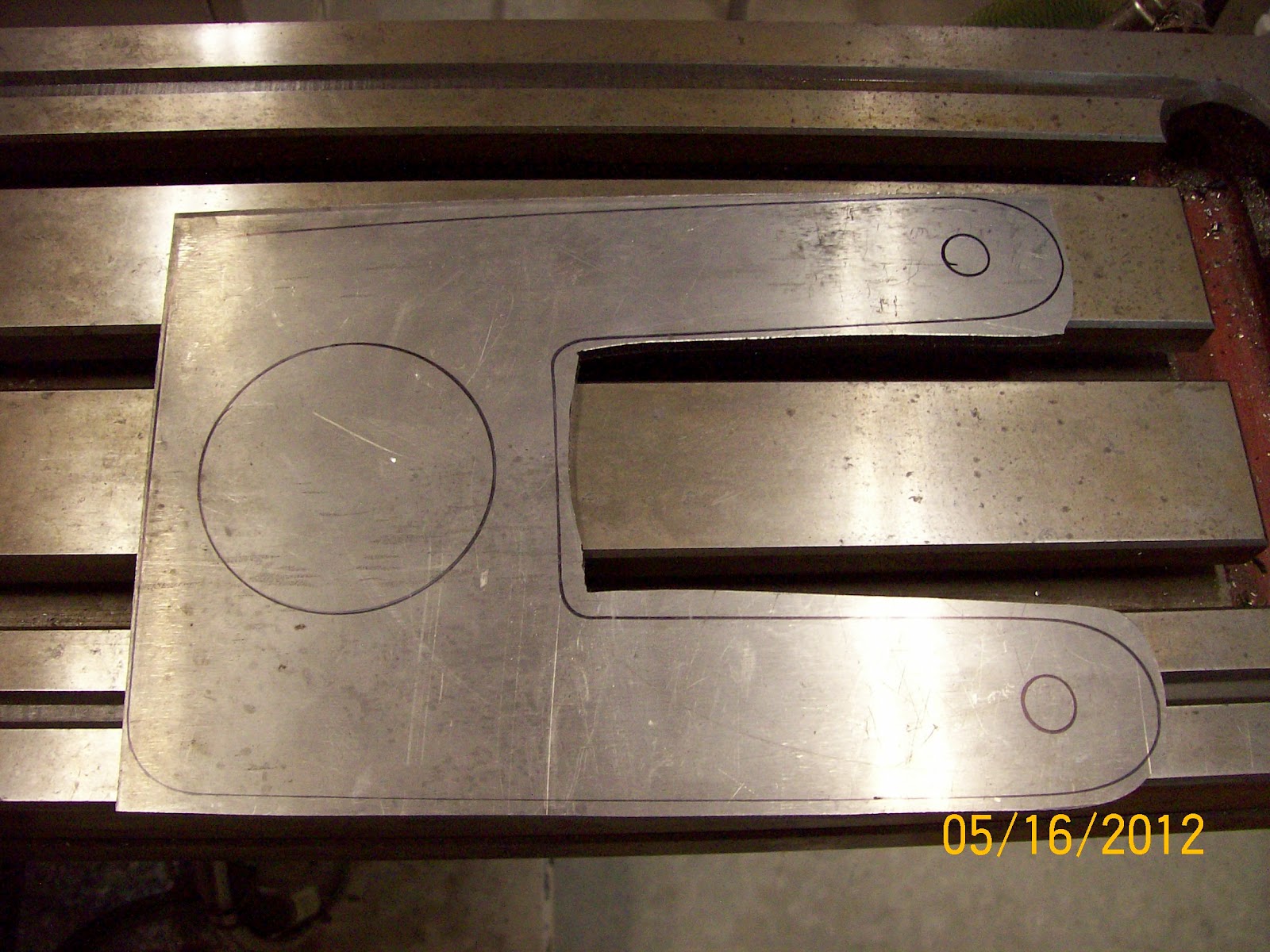
5. Wing Attach Plates - The outboard sections of the spar are held onto the main center section by 4 chromoly 4130 steel plates. Here is a pic of one of these that I got from George. The lower hole was apparently reamed too large and it is therefore not useful:
At one point I took this part and a .dxf drawing to a local shop that has a water jet system. It would have cost me about $25 per part to have them cut out with on a water jet system. That'd be easy - if I was only building one plane. But, as with anything in the "airplane" world the shop could not make these for me to use in production because their insurance carrier would drop them. Go figure. So, I have to find a way to make these parts (like all the kit parts) to keep this liability "in house."
So, here's my plan.
Step 1. - Make a pattern using CAD and CNC processes. Use that pattern to mark the basic shape of the part.
Step 2. - Put a rough cut piece of stock into the mill and locate on the 3 large holes, then machine those 3 large holes into the piece of stock.
Step 3. - Take the piece of stock with the 3 locating holes and place it onto a fixture installed on the mill. Next, CNC cut the remaining holes and profile.
Here is a pic of my 1st test piece after steps 1 & 2 are completed (the two small holes close to the big hole just happened to be holes that were already in the piece of material I decided to use for my test part):
Before I could move on to step 3, I had to make the fixture to hold the parts in the mill. It took the best part of one day to fabricate the fixture plate. Then, it took another day to machine the locating bosses into the fixture plate. Here is a picture of the CNC machine cutting the bosses:
Once the bosses were cut, there was lots of material to remove:
It was only 1/8" of metal to remove, but it sure took a while. Here's the (almost) completed fixture plate. Finally done:
Now, for step 3. Here is the test piece placed onto the fixture. Still have to come up with a way to hold the test piece to the fixture:
OK, ready for step 3. The test part is mounted on the fixture plate and the CNC machine is ready to cut the profile (initially I just had the CNC machine spot drill the smaller bolt holes):
And, here is the finished test part.
Turns out it was a "good news/bad news" deal. The good news is that I figured out how to get this all done. The bad news was that when I put the test part onto the spar, the holes didn't line up. You can see it here:
After studying this for a while I decided that this was caused by the fact that I started cutting these spar parts several years ago using George's patterns and drill jigs (before I even thought about converting to CNC production processes). Then I stopped making any parts for quite a while as I did my CAD drawings. During the CAD process, I made small changes to these parts to "clean up" many of the hand-made patterns that I got from George. In many places I made these changes to make parts fit together better, make parts symmetric, or generally just "smooth" things out. Well, enough time had passed that I'd forgotten many of these "tweaks". This was apparently one of them.
In the end I decided that I could make another test part with a hole pattern that would fit for my project (only). This would be a "one-off" set of parts just for this airplane. When I go back and make the next set of spar parts ALL from my CAD drawings this problem will be subdued. Here's a shot of the second text part (and it fits):
Next few days I get in the shop I hope to make 4 new parts from these:
6. Finished up 1st CNC project - Earlier this month I had a few days in the shop and I was able to finish up the CNC project that I was helping a friend with. This was a really good first project to help me get familiar with using my CNC mill. Here's a shot of the 20+ sets of parts for his business:
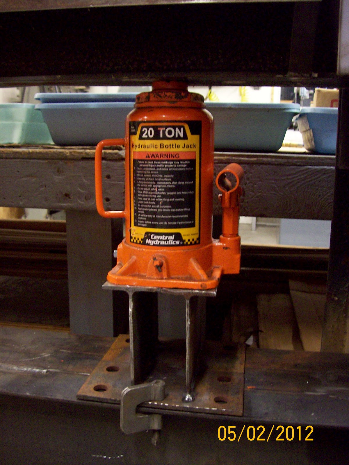
7. Press Brake Jack Stands - One day I was cleaning up a bunch of steel pieces and parts. I happened to remember that I needed to make some steel jack stands for the press brake where I had been using wood blocking. Here you can see the wood that I was using:
So, I cut and cleaned up a few more pieces of steel and welded these together:
These are a lot less "rickety" and should help make better parts since these stands won't be as "spongy" as the wood. There's another thing off the list!
8. MotionMaster Chip Blower - While finishing the last of the spar parts in the CNC router a while back, I decided that I really should have a jet of air blowing onto the area that the router is cutting to help evacuate the chips. It's not practical to run any kind of coolant on a router that has a vacuum table like the one I have installed on this machine. So, the next best option is just a jet of air to help blow the chips away and help cool the cutting tool (router bit).
Actually, dad helped me start this project when he was here in the shop with me in March. We got the air line run out to the spindle and collected all the parts to plumb it all up - but just didn't get to finishing it (with all the 100 ton ram business going on). Well, recently I decided that I'd walked around that little mess for the last time. I put on the "Gitter Done" hat and finished up the job. Here's a shot of the plumbing on the spindle plate:
The brass valve is used (obviously) to control the amount of air flow. In this pic you can see the nozzle sticking out the bottom of the plate that holds the dust shoe onto the bottom of the spindle:
I'm anxious to see how it works the next time I fire up the router. I'll let you know.
9. Motorbike Rides Again -
On the lighter side, the project to get the motorbike going again for the girls is completed. The UPS truck "finally" showed up with the new rear wheel assembly. It only took a few minutes to install the wheel, put on the chain tensioner, and adjust the brakes. Here's the new wheel:
And, the happy customers:
That's all for this update. The busy summer is already upon us. When I leave to go to work next week (Jun 2nd) I will be home very little until the 1st week in Aug. Since I won't have any time in the shop to get any Prowler work done, the next update will probably not be until this fall. I hope you all have a great summer.


