Well, it's hard to think that this is only my second real post for this year. But, unfortunately, this year my plate kept getting stuffed with projects and other responsibilities that had to take a higher priority than Prowler Aviation. So, I haven't made much progress with respect to my airplane building - or rebuilding production of the Prowler kits. I have, however, beat the start of the rainy season here in NorCal and just finished several key "projects" that I needed to get accomplished before winter and falling water set in. These projects weren't (mostly) directly related to building Prowler Aviation. But, now that I do have these things out of the way, I did get back in the shop a few times this past three weeks and started working on the airplane again. Heck, it's been so long since I've done anything related to the Prowler that it took a while just to figure out where I'd left off at.
Despite my lack of work on Prowler this year, there still has been other Prowler work going on around the country - and around the world for that matter (thanks to our French Prowler connection in Francis and Robert). Here's the Prowler related items that I'll cover in this update:
1. Ray's Painting is Almost Done -
2. Steve's Reduction Gear Work -
3. Bryan's Progress -
4. Status Update on Francis & Robert's Prowler -
5. Bud's Latest Report -
6. Making the 1st Prowler formed parts using psuedo-hydroforming -
7. George's original Prowler Kit #6 -
Here's the list of other projects that have needed my attention this year:
1. Rebuilding a Buddy's CNC Mill -
2. The Yoder Power Hammer for Another Buddy -
3. Retaining Wall -
4. Shop Heater -
PROWLER ITEMS:
1. Ray's Painting is Done - In October, Ray let me know that the painting was getting close to done and that he'd finished using the wing tree (stand that holds the outboard wing panels) that he borrowed from George. I drove to LA for work that week and went out to Ray's hangar to pick up the wing tree and see the painting progress. Here's a shot of the fuselage with the base coat on, waiting for the clear coat to go on:


2. Steve's Reduction Gear Work - Shortly after my last update, I received an email from Steve asking about the construction of the reduction gear and explaining that he had begun to loose the ability to feather his prop. He decided that the likely culprit was a brass sleeve that is used in the PSRU prop shaft that provides for rotation of the shaft and also sort-of "seals" the prop hub oil for delivery to the prop hub. There is a steel tube that is pressed into the end of the prop shaft that is also seated into the brass sleeve pictured below.

Here are some excerpts from a his last email to me:
I wound up replacing the tube with a length of 7/16 inch 4130 stainless tubing. I polished the ends and measured the OD, then took the PRSU to a machine shop and had them increase the ID of the bushing in the prop shaft to .007 over the tube diameter (Ray recommended .005, George recommended .01). I tried to increase the ID of the aft, engine mounted, bushing by hand using a succession of reamers, but in the end, the hole wound up being off center. I rented a slide hammer and removed the bushing, took it to a machine shop and had a new one made.


3. Bryan's Progress - I will let Bryan describe his progress of late in his own words. This is from a recent email update:
You ever drive by an empty lot and then again a week later and there was a house there? My, that went up fast you would say. Then for the next year and a half you realize there are subcontractors there every workday. Will they ever get done?
This is my foray into the 90% done 90% to go status. I spent 4 weeks straight working 14hrs a day on the airplane and it looks like nothing has changed.... However I did get the VP computer wired. Then wired all contactors and additional CB’s, built the throttle/prop lever and built the main wiring harness between all the sub black boxes. And to top it all off I re-skinned the horizontal stab.
I did run into some problems tho... I had painted the cockpit with an aircraft fabric paint (the paint came in identical cans) so had to gut the interior and strip the old stuff, then re-spray everything.
I will have to pull the AP servo from the wing because the unit is now old enough to not be compatible with the new Dynon system I have installed. I will also have to redo my capacitance probe wiring due to a misunderstanding in the directions for its installation and finally, somewhere, there is a disconnect in the left cowl flap wiring...
The first picture is of my final design for an over center canopy latching system.


4. Status Update on Francis & Robert's Prowler -
The guys from France are making good progress on their Prowler. I've gotten a few emails from Francis this fall with pictures to update me on their status.
From email update in Sep:
Some news for you, we have finished de-riviting and reaming the center section spar! We are only at this progression because on the main renter of the hangar want to paint it! Good idea, but we have to move also the jig to a better place for the other airplanes. We think we will be able to start the alodine process "nous meme" (ourselves).
I think in a box whith plastic film (i have the alodine, but not the deoxidine for the moment). Yesterday we have bolted the jig to the floor, but some adjusting will be nescesary. We shoudl be done by Saturday, I think.
From email update in Nov:
hello Todd!
Robert has built two wooden boxes for the alodine process! One for the deoxidine (etching) and the other one for the alodine. Robert did make plastic sheetings but one leaked. They are triangular to limit the "volume" (of solution needed). I think it's not impossible than we dip the spar in 1 or 2 weeks. That's all for the moment, Francis
Here are the most recent pictures from Francis:


5. Bud's Latest Report - Here are a few quick updates from Bud on the status of his airplane.
From a short email update in Jun:
This (photo) was taken a week ago. I am practicing formation with a former Navy fighter jock, who has his Velocity rigged with cameras to produce 3D videos.

In a recent email to Ray:
Congrats on finishing the painting; it was a long struggle. I can't wait to see the results. It will be some time before I can afford to paint mine. I finally flew today with the new elevator counterbalance. The weight increase was 4 lbs and I have neutral balance on the elevator. It handled very well and if there is a difference in the feel, I can't detect it.
My tank quantities are: fuselage------ 11 gal
fwd mains--- 18gal ea.
aft mains----- 12.5 gal ea.
I used a label maker, with black on clear, for the quantity, and stuck it on each cap. My fuselage tank is filled by transferring fuel from the aft mains. This allows me to transfer more fuel in flight into the only tank with a flop tube.
Thanks for the updates, Bud. It's great to get news from someone that is currently flying his airplane. I think that you are the most active Prowler flyer right now, so I really appreciate knowing how you and the airplane are doing. Please continue to keep the reports coming!
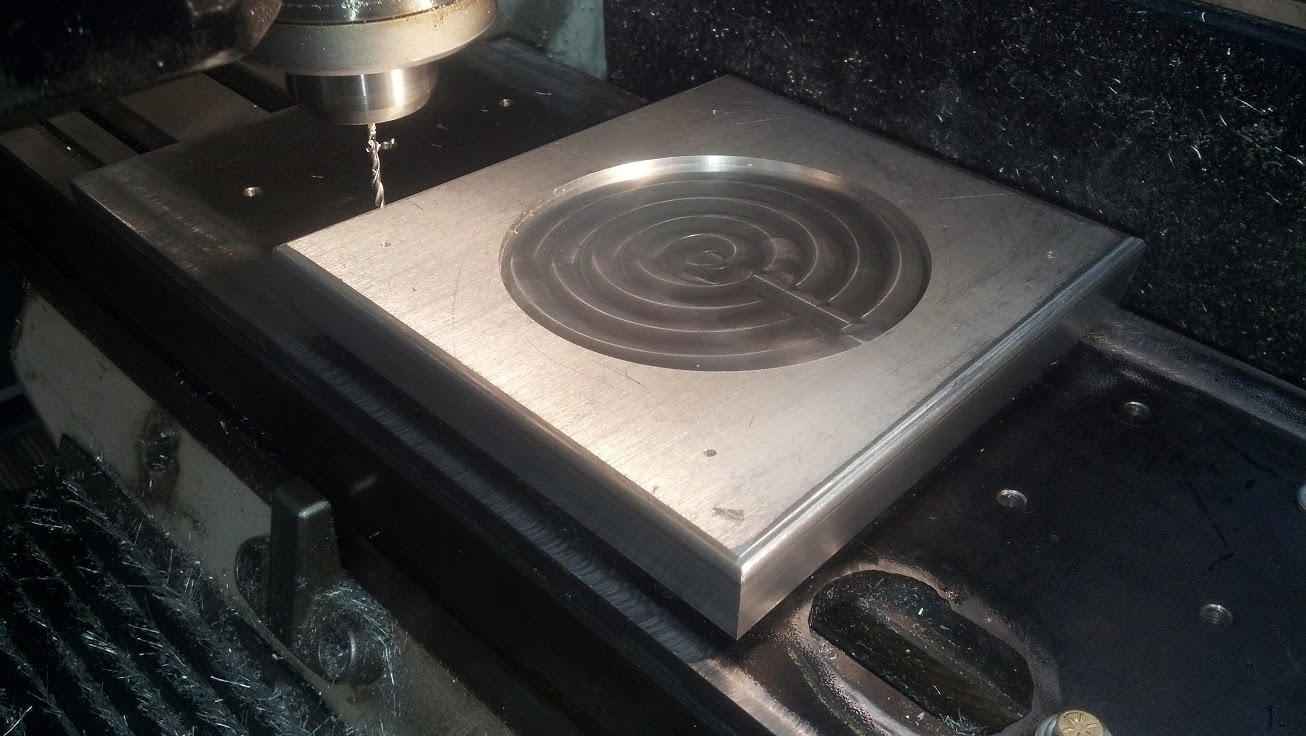
6. Making the 1st new Prowler formed parts using psuedo-hydroforming - So, after nearly a full year of doing just about everything else besides working on the airplane, I finally got a few days in the shop to start making my first bending die. From here on out, the building of the 1st new Prowler will be a repetitive process of cleaning up a CAD drawing for a given part. Then, doing the CAM operations and posting out the tool paths to cut a new die for that part. The dies will probably all be made from 1 inch aluminum. When the die is complete, the next step will be to do the CAD/CAM to cut the flat part blank from 2024-T3 that will be used to bend around the die to make the part. When both of those are done, it will be placed into the 100 ton hydraulic press that I spent most of last year building/rebuilding/constructing. After the part comes out of the press, it will be test fit onto the airplane. If it fits, then move on to the next part. If it doesn't fit - then I will have to repeat the above process until the part is correct.
The next parts that I really need to have for the airplane are the tip ribs. However, the tip rib CAD files are a little complex and the complex curves of the ribs will be a little more difficult to bend without adversely stretching or breaking the flanges of the tip ribs. So, I decided to pick a a less complex part for my first endeavor. That way I can see if the hydraulic press will even work and be sufficient to make these parts at all. If it is, then I can also build up a little experience and a little confidence before tackling the wing ribs.
So, the part I picked to do first is one of the transverse bulkhead parts that is under the cockpit floor and just aft of the main center section spar. I liked this part because I am relatively sure that I can get the size correct on the first try. It also has straight sides which are easier to machine for a 1st attempt. Additionally, the part has a lightening hole so that I could see how well my bending technique will also press in flanges for the these. Here is the part location in the airplane:


7. George's original Prowler Kit #6 - Within hours of leaving the house for my last trip to work before Christmas, I got a call from a gent telling me that his son had bought a Prowler kit some 20+ years ago and that it has been sitting in his warehouse ever since. He was closing down his business and had a new tenant moving into the building on the 1st of the year and needed the kit gone before then. The only remaining time that I had to help secure this kit was the Sat-Mon before Christmas. With this compressed time frame, the logistics of getting and shipping a kit was going to require the assistance of an expert. I was also going to have to find a new home for the kit. Having years of experience driving a FedEx delivery truck, and living generally on the right half of the country, I gave Bryan a call. He was interested and thought that he might have time to meet me there. There was near Fort Lauderdale, FL.
I could not be entirely certain how complete the kit really was. All I had to go on was the verbal descriptions of the gent that had called me. After several phone conversations, we were able to negotiate a (pretty much) sight unseen deal for the kit. It was a bit of a gamble, but the price was fair and seemed to be worth a trip to south Florida. All that was left to do was find a way to move the kit. We decided to move the kit to Byran's place since it was the closest place either of us could think of to store it without a lot of extra cost. After researching several options, it seemed that everyone wanted at least $1200-$1500 to start the conversation about a one-way vehicle rental. With the kit un-crated and laying in pieces, we would not have time to try crate the kit and then also get a bid on U-ship.com to get it shipped before we both had to be on our way back to our next schedule commitments.
Then, I did a quick Kayak search for a larger mini-van. I found one good potential one-way rental for a Dodge Grand Caravan. It turned out to be the best cost option, and seemed to be the perfect solution - except maybe for the 15hr drive from south Florida to Memphis. But, it fit the budget and we took an educated guess that the kit would fit in the van. So, the plan was hatched. I would get to FLL on a redeye flight from LA and Bryan would do the same from the end of his last trip. I got there first and picked up the rental. Then I picked Bryan up and we made our way to where the kit was located. We showed up about 10am and started stuffing the van:


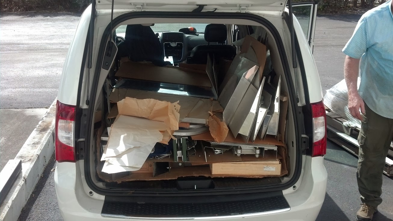


It turns out that this is the original Prowler kit #6. It has changed hands at least 4 times (including the original sale). I must say that it was all that I could do not to just "claim" this kit for my own. But, if I got this kit, I would start spending all my time and money working on just this one plane. Conversely, by completing all the CAD and CAM work and fabricating every part myself while I build my 1st Prowler - I am, in essence, building Prowler aviation "the company" while simultaneously building a Prowler plane. I am really trying to stay as laser focused as I can on getting this company rebuilt for production and get the company making kits again. Getting distracted by working on an earlier kit will not get me where I hope to go. This kit, however, is still a very viable and buildable kit. More to follow.
OTHER PROJECTS:
Now, for more info on a few of the other projects that consumed a lot of my off days from the "day job." While it may not be immediately apparent, these projects are remotely related to Prowler Aviation in one way or another - enough so that I had to move these up the priority list to get them accomplished ahead of working on the plane. I am happy to say that each of these projects is now finished and should not take much more of my time - if any at all.
1. Rebuilding a Buddy's CNC Mill - As you know from previous posts, I have a buddy that I committed to helping get his milling machine fixed up an running. This time I can report that the machine is up and running well. This was really a very big project and I am happy to have it checked off the list. The best part though, is seeing my buddy make parts from a machine that was previously not much more than a huge paperweight.
In a previous post, I reported on getting the control fixed and installed on the machine. With that done, it was time to start the re-wiring of 75% of the entire machine. Here is the main component cabinet just after the height of demolition. It also shows that the transformer has been removed and re-mounted to the outside of, and below, the distribution box:


In the end, this was a pretty big project. I put in a lot of hours doing research, programming the PLC and troubleshooting wiring diagrams. But, it was also a very rewarding project. I learned a lot and (re)built a machine that he will be able use to make parts for his business for years to come. In fact, he recently made his first run of parts using the mill and is very happy with how it operates. Nice to see.
2. The Yoder Power Hammer Machine for Another Buddy - With all my extra spare time, I finished the bulk of the CAD work for another buddy to complete the machine he needs to make parts for his business. Here are the most recent shots of his machine being built at a local industrial fabrication place:


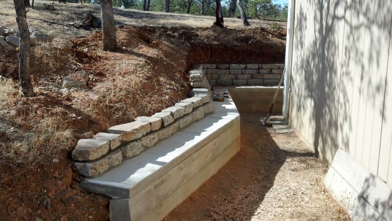
3. Retaining Wall - In past updates I have posted ad nauseam about all the retaining walls that I have built and still need to build around the shop. I am happy to report that the most urgent of these walls that needed completing is finally done. The bank behind the shop had been eroding off for years and the mud had built up above the wall sill to where the water was coming into the shop. After the hot weather broke this fall, I got motivated and worked tirelessly to get this wall finished. I also had to get the landscaping done behind the wall to get rain and water to shed away properly. Here is the beginning of the final push to get this wall done:


4. Shop Heater - I have reported previously on my plans to get a real heater in the shop. For several winters now I've been using a torpedo heater in the shop that burns kerosene. But, those heaters are noisy and the exhaust gets released directly into the shop - so I really wanted to get a better heating system. In the previous update I reported on completing the conversion of the furnace from natural gas to LP gas. With that done, there were 4 steps remaining to get this furnace working:
1. - Wire the furnace with a thermostat and get 120Vac power hooked up to it;
2. - Test the electrical/electronics and the gas valve operation;
3. - Get two 100lb LP tanks certified and filled;
4. - Install the 6" B-vent exhaust pipe thru the ceiling and roof and install the storm collar and diffuser at the top of the pipe.
The first thing I did was wire the furnace, put the thermostat on heat, set the temp high to see if the pilot light igniter was working. It was, but I found that the ignition module was clearly stamped with the words "For Natural Gas Use Only." Great! So, after some quick research I found out that the box I needed would be $150+ (if purchased new). That's more than I paid for the furnace, 1 LP gas tank and the LP conversion parts all combined. Obviously, that wasn't going to happen. So, like every thrifty discount hunter, I hit eBay and found one of the (used) LP igniter boxes I needed for $40 - shipping included. Now, that's more like it! So, a week later I had the new igniter installed, the old one boxed and listed on eBay. (It eventually sold for $30 - for a total cost of $10. Sweet!) Here is the unit with the most of the work done. The thermostat in the picture above was only in that location for testing. It was later moved to the other end of the shop from the furnace.

Next, I noticed during testing that the fan that blows air across the heat exchanger was not turning on. That's not good, since you can overheat (and eventually crack) the heat exchanger. After a little more research I found that this fan is controlled by a simple 120Vac delay timer (sensed off of the thermostat signal to turn on the heat). So, I pulled off the junction box cover in the back and eventually figured out that I had re-wired the timer incorrectly while I was removing and re-installing the ignition box discussed above. Rats! Well, it was an easy fix - once I figured out what needed fixing.
At this point, I was satisfied that the furnace would probably, actually, really work. So, the next step was putting in the exhaust pipe. That is a pretty straight forward chore. You just have to cut holes big enough in anything combustible to allow for at least 1" of clearance everywhere from the vent pipe. After getting full of sawdust and insulation and playing tinker toys with the sections of the vent pipe - here is the net result:


All that was left to do was turn on the gas, flip on the thermostat, turn the heat setting on the thermostat way up......then cringe, duck and hope for the best. Happily, there were no explosions and the furnace worked mostly fine. I did have to tweak each burner air shutter (one at a time) to get a nice, complete combustion. When that was done, the furnace worked pretty well. It is really nice to finally have heat in the shop that is quiet and can be controlled by a thermostat. It will make working out in the shop in the winter cutting dies and bending wing ribs much more comfortable.
SUMMARY - Well, there it is. That is pretty much everything that was going on here that is even remotely related to Prowler Aviation. If my first attempt to press out an airplane part goes well, then this will become the majority of my work for the next year. Also, if this process works, the next parts that I will fabricate will be the wing tip ribs. That will allow me to complete the installation of the wing spar into the jig. Once, that is complete I will have to take the spar back apart and alodine all of the individual pieces before priming (I have to try to catch back up to Francis and Robert!).
If I find out that this press is not sufficient to form these parts, then I will have to focus on finding or building a larger press. I know that the current 100 ton press will be big enough to form some parts of the plane. I'm just not sure if it will have the force necessary to make some of the larger parts. As I get more experience at making parts with this technique, I will be able to determine where I stand. Since most of this 100 ton press came with the stuff that I got from George, it didn't cost me a lot to develop it into a useable press to do this pseudo-hydroforming process. I always planned on eventually making a larger press. But, by starting with this I will learn about this whole process and that will eventually help me create a good design for a larger press, later on. In the end, it will be helpful to have more than one press to make parts in production, anyway. I envision having one large machine that will be able to press any and all of the parts needed for the kit. Then, a smaller press that can be used to speed up production by pressing just the smaller parts. This should all become evident within the next few months.
I am glad that I was able to get this blog update finished for 2013 so that I can start 2014 off with a clean slate. I am going to fight to keep my plate clear of stuff that is not directly related to Prowler Aviation next year - in a effort to try to make some decent progress on the wing framing. I am also going to try my best to make my blog updates more frequent and shorter. I was able to do that fairly well in 2012 and it really works out better for creating these updates. After updates like this, I feel like I've written a novel, and you all probably feel like you've been reading one - if you've even made it this far!
In any event, thank you for stopping by and keeping up on the progress of the new Prowler Aviation. See you next year.


