Hello Everyone,
As I mentioned in the last updates, there was not a lot going on in the Prowler world between late 2020 and early 2021. Also, I was not working the "day job" because of CoVid. So, I took advantage of the time to get some machine fixing done.
CAUTION ! - This blog update does not contain any Prowler related material. If you don't care to see me talk a lot about repairing old machines, you might want to skip ahead to the next blog update.The (Seemingly Never Ending) Hardinge CNC Lathe Project This machine has been sitting in the shop bay where I normally work on projects for so long, that it starting to become a permanent fixture. I really need to get this machine out of the shop! (I need the space!) So, I put my head down and charged forward on several "hit list" items on this never ending repair/remodel/restore project.
Tool Turret - This CNC lathe originally had an 8 position tool turret that could automatically be lifted up, rotated to a new tool, and then locked back down into position. There were an amazing amount of special parts that worked in concert to accomplish this seemingly simple function. When the F8025T control was retrofitted to this machine, the old control was removed and this rendered the automatic tool selection turret unusable.
The retrofit installer's solution was to bolt a bar of steel to the turret and turn it into a gang bar style tool setup. That did work, and there are many gang bar style tool machines out there. However, the range of motion of this machine in the X axis is a little limited (short). So, it cuts down on the number of tools you can mount onto it.....depending on the size of your stock, etc. The other problem was that air was no longer ported to the side of the piston to hold the turret down firmly, so it allowed for some tool movement - affecting accuracy.
I really didn't like this idea of a gang tool bar and I wanted to figure out a way to make the tool turret usable again. However, to get this to work again automatically with the F8052T control was going to be a real challenge. But, even if it wasn't automatic, if I could just get the turret to pop up and rotate by hand, that would be a huge improvement. After some more tear-down of the cross-slide and tracing some air channels in there I decided it might be possible. Using a small number of the original parts, and adding an "air switch" the turret could maybe be used again to select new tools in a manually selectable fashion.
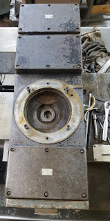
In it's original form, what made the turret lift up and lock down was simply air pressure ported to a piston that was integral and attached to the tool turret. If I could figure out a way to get air routed properly to that piston, I could make it move again. The hole in the cross slide in the picture below is essentially the "cylinder" of a pneumatic actuator:
This (below) is the air piston that is integral to the turret. The tool turret plate is attached with the nut on the right side. The black stripe around the edge of the piston is the large O ring that seals the piston inside the cylinder:
Here is the piston mounted into the cylinder. The tapered dogs on the left and the right are what align the turret plate to the lathe and help hold it in position when air pressure pushes the piston down. The turret plate rotates using the bearing on the inside diameter you see here:
Put it all together and you get this:
Now, to move the turret up or down, air pressure has to be applied to either the bottom and vented off the top, or vice-versa. That required finding the original ports that would take the air pressure to the top side and bottom side of the air piston. Once i found those, I simply had to plumb them to this special "air switch" that I found online:
This switch has 3 positions: 1- a position that just vents all the lines; 2. - Port A pressurized and port B vented; and, 3. - Port B pressurized and port A vented. Here is the air switch mounted into the machine (before paint):
I added pressurized air to the machine and got this:
YES! It works!! With this setup, the machine can now be programmed to work with one tool, then use a pause routine with a message for the operator to select the new tool, then press the cycle/start button to continue operation. Sweet!
Spindle Encoder Cover - A spindle motor encoder is a device which sends feedback information from the spindle motor back to the machine control (computer). It is a rotatory device that is mechanically linked to the spindle motor and always turns whenever the spindle motor turns. It essentially sends a stream of electrical pulses to the control computer and the computer can count these pulses and accurately determine the spindle speed, direction of rotation and angular position. Here is the spindle encoder on this machine:

As was the case with so much of this machine, when the new control was
installed, many of the original supporting components were left in place
and just disabled. The spindle encoder system was no different. In
fact, as I started to troubleshoot this system, I found the spindle
encoder cable cut in half and the ends of the cables simply stuffed into
cable way tubes! The other thing I determined while troubleshooting this system was that the original encoded was not working correctly (probably why the cable was cut).
The encoder you see in the picture above was an older, used unit I found online to replace the original. Once installed and working, it needed a cover. The original cover could not be found, so I decided to fabricate a new one. The first step was to make a plate to fit the mounting surface on the machine. Using a picture of the pad and scaling it in the CAD software, I was able to use the CNC mill to cut this plate out:
Then, I found a piece of aluminum tubing the correct size and cut a piece to the right length. The one mounting hole in the flange was going to get partially covered by the piece of round tubing, so I used the mill to cut a partial hole (groove) in the right place:
So far, so good:
Add a cover and here is the result tack welded together:
I will get this welded up soon and finally get it installed on the machine.
Collet Closer - The next system on this lathe that needed attention was the collet closer system. This machine was designed to use 5C collets and the are tightened by an air diaphragm system pictured below.
When I bought the machine, the parts V & X shown in the picture below were missing. Fabricating these parts was going to be a pretty big job.
Fortunately, the buddy I bought the machine from was converting one of
his other Hardinge lathes over to a newer style collet system and could
give me these parts off of his machine. So that part of the system was
taken care of. Here they are installed on my machine:
With that done, I turned my focus another part of this collet closer system. The air glands and piston. While researching this part of the lathe, I learned that this model of collet closer uses a lot of air - even when they are new and working correctly. The reason is that there are not any seals in the system between the rotating and stationary parts of the closer - only tight tolerance air glands that are located in part where the air lines attach in the picture above (on the left side of part Q). I decided to go through the entire part Q and replace all the seals, just to make sure it won't give any problems later. So, here is a picture of the closer piston taken apart:
I actually posted a YouTube video of this work, in case it might help someone else refurbish their unit some day. If you are interested, you can see it here:
Vari-Grip Collet CloserWith the unit re-sealed, I installed it back onto the machine and hooked up the air lines:
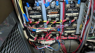
Now, I had to resurrect the part of this system that applied the air to the closer to get it to open and close. In it's original form, this collet closer was controlled by a switch on the old, 1970's vintage controller console - which is long gone. What that switch did, was control two solid state relays that I had earlier relocated to the new electronics cabinet. You can see the bank of relays in this picture:
So, all I had to do was to source a new switch and wire it to control those same 2 relays. Then, I would have to mount the switch in a convenient place for the operator to control. I ended up finding a rotary switch and then fabricated a switch box with a switch guard to mount to the front of the machine. Here are the parts that I fabricated and the switch:
The parts assembled and before paint:
And, here is a picture of the switch box mounted to the front of the machine:
Just below this new switch is the solenoid compartment. Each of the two solenoids controlled by the new switch are in this compartment (pictured below). This system is called "Vari-Grip" and what it means is that it can adjust how tightly the collet clamps down on the parts being machined. The "Vari" in this systems simply comes from an air pressure regulator that controls the amount of air pressure sent to the "Grip" part of the system. You can see this pressure regulator in the upper left of the picture below.
The solid state relays control two solenoids that are located the the
far bottom left of the pic above. The two larger black air hoses in
the far left side of the picture are the air lines that pass through the
machine walls and end up coming out behind the headstock and go to the
collet closer shown in a picture (several) above. This was my first experience dealing with a collet closer system and I learned a great deal about it. I'm also happy to have it rebuilt and done!
Coolant Tank and Pump - Well, of all the repairs to this machine so far, it was this coolant tank system that almost broke me! In order to get the old tank out of the machine, there is a sleeve between the catch pan and the top of the tank that must be pulled upward. In order to pull that sleeve up, I had to remove a plug that had been welded into the bottom of the catch pan. Removing that plug was a bear!! I played hell trying to get that thing cut loose and pulled up, out of the way. I heat it, beat it, ground on it, pried on it, and it wouldn't budge. Finally, I had to weld bolts to the inside and then block up a strong back to pull it up with 3/8" nuts. Just look at this thing:

BTW - wrestling with this thing was made worse by the fact that it was directly under the bed of the lathe. Once I got the the plug removed from the catch pan, I was able to remove the sleeve from the hole in the top of the coolant tank can see in this pic below. This pic is of the coolant tank after I remodeled it to about 1/3 of it's original size and welded some fittings into it. The fitting with the hose on it is the pump pick-up. The one below that is for a drain valve. Here is the tank while testing my welds for leaks with water:
The same tank after some clean-up and some paint:
Here is the tank put back into the machine with the coolant level indicator that I made viewable from the back of the machine:. There will eventually be a panel in place to cover this tank access with a window for viewing the coolant level:
Here is another view of the tank installed in the machine. The pump is on the right side and the lower left side has a drain valve on the bottom and a tank suction for the pump just above. You can also see the sleeve that comes down from the catch pan and seals into the hole in the top of the tank:
To get the coolant pump to work both in manual and automatic (activated by the part program) - I had to find the control wires and route them to one of the solid state relays in the servo control cabinet. In this case, it is 5CR, the relay in the top right that is wired to the coolant pump:
With that wiring completed, I did a test of the system in this video:
The last step to the coolant tank work was to fabricate a new screen to put in the bottom of the catch pan (instead of a plug) to catch fine chips from making their way into the coolant tank. I found a piece of pipe the correct size, welded a steel screen to the bottom and put it in place:
After getting the plug out of this system, the all was academic after that. Glad to have this system working again.
Control Cabinet - There were several modifications that I wanted to make to how this control was mounted and located. The first one was that I wanted to install a PC that could be used to transfer programs to/from the F8025T. The second thing I needed to do was to move where the control was mounted to the machine, because 2 of the main cables running to the servos stuck out of the side of the control cabinet in a way that the door by the operator's station could not be closed all the way. Then, as I got more into this part of the project, I also decided that the control needed to be mounted to a rolling cabinet that could be disconnected when the machine had to be moved, and then moved as needed.
As I worked on a lot of the parts of this machine that I've discussed earlier and in previous updates, I was keeping my eye out for an enexpensive PC and LCD monitor. I eventually found both and set out mount them to the existing control box. I made a bracket that fit the monitor and used that to mount it to the top of the box. You can see that here:
I also found some sheet metal and formed up a keyboard tray that I mounted at an angle and put a small flat shelf for the mouse pad. It turned out pretty nice and it all worked when I plugged everything in and tried it:
Once I had this finished, I started thinking about moving this machine. With all this "stuff" attached to the control box, how do you move it? How do you set it down, without breaking something off or having to take it all apart? I had to find a better way.
About that time, I came across an old steel cart that was like a podium on wheels. I looked it over and decided that if I could cut it off the right height, weld the right plates and brackets to the top, then I could mount the control on it permanently. With this design, moving the machine would be much easier - just removed a few canon plugs, pull a few power wires and remove a couple of bolts and the whole control cabinet would be able to be rolled away from the main machine. Then, the main machine could be lifted with a forklift and moved as needed. I liked the idea. After some cutting, heating and beating, I had this:
I even put in a shelf to mount the small footprint PC to inside the cabinet. The other nice thing about this plane is that there will be storage in this rolling cabinet to put machine manuals and spare parts etc.:
When, I put it all back together again, this is how it looked:
Nice! So, now that I could move the control around more easily, I wanted to work on positioning it so that the control cables to the servos would not interfere with the doors on the machine. I rolled the control back about 8 inches an now the cables to the servos will pass behind the canopy on the machine. You can see in this pic where the control cables plug into the blue connections on the control box:
The only modification needed to make the control stay in this position can be seen in this picture:
The black square tube with the flange on the right is connected to the control box, the holes in the machine base on the left is where it used to be bolted together. All I would need to do is fabricate a plate with hole patterns in the right places and bolt it all together. Since the weight of the control was no longer supported by this steel tube, it did not have to be very beefy or strong. All it would do is hold the cart in place, essentially. Here it is, also painted up in black:
Now, the control is positioned well and sits pretty much like you saw 3 pictures above.
Paint and Panels - With the bulk of the repairs done to this machine, it was time to start putting the panels back on and I wanted to put a coat of paint on the base to clean it up a little. I did not have all the missing panels, several were removed and not on the machine when I got it. But, I did have a little collection of panels that I'd gotten off of other machines in the past or found various places. I was able to find enough to replace all the panels on the machine - except one. Here's the front of the machine:
There was a panel that covered the main spindle motor originally, but it has long since been removed and lost. I decided to leave the machine without replacing that one cover. Here is that end:
Here is the right end of the machine and the back with all the panels in place and painted. The panel that covers the coolant tank in the back was the last to be fabricated, painted and put on the machine:
So, as the machine currently sits, I have a little painting to do - I want to paint the uprights on each end of the machine and repaint the doors black (they are sitting on top of the machine, up-side-down in this picture):
I have to decide if I want to spend the money to put plexiglass back in the doors. That'd be a little expensive, and I only want to do it if there is real need for it. I have more thinking to do on that topic.
There is also a little more sheet metal work to do on the control cabinet and that needs to be painted black. I want to add some shelves in the cabinet for the machine manuals and paperwork. I also would like to have a space to put some of the old/spare parts from the machine.
I will report on these items in a future update. Thanks for checking out this project. I hope it was informative and maybe a little entertaining.