Well, every time I sit down to type up some narratives about what's going on here, something comes up that needs attention and I end up having to put off the blog update. Unfortunately, it happens a lot, much more than I like. But, the reality is that, the blog updates are the easiest thing for me to "move to the right" and find time to give attention to emergent issues that come up. The downside to that is that more and more info gathers up for each blog update until they get to be very large updates; also something I don't particularly like. Anyway, I got a break in the action for a few days and I'm gonna "git'er done"!
Items for this update:
1. Ray's Aircraft Paint
2. Formed First Part Using The 100Ton Rib Smasher
3. French Prowler Progress
4. Bryan's New MLG HCAB Becomes Standard Prowler Equipment
5. An Update From Bryan
6. News On The Original Prowler
7. Another Kit Rescued From The Recycling Bin
8. Aircraft Available
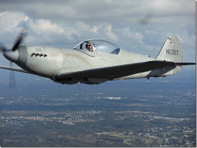
1. Ray's Aircraft Paint - I received a CD in the mail recently from Ray. It was full of pictures from a photo shoot of his airplane that he and his painter (Andy) did one early morning. Doing the shoot using early morning light gives a diffused light and not as much glare. Ray did an amazing amount of research to find an authentic paint scheme and authentic (as close as possible) paint colors to WWII period military aircraft. The results of both of these jobs combined is amazing! The paint job was extraordinary (nice job Andy). Enjoy these:


Beautiful aircraft, Ray! You have done one top notch, outstanding job building your airplane!
2. Formed First Part Using The 100Ton Rib Smasher - In the last blog update I outlined how I made the die in preparation for making my first Prowler part using the pseudo hydroforming process. After machining the die, the next step was to CAM out and cut blanks out of 2024-T3 to use make the parts. Here they are after cutting:


I have been researching what I can do to make this process work a little better. I think I've found several things that will need tweaking: 1) the rubber that I found to use is likely too soft and not thick enough; 2) the total amount of rubber packed into the box is too little; 3) The size of the pocket in the top of the die to make the hole flange was not quite large enough; and 4) the press may be too small for this size of part. Yeah, believe it or not, 100 tons may not be enough force to form this roughly 10" x 10" part! And, this part was made from only a .032" stock. A part from .040" will be even harder to form.
The other problem is, even though 100 tons may not have been enough force to form the part, it was enough force to bend the press - and not in a good way. Check the "new" shape of the upper H frame of the press:

3. French Prowler Progress - Francis and Robert have been doing a great job and making really good progress on their Prowler. Here is an excerpt of a recent email from them:
Hi Todd,
First we wish you an happy new year.
We would like to keep you updated on how things are going on here.
Main spar, wings spar are re-drilled and we have treated the main spar in alodine just before Christmas (att. pics.).
We hope to start riveting on January and then i will send you more pictures for your blog.
All the best for you and for your family
Francis and Robert
Here are the associated pix:

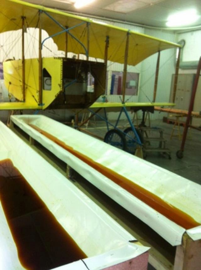


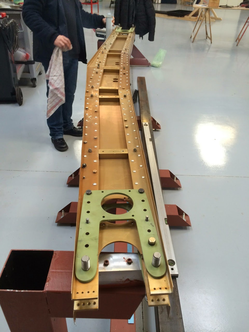


Great progress on your airplane fellas. Please keep the pix and info coming!
4. Bryan's New MLG HCAB Design Becomes Standard Prowler Equipment - A few years ago, Bryan came up with a great design for the Main Landing Gear Hydraulic Cylinder Attach Brackets (MLG HCAB) that performs the same main function (to hold the inboard dead end of the MLG hydraulic actuating cylinders), but it also incorporates the lower portion of the negative G mod that is required. Since Francis and Robert wanted a set for their aircraft, and I need a set for my airplane and there are two kits available that can use this new design - I decided that I should fire up the CNC machines and get 4 sets of them fabricated.
As with all things CNC, the first step is to have a drawing. Then, you turn the drawings into tool paths (which is the CAM function). However, before you can even finalize your drawings, you need to use some imagination and decide how you will fixture (hold) your parts while you machine them. Sometimes, the drawings (and eventually the tools paths) change depending on how you can best fixture your parts. So, you have to get a bit ingenious occasionally as to how you can best accomplish this.
In the case of the parts for the MLG HCAB's, I decided to use existing holes in two of the parts as tooling holes to fixture the part and in the other parts just pick some out of the way spots to put some tooling holes. Then, I added the correct hole drilling operations to the original CAD drawings to place the tooling holes correctly.
With the decision made of how to fixture the parts, the next obvious step is to build the fixture. Here is the plate I made for this set of parts. I have bolts into T-nuts holding it to the mill table:


You might also notice that the blue CAD version of these parts (above) has a large lightening hole in the vertical parts and the fabricated pieces do not. That is because I needed/wanted to use these holes to double as tooling holes. Same thing for the upper hole which is used to hold the inboard end of the hydraulic cylinder. Since the bolt for the hydraulic cylinder is a 5/16" bolt and since most hole saws use a 1/4" pilot drill - I chose to make these tooling holes 1/4" holes. That way, 1/4" bolts can be used to fixture the stock for machining and to assemble the parts for welding. Then the upper hole gets enlarged to 5/16" for the cylinder bolts. And, the lower hole can have a hole saw run into the lower 1/4" hole to create the lightening hole - once the part is welded and completely fabricated.
Here are Francis and Roberts MLG HCABs tack welded together:

5. An Update from Bryan -Bryan has been making a lot of progress on his Prowler D aircraft (the D is for diesel). However, he is at the point in his building that the progress is very transparent to the casual observer. This is because it is a lot of wiring, plumbing, and panel work that takes a lot of time, but does not add a lot of visible change to the airplane. Here is a shot of the overall airplane currently:


6. News On The Original Prowler - I was contacted recently by Curt, the owner of the original Prowler. His airplane was the original aircraft that George built to house his Auto Aviation engine design.
Many people don't know it, but George started out creating the Auto Aviation company and designing a converted auto engine FWF system to power experimental aircraft. His first F85 Oldsmobile engines were installed on a Steen Skybolt and I believe one other airplane (not sure which). It wasn't until later that George started looking for a sleeker airframe to put this FWF engine design on and couldn't find the right one. For one reason or another all of the available experimental airframes of that era weren't a good fit. So, George decided to design and build his own airframe to provide a fitting match to his FWF package. Thus, the Prowler was born.
So, Curt contacted me to let me know that the airplane needs to have the engine rebuilt from a cam shaft failure - that I think happened a while back. Here is the most recent photo that I have of that airplane:

7. Another Kit Rescued From The Recycling Bin - Late last year I was contacted by Perry, the son of Mike Dodd. Mike was a very good friend of Chuck Westcott and was also a very avid Prowler enthusiast. So much so, that being an engineering draftsman, he had created drawings of most of the Prowler airplane from information he gathered from various sources. He also built much of his own Prowler "kit" over the years. Mike was also a "collector" of all thing aviation and had a shop full of "stuff". Sadly, within a year of Chuck's accident, Mike passed away from cancer.
In an effort to save Mike's (and Perry's) home in Salinas, CA from foreclosure, Perry decided to sell off all of the airplane "stuff" in Mike's shop to keep paying the mortgage while he fixed the house up and got it ready to sell. That's when someone put me in contact with Perry and we discussed what Prowler items he had available. Eventually, this past January, I took the truck and trailer down to meet Perry and purchased a lot of Prowler and airplane building "stuff" from Perry. Here's what it looked like while packing it all in at Perry's place:


Anyway, it took me several weeks this year (since I was at Perry's) to sift through all the stuff. I incorporated things with similar things that I already had, made room for the things I didn't already have, and inventoried the kit that I got from him. Turns out that the kit is about an 65-70% complete kit. Most all of the wing and fuselage parts are included. The cockpit framing sub-kits and the FWF items were the most incomplete part of the kit.
Once again, I had to resist the urge to just take this kit and start building an airplane! I am trying to remain focused on rebuilding Prowler Aviation and re-tooling for production of kits. But, when you find 70% of a kit that has very well made parts in it, resisting the urge to just start putting them all together is very irresistible! I may have a buyer that is interested in this kit, and I will help him fabricate the remainder of the needed parts. If not, then I will probably just hold onto the kit for a while and fabricate the missing parts over time and then sell the kit when I have it completed.
So, right now, Bryan and I are sitting on at least two kits that may become available, soon. More to follow.
8. Aircraft Available - Currently, I am aware of 2 flying aircraft that are for sale.
George's airplane (Kit #5) is still for sale:


Also, unfortunately, Bud has indicated that he is going to sell his Prowler. This is from a recent email:
To all,
Since I can not afford to fly this airplane as much as I would like, I
have decided to sell. It will be a great loss, but maybe someone else
will be able to do justice to a great machine. Within a few days, the
airplane will be listed.
Bud
Since I can not afford to fly this airplane as much as I would like, I
have decided to sell. It will be a great loss, but maybe someone else
will be able to do justice to a great machine. Within a few days, the
airplane will be listed.
Bud
Here are some pix from a few updates ago:

If you are interested in either of these aircraft, please use the feedback link on our website: http://www.prowleraviation.com/contact/contact.html
I will put you in contact with the owners.
That's all I have for this update. Thanks for taking the time to read about what is going on here at Prowler Aviation. Hope you are all having a great spring season.


