Hello Everyone,
Happy Holidays from Prowler Aviation!
Well, as the title of this post implies, I have continued to try and flatten the learning curve with respect to using the pseudo-hydroforming (rubber pad pressing) process to form Prowler parts from 2024-T3. After my success with the tip ribs (previous post), I wanted to expand my knowledge and see what else I could accomplish with the current 100 ton hydraulic press that I have. It just so happened that our French Prowler builders (Francis and Robert) needed to have some nose ribs made. So, I will tell you all about it in this post. I also have some cool, new, (well, new to Prowler) tools to tell you about as well as some builder updates. Here's the list:
1. More Rib Fabrication
2. Santa Brought Prowler Aviation a 400 TON PRESS!!!
3. My Own New Band Saw Creation
4. Builder Updates:
4.A. Francis and Robert
4.B. Bryan
5. A Project For The Local EAA Chapter
6. Next Phase in the "Great Wall of Prowler"
Before I get started on this update, I did want to take a moment to thank all of you who help me with this Prowler project all year long. Sometimes, I get emails from folks who just want to say hello and tell me that they really like the look of the Prowler aircraft. That can really help encourage me to keep this project moving.
I also get really helpful insight from folks like Merle, who sent me an awesome article on the use of rubber pads for stamping aircraft parts. It contained a wealth of knowledge about this process that I am trying to use and validated a lot of info I had found from different sources previously. It's too bad that I hadn't found that article in my own research 4 or 5 years ago - it might have helped shorten this whole project by a year or more! Thanks Merle, I really appreciate it!
And, of course, I would be remiss if I didn't mention (and thank - immensely) the support and feedback from all of the current owners and builders. It is so incredibly helpful to be able to call or email you all and ask a question about how you did something on your airplane. Or, to be able to bounce ideas off of the group to get a consensus on the best way to make, build or accomplish something. Thank you for your willingness to share your ideas and insight to help me make this aircraft better and, hopefully, more builder friendly in the future.
I really do appreciate the help I get from everyone! So, Merry Christmas to you all, and thank you for helping me try to make this dream of re-starting Prowler aircraft kit production come closer to reality.
On with the update:
1. More Rib Fabrication - As I mentioned earlier, following the tip rib accomplishment I wanted to move on with more forming projects so that I could learn more about this process. Since Francis & Robert needed to have these nose ribs made, it seemed like a good direction to head off in. What happened with them was a "mix-up" in distribution of parts that occurred many years ago when George was making parts for a group of 4 builders in Prescott, AZ. Apparently, when George made the parts for these four kits, he was sending these groups of parts to just one person in that group. That individual was dividing up the parts and distributing them to the 4 different kits. I believe it was at this point that some of these kits got "mixed-up" parts included in them.
So, in the kit that was eventually sold to Francis & Robert, it did not get the proper LH and RH nose ribs in that kit. In their kit, they got outboard nose ribs that had 3 of the ribs where they got two RH ribs. And, for one other nose rib, they got two LH ribs. So, they asked me if I could make the three needed LH ribs and the one needed RH rib. The challenge was on!
First, of course, I would need to make the forming dies. To do that, the first thing I had to do was find enough aluminum flat plate to make up 1" thick stacks of material to cut the dies out of. After roughly cutting the stock to the shapes of the dies, here is the result:


However, here is a picture of all 4 completed dies (after repeating the above steps to the remaining 3 stacks of aluminum die plates):


After the first pressing - the part came out looking like this:

Also you can see that the short flanges around the nose of the nose rib do not form well with the rubber. There just isn't enough lever arm there for the rubber to "grab ahold of" to form the material down around the die. Those have to be worked down by hand with a good old fashioned hammer, later.


2. Santa Brought Prowler Aviation a 400 TON PRESS!!! - After I started using the 100 Ton press to form these parts, it didn't take me long to realize that this press is BARELY capable of forming these parts. It does work, but I should be able to form these parts without having to press the parts 2, 3 or sometimes 4 times to get the parts formed correctly.
The answer is a larger press. I have been researching larger presses and found the style of press that works the best for this process is known as a "slab side press." These presses have large clamping forces over medium sized areas that provide forming pressure between 1200 to 1500psi. That much pressure does a good job for pressing parts made from 2024-T3 up to .040".
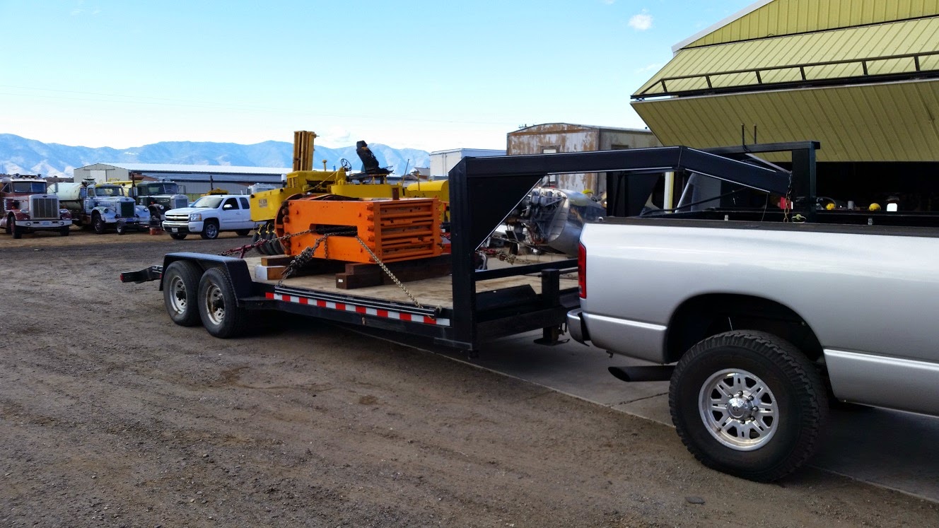
OK, so where to find one? Online! Where else? After months of searching, all I could find was one place near Cleveland, OH that had several of these presses for sale sitting out in the elements in a field. But, the cost was substantial. After more months of searching, I finally found a hit on Craigslist for someone that had one of these presses for sale that was fairly close to northern CA and was affordable. After a few phone calls and emails the sale was made and Prowler Aviation had acquired the "Go Big, Or Go Home" solution to pressing airplane parts.
These are the photos that were on Craigslist for this press:
.jpg)
.jpg)
.jpg)


Once I get this press moved inside the shop I will still have a lot of work to it. It will have to have a hydraulic unit designed and plumbed up to it. It will have to have the platens re-installed. It will have to have a box built to contain the rubber and have a "spacer" built to place the rubber box down lower off the top platen of the press. I will have to buy and install a large piece of steel that will become the "bolster" - which is what you place the die and part blank on before your run the hydraulics and shove it up into the rubber. It will end up looking something like this:

3. My Own New Band Saw Creation - Back several months ago when I was making several Prowler parts that are fabricated from 4130 steel I got an idea for making a better saw to cut these parts with. I already have two band saws in the shop, but they are not set up for cutting thin sheet steel (like .040", .050" and .063"). While I was making those parts, I just wanted to get the parts finished - but in the back of my mind I was "designing" a better tool to do that job.
I wanted a vertical metal cutting band saw with a blade that has a fairly high tooth count. The lowest cost solution is the Harbor Freight Horizontal/Vertical saw, but I already have a horizontal band saw for cutting larger steel rod and tubing. So, I considered finding one of these saws and removing the upper arm and designing a mount that would hold it permanently in the vertical position.
I didn't want to buy an entire new saw, just to toss out the lower 1/2 of the saw. So, I kept an eye out for one of these in used condition. Well, a few months ago I came by a free chance to try out my idea. Here it was as I originally got it (remember, it was free):
.jpg)
.jpg)
.jpg)
.jpg)
.jpg)


4. Builder Updates:
4.A. Francis and Robert - These fellows have really been moving along with their Prowler project. In the late summer (early fall) they finished assembling their spar. Since then they have begun to "decorate" the spar with all of the various brackets and parts that mount to it. Here is the aileron idler linkage and the spherical bearing (and bearing blocks) that support the MLG torque tube:
.jpg)
.jpg)
.jpg)
.jpg)
.jpg)
.JPG)
.JPG)
Find attached additional pictures of our project. The spars are now completed,
and we are starting working on positioning ribs and gear boxes. Francis has
installed a cabin with a small heater to go through winter … No bed yet :-))
Maybe a bed in the hangar explains why they are putting together their Prowler so quickly!!!
4.B. Bryan - I may have mentioned in a previous post that Bryan has had a non-work related injury that has left him on a prolonged disability for his job. Because of that, he has had a lot of time in the shop lately to work on his Prowler project. Therefore, his latest updates are pretty involved. So the easiest way for me to provide the update for Bryan and his Prowler is to let his update emails to me do all the talking:
From a Nov 3rd email:
Just to keep you in the loop, I believe I have finally figured out the hydraulic issue. I have a standard procedure set up to effectively bleed the system and it works quite well. I will copy you on that when I finalize the details.
Some of the heartache I was experiencing was due to the fact that on either side of the pump housing there are two spool valves behind large bolt head shaped caps. There is a seal there. When bench testing the unit everything would operate correctly, yet in the plane there were all kinds of issues. I believe I have finally tracked down the culprit in that the seal on one of those bolts was secure enough to handle the bench loads but when it had to draw fluid from the extend side to pressurize the retract side the load of the gear caused that seal to give way just enough to allow air back into the lines and the pump. I sat there and watched the pump make bubbles for the longest time before I came to this conclusion, but after pulling the pump and checking the seals the evidence suggested this air syphon theory. I have ordered the parts to rectify this issue but they have to come from the factory and that means 4 weeks or more wait time.
So.. in the mean time I have completed the windshield, built and installed the canopy, finished my drop tanks, riveted the left cockpit and empanage skin, labeled and installed the cockpit and instrument panel and re evaluated and rebuilt several systems to improve reliability and generally enhance the design.
I have Delta Hawk committed to delivering me a foam engine but they have not set a delivery date.
At the moment I am considering how best to work up the engine cowl. I believe that in the end I will have to extend the cowl to 56” verses the George design of 50” from firewall to the back of the spinner. That will manage my W&B issue and allow enough room to insert a 3” prop extension. The engine is 22” wide just a few inches back from the starter ring so I need some space (extension) to transition into the prop spinner interface. The PSRU did that for the automotive engine but I am direct drive. The big issue here is designing how best to attach the cowl to the engine mount and then divide it in sections for removal / inspection.
While I am waiting on the hydraulic parts and a foam engine, as I mentioned earlier, I have been methodically reviewing all the systems and structures on the aircraft and have redone, improved or modified as necessary. Today I did a complete redesign on my main stick assembly improving the attachment points, internal clearance for the pushrods and rod end bearings and of course doing more to lighten up that component without sacrificing any structural integrity.
From a Nov 24th update email:
I built (from scratch) my 3 jacks for the airplane gear swings etc. The drop tanks are done and attached to the wings, the canopy and windshield are on the airframe, I have finished the instrument panel and it is in, and now the biggest headache... only about 85% of all the electronics powered up without a squawk. Some issues are due to the way they interface and need to be awakened in sequence, others are due to unforeseen circumstances. For example, all my displays use a backlight sensor and automatically adjust for ambient light conditions. The O2 display does not. The instructions say it can be controlled with the display keys which come to find out work only when a rheostat power source is connected, that's the troublesome part. Without a rheo the power to the backlight pin starts the unit in night mode with associated limitations since it is sensing full voltage. That will start the apnea alarm and on and on...
The Dynon heated pitot is recalled and it took me half a day to extract it from the wing. Fortunately it was much easier to reach with the wing in the sling rather than on the plane.
My final punch list is down to just a few items. Hydraulic rebuild, avionics squawks, seat upholstery, and main wing fairings and a few other miscellaneous follow up items as I review the build. With those complete I will have a firewall aft ready airplane.
He didn't include any pictures with these updates, because, he is in that 75% complete and 75% to go phase of his project. While there is a lot of progress going on - there isn't too much that changes to the airplane visibly. The pictures that I posted in the last update are the most current that I have.
Awesome work and great progress Bryan! Thanks for the updates.
5. A Project For The Local EAA Chapter - I learned about a project that a gent (Bill) from the local EAA chapter was working on. Using all donated materials, time and labor, he has envisioned building a mobile, non-motion flight simulator that could be used to help generate interest in aviation at various EAA activities. In particular, he envisions using it at EAA Young Eagle events where the kids can sit in the simulator and "experience" the same flight in the simulator that they will see later in the real aircraft with the Young Eagle volunteers on their flights. It would also be able to be used as a free flight simulator using Microsoft Flight Sim or some similar software.
Well, after a little coordination, I got the project to my shop and got the ball rolling - so to speak. When I got the project it really consisted of a donated Beechcraft Bonanza hull and a donated boat trailer. Bill wanted the hull mounted rigidly to the trailer and hoped to have a catwalk installed along the right side of the hull. He also envisioned a set of steps at the back of the trailer for the kids to go up onto the trailer, and a set of steps at the front for them to exit after the sim ride.
Here is how the project looked when I picked it up. The Bonanza hull was just sitting on the boat trailer and strapped to the trailer with ratchet straps:


The picture above also shows my installation of an
expanded metal catwalk onto the boat trailer. I got about 2/3
of the catwalk installed before the rainy season hit the north
state. I haven't gotten a chance to finish it yet. Here
is another look at the catwalk along the right side of the hull:

Here is a right side profile shot:


6. Next Phase in the "Great Wall of Prowler" - If you've been watching my blogs for any length of time, you know that I have been on a seemingly unending quest to build more flat space around the front of my shop. Well, I have accomplished that, but now I need to take the next logical step to connect the road in front of the shop to the east end of the flat space that the house is on. To do this was going to take a lot of dirt.
A few months ago, the homeowners association needed some ditch work done on some of the roads in our development. Long story short, I got the dirt and the the HOA got some cleaned up ditches. That's a win-win! Here is the beginning of the "land bridge" from the corner of the shop:


That's all for this update. Thanks for stopping by to check in on our progress. Since this is the last update for 2014 - I will see you again, next year!
Happy Holidays!


