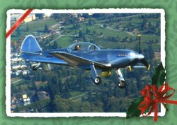
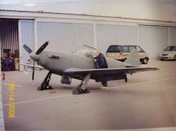
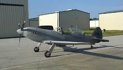
Thanks for stopping by to check in on Prowler Aviation. To say that this summer was a tough one would be an understatement. In June EZ had his engine failure and forced landing. Then, I came home from AirVenture to find the Carr Fire burning out of control in northern CA. A few days later I discovered that George had passed away. So, that is why it's taken me until now to get back to updating on some of the Prowler happenings over the summer.
I've recently written a blog post that is a tribute to George (see it here). And, I've also written up a blog update recently that re-caps EZ's harrowing experience and info on N611GM (see it here). So, the intent with this update is to go back and cover all the other things that were going on this summer while I was mostly dealing with these big items.
So, in this update I have:
1. Finishing More Parts for Kit #18
2. Builder Update
Francis - Excellent Progress Continues
Francis - Visit With Eric In Montreal
Ray - Update On MLG Torque Tube Problem
3. Work on the New FWF with Larry at AutoPSRU's
4. Update on Progress with N611GM Static Display5. AirVenture 2018
Before I move into the Prowler stuff, I wanted to share something that I witnessed recently that was pretty amazing. One night recently on a flight from JFK to LAX we suddenly saw this bright, funny looking light grow out of the horizon and climb in the western sky ahead of us. My First Officer saw it first:
It's not a great picture, but you get the idea. Looks kind-of like a comet, huh!?!? It was definitely nothing that either one of us had ever seen before. It was lit up very uniquely (can't really tell this from the photo) but, the sun was well down below the horizon ahead of us and it was a fairly dark night where we were. Yet, the sun was illuminating the cone of material that was sort-of pointed towards us.
Well, this "thing" was different enough that the center frequencies started perking up with calls from other aircraft that also saw this. Turns out it was a SpaceX rocket launch from somewhere near LA (maybe in the Mojave or over in Vandenberg - I'm not sure). But, it was really amazing to see from FL360. What was more amazing is that we were still over DEN!! Really!! We were headed west and just approaching the Rockies! To see something that large in the sky and still be 1/2 the continent away was really something different. Go SpaceX!! I have a kid who really wants to go to Mars someday! (More on that a little later).
Anyway, on with the Prowler update.
1. Finishing More Parts for Kit #18 - In previous blog updates I posted on fabricating the parts to make various sets of steel parts. Some of these included TW linkages, MLG torque tubes, sets of MLG hydraulic actuators and others. Most of these are some of the steel parts that I needed to make for Kit #18. While setting up to make these parts for Kit #18 I have also made 1-2 additional sets to have some spare parts in inventory and also have a set for one more additional kit that I might possibly assemble (sometime down the road).
Anyway, here are a few of those assemblies now that they are all welded, completed and ready to add to the boxes of parts for Kit #18. Here are two sets of stress mounts that fit into the 4 main fuselage longerons and face the aft side of the firewall at the motor mount positions. These transfer the propulsion forces (stresses) from the motor mounts into the fuselage skins via the 4 main longerons. They turned out really nice:
Here's 2 sets of flap actuators. These mount to the forward side of the rear spar and transfer the flap motor linear motion into movement of the wing flaps:Here's 2 sets of MLG torque tubes. These mount inside the torque boxes, pass through large spherical bearings mounted in the main wing spars and provide a place for the tops of the MLG struts to mount to (clamp to):
Here's a couple sets of the new style mounting brackets for the dead ends of the MLG hydraulic actuators. Bryan designed these to provide better angular matching to the motion of the hydraulic actuators and also incorporate the mounting brackets for the lower portions of the negative G mounts:
Here are 3 sets of the negative G brackets (upper portion) that mount to the cockpit fuselage bulkhead side formers. A 5/16" bolt passes from the upper bracket to the lower bracket and holds the fuselage to the wing spar in high negative G loads.
And, finally, 2 sets of TW actuating linkages:
I still have more parts to make for the TW systems, but I've gotten the more difficult ones knocked out for now. I'll update on the remaining parts in the next update.2. Builder Updates - Of course, the builder update that has dominated my world for the past several months has been EZ and his story (mentioned above and link above). Beyond this, the Prowler world continued to move on and I have some of their updates to share with you.
2.A. Francis - Excellent Progress Continues - Currently, Francis continues to be my most active builder (but, Eric might be a close second - see below). He has shared many pictures and notes with me as he goes about each successive part of the airplane that he is working on. Here, Francis has hinges laid out on the table to make his ailerons and flaps (He claims that the pink glasses are NOT his.....well, I don't know!?!? It looks like they might fit. Just sayin'!?!?):
Actually, he sent me this picture because he was having some misalignment between the trailing edges of the outboard flaps and the aileron. I checked with Ray and he had the same issue. So, by using a hinge with a slightly wider flange on each side, the hinge on the outboard flap and the hinge on the aileron could be aligned more closely (and still have enough room to rivet the forward hinge flange to the aft wing spar flange. If this doesn't make a lot of sense to you now - when you build the wing and you get to this point, then it will become clear!
Here, Francis has the left wing aileron (on the left) and the inboard flap section (on the right) laid end-to-end with the trailing edges resting against and aluminum angle (closest to front of picture). He has a single piece of hinge stock temporarily in place along the front edges (toward back of pic). If you look closely, you can see the junction between the two parts and the slight misalignment just behind the two clecos:
Another view from the other side:Here is his aileron assembly getting fitted for the stiffeners:
And, a top view looking down:
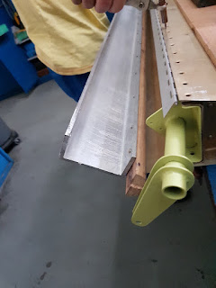
There have been almost as many ways devised to roll the leading edge of the flap and aileron skins as there have been Prowler builders (over the years). Here is how Francis rolled his. It looks like he found a good, hardwood, 1/2 round rod. Then, he screwed one flange of an aluminum channel to the flat side of the 1/2 round rod. I can't see in these pictures, but he must have somehow (maybe tape? or, maybe there is a small 90 deg flange bend on the skin?) affixed the leading edge of the aileron skin and/or flap skins to the joint between the aluminum angle flange and the 1/2 round rod. Then, he just rolled the aluminum channel and forced the skin to curl around the 1/2 round rod:
I'm not sure I ever asked George how he did this. But, I seem to think/remember that he just taped the leading edge of the skin to a piece of tubing about 1" in diamter and then just turned the tubing to curl the leading edge. Here is another view of the set up that Francis used:
Here are some fuel tank access panels that he is fabricating:
Very, very nice craftsmanship! I think that these are the access panels that will eventually hold the fuel level sensors on the inside of the forward wing fuel tanks:
More excellent work on the access panels, but it looks like something he was fabricating broke:
Here is one of those panels installed on the inboard wing rib:
Another view from the inside (note the steel clips that link the inboard and outboard flap segments together in the background):
Here are some of his nose ribs that make the boundaries of the fuel tanks in the leading edges of the outboard wings:
Notice the fuel tank sealant. In the email he sent me with these pictures, Francis wrote:
Hello Todd,
That's official, I hate the sealant!!😒
That stinks of the death🤢🤮!! After 2 days thats[it] still smell[s]!
In 5 minutes all the tools are sticky, and used 1 box of nitrile gloves😅
That's official, I hate the sealant!!😒
That stinks of the death🤢🤮!! After 2 days thats[it] still smell[s]!
In 5 minutes all the tools are sticky, and used 1 box of nitrile gloves😅
I have not had the pleasure of attempting this yet, myself. Now, I guess I'm not looking forward to this either!
As always, Francis, thank you very much for sending me all of your progress updates and pictures so that I can share them with the other Prowler builders!! I know the time it takes to do this and I really appreciate it (and I'm sure the other Prowler guys do as well). You are doing outstanding work and making excellent progress! We look forward to more, soon!
2.B. Francis - Visit With Eric In Montreal - Somehow, while doing all of his own Prowler work, Francis emailed me and told me that he was on vacation in the USA and wanted to try to go visit Eric in Montreal. I sent him the info to contact Eric and they did get an opportunity to meet. Here are some of the humorous email exchanges I had with Francis:
Hi Todd,
I work hard for[to] convince my girlfriend for[to] visit Montreal and meet Eric !!
Still 406 miles separates us! [But,] I am on good [the]way!!😁🤣🙂
[That is] If the wheel bearing of [this] Korean rental car permits it!
Our head and ears can [might] explode before [we get there]!!😎
And;
Hello Todd,
I am at the motel at[about] 1000 feet to[from] Eric's house!
(A very nice house and cars [out] front!)
I think I have to[should] shave and put [on] my better clothes!😁
He was not here [today?] but he reserved his Sunday for me!
Of course, I take a lot of pictures of his plane [for you].
later:
Before I meet Eric tomorrow he do[did] a low pass vertical [over] the motel with an RV with [the] smoke on 😎🤩😁👌👍
(I think I just figured out that Francis is a pretty funny & witty guy, but sometimes I miss a lot of it because it gets lost in the French-to-English translation!)
Anyway, Francis did meet with Eric! And, he did take several pictures that he sent me. Here are a few of them. Great craftsmanship here with the wing skin stiffeners in the radiator holes:
The wing joint area of the left wing. Those are the access plates and mounting plates for the fuel level sensors in the aft wing tanks:
First, what a beautiful job on the wing jig construction here. (Eric, after you are done with your wing building hold onto the wing jig. You will probably be able to sell it to another future Prowler builder. Nice job!) Also, excellent wing construction!
Very, very nice assembly of the main wing:
Those two long "ribs" on the top of the wing assembly are supports for the aft cockpit floor. They are flat along the top flange and curved to fit the bottom of the fuselage along the left hand flanges (as you look at them in this picture) [BTW - I need to make a set of those for my Kit #18 and that is one of the reasons I need to get my big "Orange Crush" press going.....soon.]
Excellent work, Eric!
After his meeting with Eric, Francis emailed me a few more times and sent me the pictures above. Here are some of his observations:
After his meeting with Eric, Francis emailed me a few more times and sent me the pictures above. Here are some of his observations:
We had a very, very, very good time with Eric!
He has a very good prowler kit (nice aluminum manufactured parts, straight and rigid (I am jealous)!
His work on his Prowler look good, he make the wing in is garage [at] home so he can work when[ever] he have some time. So he [is] progress[ing] rapidly!
He think[s] [he will] finish the plane in 3 years!
And, in a later email
Eric is a veritable work addict! He built his beautiful home. The furniture in his house [is] all home built (with out sofa), [also] 3/4 of his hangar, [and] a nice tricycle RV...
He offered to us a very good meal in his restaurant😋😃 (if you visit him try the "gibelotte" and "tarte au sucre"!) homemade by his very charming girlfriend.
I think HE is the faster Prowler builder (with out sacrificing build quality).
[Sidebar comment: I think the "without sofa" comment is Francis being witty again - meaning that he doesn't think that Eric ever sits around long enough to enjoy a sofa!]
It appears that Francis admits, in his own words, that he thinks that Eric is doing a better job, and building his Prowler faster! In any event, my complements to you both! You are BOTH doing an awesome job building your Prowlers. It is awesome to see Prowler builders getting together to share some information, a meal, and some fun!
Francis - Thank you very, very much for providing me with this information for the Prowler blog!
Eric - Outstanding job on your Prowler building! I agree with Francis - you are doing an excellent job! From the pictures he sent, you are a master aircraft builder!! Well done.
2.C. Ray - Update On MLG Torque Tube Problem - You may recall from a previous blog update that Ray and I were trying to cycle the MLG on his plane. We discovered a problem with the right MLG and deduced that there was something wrong inside the torque box where the pivot link attaches the end of the torque tube to the heavy steel channel built into it. Well, when he had time, Ray cut open access panels in the tops of his wings and was able to access the torque boxes through access panels that he had built into them during his wing construction. Here is his explanation of what he found:
The problem looks like it is caused by the rotation of the bearing as the gear retracts. When the gear is down the end of the shaft is with the bearing having very little rotation between the inner and outer races, almost flat. When the gear goes up the shaft rotates on the bearing enough that almost all of the angular movement of the bearing is used and the inner and outer race centerlines are about 20 deg apart, and the bearing is far enough out of a flat position that the part the bearing is pressed into can bind on the sleeve the mounting bolt goes through. This binding causes the bearing to move each time it goes up and can be seen by a zig zag line on the bearings outer race as it made it’s movement.
The fix was to put a sleeve over the mounting bolt sleeve to keep the bearing from sliding along the sleeve. I used a tube with a .634” ID to slide over the .625” bolt sleeve. The short part was cut to about .375, and the longer one was about .730”. I did have to belt sand a notch across both parts on one end about half way across and .090” deep to allow the spacer to not bind on the gear shaft when the gear was fully in the up position. After putting it all together, I cycled the shaft by hand several times and did find that the bearing moved to a neutral position where it didn’t bind and was happy.
Getting to the part is a pain since the wing skin has to be cut for an access panel, and if there was never a cutout in the landing gear torque box top that is an even larger problem.
OK, here's a few pictures to go with all that textual description. In the drawing below, I have highlighted the bearing that is the problem and the bolt that the assembly pivots on:
Here is a good picture of the assembly inside Ray's completed torque box on the left wing:
Here is the torque tube turned to the position it is in when the gear is down:
And, here it is turned to the position when the gear is up:
Now, as the gear cycles thru the 90 deg travel each time, that spherical bearing is going from where it's at the full limit of travel one way to the where the bearing nearly flat (sphere not rotated inside of the outer bearing race). When it was doing this, it (the bearing outer race) was constantly being wedged in its bore (in the pivot link) one way, then the "released' on the other way. What this did was allow the outer bearing race to "walk" out of the bore. This "walking" happened because the bearing wasn't pressed in tightly enough (the bore was slightly too large) and the pivot link was not staked well enough to prevent this from happening (staking a bearing is deforming the metal around the bore to prevent the bearing race from moving back out of the bore).
Ray's fix, for now (because it would be a lot of work to get the pivot links back out of the plane) was to simply put an appropriate sized spacer on each side of the bolt (and the wear sleeve) so that the bearing race could not move out of the bore in the pivot link. The last we talked, he had the airplane all back together with the exception of making the new access covers that he had to cut into the wing skins above the torque boxes. He's going to get to that soon.
Also, note the access panel that Ray had the foresight to build into the tops of his torque boxes. This was a great idea and saved him a lot of frustration in fixing this current issue. He (and I) recommends that everyone currently building their plane incorporate this mod into your builds. I will be making this standard on the kits that will be made in the future.
Thank you for the update on this issue! I'm glad you got it resolved without too much adversity. Also, Ray has decided to move out of Southern California. He has purchased a new home in Redmond, Oregon and is planning to start the moving process late this year and into next year. Congratulations Ray!
3. Work on the new Prowler FWF with Larry at AutoPSRU's - I stopped by to see Stuart and Larry again this year at their AutoPSRU's booth during AirVenture. Larry is making progress with the new Mustang style motor mount for the Prowler. Here is the latest picture I have from Larry of the new motor mount (that's a steel mock-up of a Prowler firewall on the left):
He was up to the point where I needed to send the AutoPSRU gearbox back that they let me borrow to check my FWF mock-up. He also needed to have a forward engine compartment bulkhead so that he could find a way to create a mounting point for it.
So, one day in Aug when I had some time I went down to the shed and took several measurements off of my mock-up with the AutoPSRU gearbox installed. [That way, I have some baseline measurements to work from.] Here are a few examples. The distance from the block to the final prop hub mounting flange:
This was a measurement to show Larry where the top of the forward engine compartment bulkhead should end up in relationship to a level off of the top, center of the firewall:
Then, I also clamped up a very ruff guess (using a slightly bent thin strip of wood) at where the engine compartment longerons will run so that Larry can get an idea of how much room there will be on each side of the engine at the front, middle and aft of the exhaust flange mounting surface. Here is the measure from the front/left corner of the exhaust manifold mounting surface to the left side engine compartment longeron outer surface (where the skins will be): Then, I removed the AutoPSRU gearbox from my FWF mock-up and set it up on the workbench with my somewhat crude (yellow) mock-up that I built several years ago. This allowed me to see how good of a job I did fabricating my gearbox mock-up. It's actually pretty good! Here's a side view:
Here's a back-to-back comparison:
I made several notes from these comparisons so that I could make a more accurate mock-up later on.
Later, I cooked up a "pseudo" forward engine compartment bulkhead (most of us refer to this part as the "horse collar" - for obvious reasons). I shipped this to Larry to use to design a
mounting point for it. I made it from pieces of flat aluminum sheet that I riveted
together. This mock-up horse collar only has 90 flanges, but it will work
well enough for now so that he can design a mounting system. [In production, this horse collar will be formed from a single piece of sheet and pressed in the big press I made. But, I don't have the press fully working yet - and I didn't want to hold Larry up. So, I just made one by hand that is a close approximation.] Here is a view of the aft side of the horse collar:
So, now Larry has the AutoPSRUs gearbox back and he received my horse collar. He's currently working on building this up on his Prowler FWF mock-up. Once he has this done, I will form some engine compartment longerons for him and he will be able to clamp them onto his mock-up. This will help ensure that the whole FWF will fit inside an engine compartment and (hopefully) will be as close as possible to the silhouette of the original production Prowler. More on this as it develops.
4. Update on Progress with N611GM Static Display - Since the last blog update I have made a little progress on making a static display from N611GM. After removing the engine in the last update, I needed to clean up the firewall and get everything off of it. This would allow me to mount a cage to the firewall to take the place of the engine. Here is a picture of the airplane as it sat after I got it off the trailer and set up next to my pumphouse:
In order to get the engine control cables off of the firewall, I had to get into the cockpit and disconnect all of the cables so that I could pull them through. Here is a picture of the cockpit as I began the process of digging into it and getting things cleaned up and disconnected [BTW - that's dried up sea weed in the foot wells!]:
Once I had the firewall cleaned off, I could start to make the cage that would replace the engine and gearbox and provide me something sturdy to mount the propeller blades to. To get started, I measured the original distance that the forward engine compartment bulkhead mounting brackets were located from the firewall (got these off the old engine mount). From that, I could begin rebuilding the engine compartment off the firewall. With enough of the engine compartment built back up, I could locate the forward bulkhead mounting brackets and then build up the "cage" to meet those brackets. Here is a pic of that in progress:
Eventually, I got all the individual pieces cut to size and tack welded together. Then, I took it all back apart and did a permanent weld to the cage. (I have a pile of this uni-strut material laying around that I got from an estate sale for super cheap, so I decided to use some of it up on this project) After getting the cage welded up, I mounted it back onto the firewall:
And, from the other side:
Eventually, I got the engine compartment rebuilt around the cage. With that done, I mounted the spinner backer directly off of the forward engine compartment bulkhead using some appropriately sized spacers. This allowed me to, finally, mount the spinner. Now, it was looking much better and getting closer. When it was all back together, it looked like this:
Now, it was time to turn to the prop blades. The first order of business was to get the blades off of the hub, so that I could straighten them. I had never taken anything like this apart before. It wasn't easy, but I managed to figure it out, eventually. Here is the hub and props before I started:
The first step was to remove the piston cylinder.
Here is the hub with the piston still mounted to the blades. The part in my hand is some kind of floating piston dampener (or travel limiter), I'm not sure:
I now know much more about how a controllable pitch prop works and how all the parts are connected, at least in a McCaulley prop design (Hartzell is much different. I saw the insides of one of those from a youTube vid).
With the blades removed, I then set up some blocks of wood in the 20 ton press and used them to straighten the prop blades. Here is one of them with pressure being applied to straighten it:
This was just a trial-and-error process where I would put pressure on a
spot (over bend it slightly) and then take the blade back out of the press and put a straight
edge on the back side of the blade. I would note where it needed a
little more pressure to straighten it a little more. Eventually, I got all 3 blades mostly straight again - at least good enough for a static display. Here they are all leaning on the work bench: At some point, they will need to be cleaned up and re-painted. But, for now, the focus was to get them mounted back on the static display.
With the blades straightened, it was now time to figure out how to mount them. I probably could have used the original hub, somehow. But, it was fairly heavy and only had mounting holes that would mount to the prop shaft - which is still attached to the engine and in the gearbox. I did not want to break apart the gearbox, so I looked for a different way. I went searching in the shop and I found a good heavy wall piece of tubing about 18 inches long. I figured that this would probably work OK. I would just need to adapt the blades to it. To do this, I put the tubing in the super spacer on the mill and cut 3 flat spots onto the end of the tubing at the proper angles:
With that done, I found some shaft that had a 1" diameter and cut it into 3 pieces. Then, I welded one of these pieces onto each flat spot on the tubing wall near the end. Here is what it looked like after I also welded a heavy washer to the end of the tube:
Next, I was going to have to find a way to adapt the new prop shaft style piece of tubing so that it would hold each prop blade securely. The ends of the props each had a 2.5" diameter hole/pocket in them like this:
But, the my new "prop shaft" has 1" diameter rods to hold the blades. So, a big bushing of some kind was in order. I jumped on the golf cart and headed down to the shed where I had stashed a bunch of steel and aluminum that I'd bought at an auction a few years back. Luckily, I found a piece of 6160 aluminum rod that would work perfect for this - and, it was already 2.5" on the O.D., so I didn't even need to turn them down to size! All I would need to do was clean up the outer surfaces and sand them down a bit to get them to fit. Here are the 3 pieces of bushing after I cut them each from the piece of stock I had:
After a little lathe work, I had the 3 bushings fitted into the prop blade roots and had some pilot holes drilled into them:
After a little more lathe work, I had each bushing fitting fully into the ends of the prop blades and got them fitted onto my new "prop shaft." Here is the assembly with 1 blade ready to mark the position of where I wanted to put a single hole and a counter sink to mount the blade:
At this point, I started to look the other direction from this new makeshift prop shaft that I was making. I had previously mounted the prop spinner backing plate to the forward engine compartment bulkhead. However, the prop spinner backer has a 5" diameter hole it it. But, my new makeshift prop shaft was only 1.5" in diameter. Time to make another bushing. I found a piece of round aluminum plate in my "misc aluminum drawer". After a little lathe work, here is the bushing test fitted into the prop spinner backing plate:
And, a close up of the hole and counter bore:
With these holes in the prop blade roots, I was able to position each blade onto the new prop shaft and mark the position where I needed to drill and tap a hole into the new prop shaft rods. Here is a pic where I am drilling the last of these holes (note the other 2 have already been tapped and have a 3/8" socket head cap screw in them):
With these holes all drilled and tapped in the correct places. The final step was to re-mount the new prop shaft tube into the static display and then weld it permanently onto the cage built inside of the engine compartment. Once the prop shaft was welded firmly into place, then I placed each blade onto it's prop shaft position and put the 3/8" socket head cap screw into the prop blade root and tightened them down snugly. With all 3 blades mounted, I put the prop spinner back on. Here is the net result:
Overall, I think it looks really good. So, now the static display is pretty much complete from the fire wall forward - except that the prop blades need to be re-painted. From here, I will continue to work from firewall and make my way aft as I fix things up.
My "yard art" definitely makes a much bigger "statement" with the FWF finished! Next, I'm going to work on the inner gear doors and begin to work on the inner and outer flap segments that got bent in the recovery. I'll keep you posted on the progress.
5. AirVenture 2018 - This year, AirVenture was a little different experience for me. After many years of staying off site and driving into AirVenture each day - I finally purchased a 5th wheel RV that I could use to stay on the grounds at Camp Scholler with the rest of the "gang" that I normally meet up with during the week. I actually have been looking for a rig for the past few years, but this past spring I finally found a rig that I really liked that was in my $$ range. Here is a pic of it and of the spots that I staked out for 3 of us this year (I got there on the Sat prior to the show and was the 1st one there):
The next day, Bryan showed up with his rig (on the right):
And, early Mon morning Dave & Laura joined us with their brand spankin' new rig (on the left):
We were all set up along a drainage ditch behind our rigs. It worked out very well - no neighbors directly behind us.
This was an interesting newcomer to AirVenture this year that I'd never seen before. I initially saw it flying from Camp Scholler (it was down over the N/S runway in "the box") and couldn't tell from that distance exactly what it was. It looked like I small P-38 from that vantage point. It wasn't until I took my first walk down the flight line that I figured it out! It's and interesting design. It's like a twin Extra with a jet engine mounted on the center-line. Isn't AirVenture cool!
Because I had extra room for people to stay with me this year, I invited a couple folks to join us (my 2 youngest daughters and I) this year. Here is Jen and Jordan checking out the HondaJet:
I met Jordan through my local EAA chapter. He went to school with my/our girls, he was heavily involved with our local CAP program and is pursuing a career in aviation. He won an EAA Air Academy scholarship in 2017 and really enjoyed it. This year, in 2018, he really wanted to go to AirVenture again, but didn't have a place to stay. I invited him to stay with us, and he (and his folks) accepted.
I met Jen on one of my flights in May. She is one of our Inflight crew members and told me that she was working as a flight attendant to fund her flight training to become a pilot. One day over breakfast I was talking about EAA and AirVenture. She'd never heard of it and was interested. So, I offered for her to also join us this year as well. After a bit of a frustrating experience (non-rev and space available) getting to OSH, she did join us and really enjoyed the AirVenture experience. Here are the 3 of us at the Brown Arch:
It was a pleasure having both of them with us this year. I enjoyed showing them the "ropes" of AirVenture and how to get around and see & do whatever appeals to them. They both really enjoyed the intense "everything aviation" experience that is AirVenture. It is awesome to see the interest and the enthusiasm that each of them has for aviation. My girls and I were really happy that we could help share the AirVenture experience with them. Jen emailed me recently and said she has already arranged vacation time for AirVenture 2019 and was working on arranging more "positive space" travel to and from the show next year. I think Jordan is going to try to make it back next year too, but he is in is first year of college and involved with the AFROTC program. So, he's not sure if his summer sked will allow it. I hope so - and you are both welcome join us again in 2019!
While I was walking the grounds showing Jen and Jordan around, we ran into a new Corsair that I'd not seen before. If you've been following my blog for any length of time, you know that I am an F-4U fan. It's my all-time favorite aircraft. Here is a pic of the "new guy":
Here is some history about this beautiful aircraft:
The airshows were awesome again - as always. Here is a pic of some of the "bomb drops" during the Wednesday Warbirds airshow:
On the last day for Jen and Jordan this year, we only had a few hours in the morning before they had to start their treks back to "real life." So, I figured that a couple of hours in the EAA museum might be a good fit. Plus, it'd been a while since I'd gone through it myself. The collection has grown a lot since my last time. Here's a shot of the main floor when you walk in:This picture really doesn't need description - suffice it to say, to have your own 50'x100' wall covered with your airplanes and awards in a museum would probably indicate that you've done some amazing things in your life! Burt Rutan's contribution to experimental aviation cannot (IMHO) ever be overstated! If you just (only) considered the Voyager project - that, in and of itself, was an almost unbelievable feat and an incredible story! This is a well-deserved tribute to both Burt & Dick Rutan:
Once again, the Wed night airshow got rained out. Actually, this year they cancelled it before
everyone headed down to the flight line (due to an advancing storm front). The night airshow got rescheduled for Thurs night, and it was impressive, as always. The closing fireworks is always amazing:
I think the fireworks that EAA puts on after the night airshow is consistently the best fireworks show that I've ever seen. It is loud, long,
and intense all the way until...... you know..... what happens at the end:
Here are our two youngest daughters in front of another one of my favorite airplanes:
And, the girls near Boeing Plaza with the C17 in the background:Our middle daughter is really interested in NASA and travel to Mars. So, guess who spent a lot of time in this tent!?!?!
The girls participated again this year in the EAA program called Women Soar, You Soar (WSYS). It is such a great program!! If you have a high school aged girl that is interested in anything related to aviation, please check it out. This year, the youngest daughter got a Grumman Goose ride at the Seaplane Base:
As you can see, this year's AirVenture was less about me and Prowler Aviation and more about offering and sharing the experience with others. It was a great show, and we are all counting down the days until AirVenture 2019!
That's a wrap for this update. I hope to have some time in the shop this fall and get some more parts made for Kit #18. I would also like to get the big hydraulic press plumbing tweaked and leaks fixed up and then get some parts made with it. Have a great fall season, everyone!


