In any event, I will endeavor to recap the highlights of my Prowler related activities. Here's the list of Prowler related stuff:
1. Ray's Prowler Progress
2. Bryan's Prowler Progress
3. Francis' & Robert's Prowler Progress
4. Cleaning Out Chuck's Hangar
5. Helping George Get His Airplane on Video
6. Rebuilding a Backup Generator
Then, here's a few items that are not directly related to Prowler:
1. Retaining Wall
2. Shop Heater
3. Helping A Buddy Rebuild a CNC Mill
4. Helping Another Buddy with a Yoder Power Hammer Redux
PROWLER ITEMS
1. Ray's Prowler Progress - It has been so long since my last update that there are several "phases" of Ray's recent work to review. I'll basically break it into 3 parts: 1) Engine Runs; 2) Engine Run Squawks & Fixes; and 3) Paint Prep and Paint.
1) Engine Runs: I put a couple of initial engine run videos in the previous blog update. During that set of engine runs Ray was experiencing low idle control issues with the engine. The fix was sending the fuel injection control (mechanical computer) in for a factory reset and "tweaking." It just so happened that a former AFP tech rep lived just a few miles from Ray. Warren is a great guy and pretty quickly diagnosed the issue. Here's a video of the engine near idle after the fuel control was tweaked and re-installed:
With the engine control much improved, the goal was to run the engine a little more aggressively to get it to heat up and check all the oil, water, fuel and electrical parameters. Here's a higher power run from the other angle. The sound changes are from Ray feathering the prop and changing speeds with the prop feathered and un-feathered:
Squawks & Fixes - Ray discovered a few gripes during the run ups. One was an ignition timing problem. After some research and messing around it turned out that the ignition timing problems were being caused by a couple things going on. First, was the timing advance and retard system. The system was originally set up with the timing locked with a lot of (too much) advance. Ray now has it set up for 5 degrees of retard for engine start, then as the rpm climbs the timing advances to 27-28 degrees advance at around 1500 rpm. The second issue was that one distributor was not holding it's timing setting very well. Turns out that one of the distributors was missing a bushing that no one knew about. After buying a rebuild kit for both distributors Ray found that both rebuild kits came with this bushing - but the one distributor never had it installed. So, that corrected the problem.
The last main squawk was that Ray noticed that the prop tips were not tracking correctly (in the same plane) all the time. After a quick tear down, we found something interesting. What you see in the next pic is the prop flange, prop nut, and retainer that holds the prop hub to the PSRU (gearbox). The prop flange has the outer hole pattern in it and it is splined on the inside diameter. It slips onto the matching o.d. spline on the prop shaft in the center (prop shaft has the center hole to allow prop governor oil to the prop hub). The prop shaft is threaded on the o.d. near the end. The splines cannot be seen in the first picture because they are hidden behind the round prop nut. The prop nut is the circular part with all of the small holes in the edge facing the camera. It is threaded on the i.d. and smooth on the o.d. On the far side of the prop nut (opposite the end with all the small holes), it is flat and pushes against a shoulder that is machined into prop hub. The prop nut retainer is the piece in Ray's hand. Here it is:


The problem that Ray was having was that the retainer was not staying in place. It was working its way forward and the pins were coming out of the aligned pin holes. After a few minutes of looking this over, I discovered something. The hole in the retainer is much smaller than the hole in the prop shaft. What was causing the retainer to push forward was the rush of oil from the prop governor to the prop hub (since the hole in the retainer was much smaller and causing a restriction). This restriction was enough to cause a pressure to develop on the "edge" that was sticking out into the oil flow and blowing the retainer out of the pin holes.
The fix was a two part process. First, we drilled the hole in the center of the retainer out to the same size as the hole in the prop shaft. Then, as an added measure of protection, Ray had the inside edge of the prop hub machined with a narrow slot to allow for using a inside snap ring to also prevent the retainer from being pushed out of the pin holes.
Once Ray got the plane running well and most of the issues corrected, it was time to start prepping the airplane for paint. He moved it to a undisclosed location for final painting. Painting anything in the "great" state of CA is insanely regulated. So, to that end, Ray is (rightfully) trying to fly under the radar on this part of the project. I will let Ray tell you the status in an email he sent to me on 4/30/13:
Don’t paint your aircraft in CA. Biggest PITA
ever. Get the painting done somewhere else and hide out until it’s done. The painting is incredibly
time consuming because of the CA nonsense, save the whales, you know.
The fuselage was finished for the color and clear coat, the
stuff that protects the CA spec paint from the elements, was done last week.
Several days were lost to weather, its been cool and damp. The CA paint will blush the clear
coat if not warmer and lower humidity. We forgot to get the gloss clear coat
for the insignias, and the painter is on a 4 day trip - so no painting till
Friday. If you don’t clear coat right after the color coat the layers may not
chemically bond. After the insignias go on it will come out of the paint room
he built and the final color sanding and detail clean up will be done. The
wings and tail will then go into the paint room and I will start putting
antennas, prop and like things on the fuselage
Ray
Thanks for the update Ray, we can't wait to see the new paint job.
2. Bryan's Prowler Progress - One of the items that I brought back on the trip to help clean out Chuck's hangar (discussed below) was a spare canopy that Chuck had acquired. Bryan bought that canopy from Nancy and I picked it up for Bryan when I was there. Once back in the shop, I set out to pack it up for shipping to Bryan. I kept the box that my drill press had come in when I bought it several years ago. Turns out, it was a pretty good fit:


Here is a recent update Bryan sent me just a few days ago:
Well, I am in the doldrums phase of construction where you work 16 hours a day on the airplane for an entire week and look back and see little change from the week before - that is unless you look to see the details. That's what next month will be all about also.
I have built and pre-installed my avionics rack, the canopy frame, its lifting mechanism, exterior and interior latching mechanisms, the fuel selector , throttle quadrant, headphone jacks, 0'2 system component locations, control stick wiring, seat belts, instrument panel and all it's attachments and supports etc.
Like I mentioned earlier the bad news was cracking the canopy and having to re-plumb the hydraulic system. I have another canopy custom built for the aircraft on order and have finished re routing all the hydraulic, pitot and static lines for my ADHRS systems.
Here are a few pictures of the details...
The avionics panel initial layout:


The small red handle you see at the bottom of the glove box is the emergency gear up-latch release handle (after modifying the up-locks to emergency release via cable pull):

Bryan
Since that email, Bryan sent me a link to a piece of video of the SR22 running with the DeltaHawk Diesel engine Here it is: Cirrus First Run-Up with DeltaHawk Diesel Engine
Thanks for the great update Bryan. Really nice work!
3. Francis' & Robert's Prowler Progress - Since my last blog update, Francis and Robert have begun the process of de-riveting their spar so that they can do the chromate conversion process (Alodining) to all of the spar pieces. The original owner put the spar together before completing this. While it is not an absolute requirement, studies and various data have show that aluminum parts that have a chromate conversion process done to them before painting have an increases the life span of the parts by about 1/3 (before inevitable and irreversible corrosion sets in). So, it is worth the extra effort.
While de-riveting the spar, they have also been building the wing jig and here are a few shots of the spar temporarily installed in the jig:
+1.jpg)
.jpg)
.jpg)
.jpg)
.jpg)
.jpg)
.jpg)
4. Cleaning Out Chuck's Hangar -I don't have any pictures, unfortunately, from the trip to help Nancy clean out Chuck's hangar (so that she could turn it back over to the city). I drove down to Salinas (from Sacramento) after commuting home from work on the last week in Jan. It was a whirl-wind trip, but between Ray, his wife Isabel, Nancy and I we got a large trailer load delivered to her home garage by 1100pm on that first day.
The next day, we got an early start and finished cleaning almost everything out of the hangar - with the help of many folks with nearby hangars. By 6pm on the second day Ray and I had loaded up all of the things that we were buying from Nancy and on our way out of town. I ended up with an entire pickup truck and 16' trailer load of "stuff." It took the better part of the whole month of Feb (on my days off) to sort thru all the boxes and boxes of stuff from Chuck's hangar.
In the end, it was a sad occasion, but we all made the best of it. And, Ray and I ended up buying some great items from Nancy and she was able to turn the hangar back over to the city - all cleaned out so the city would not charge any extra fees.
5. Helping George Get His Airplane on Video -
George contacted me a couple of times this spring to help him get some film of his airplane in a high speed taxi. Apparently, one of the online aircraft-for-sale sites had a deal going for classified ads that included text, pictures and video. So, we spent a few mornings at the RBL airport firing up the airplane and shooting some video. Here are a few pix from one morning:


6. Rebuilding a Backup Generator - In my last update I showed a picture of this genset that I had purchased from buddy:

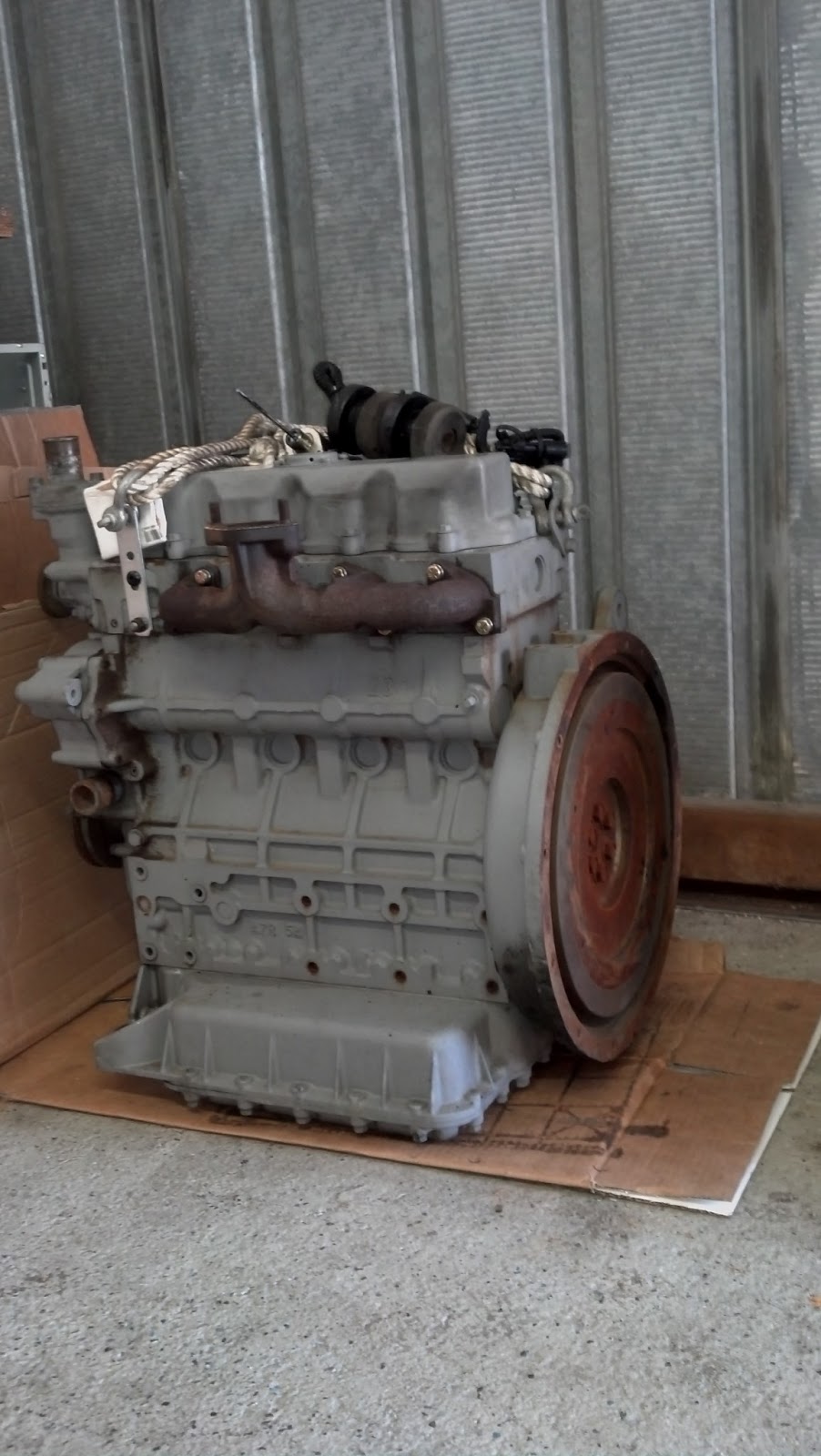
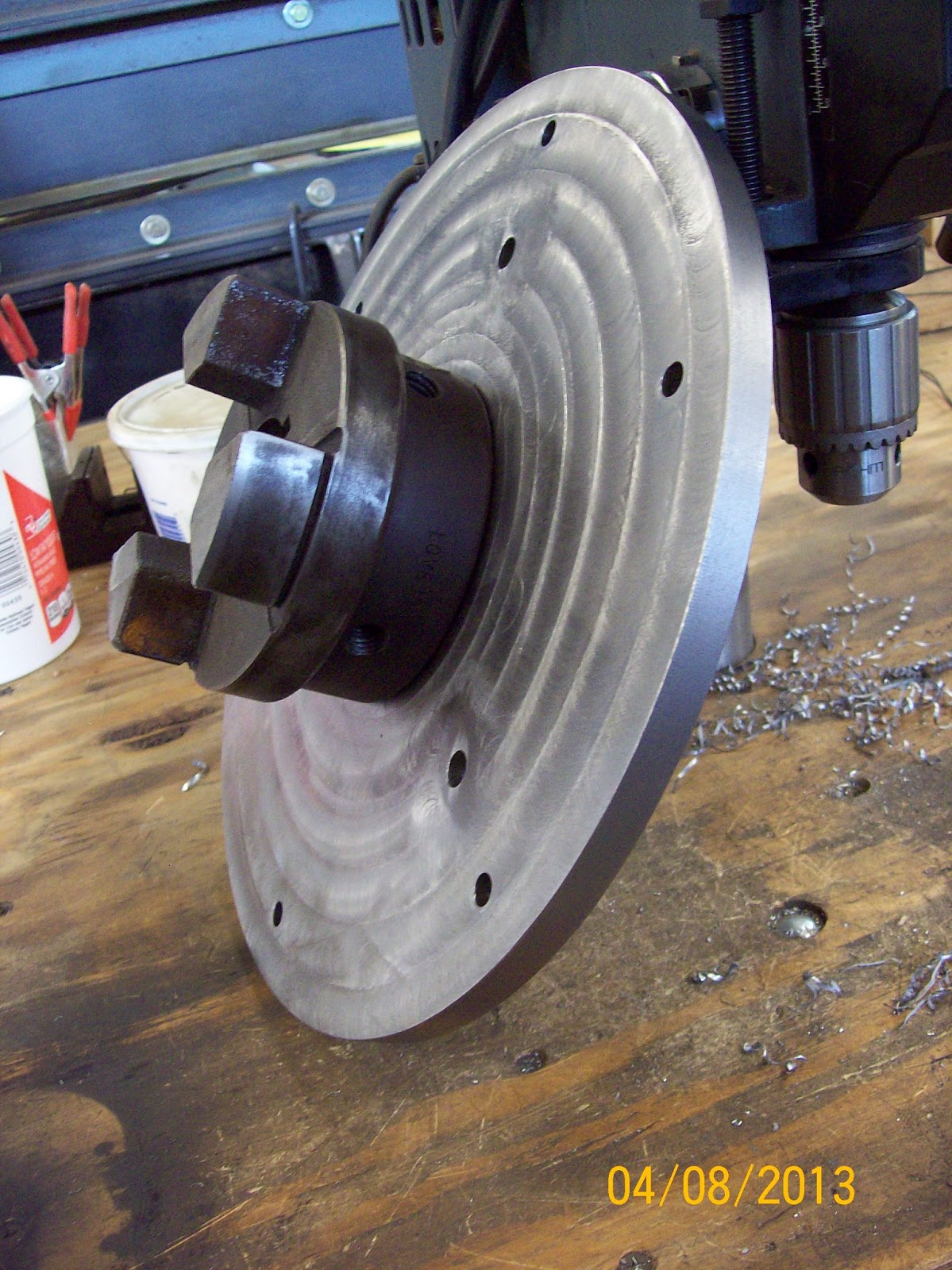
In order to adapt this engine to connect to the generator I was going to have to make a plate to bolt to the flywheel you see in the pic above. There was a 6 bolt hole pattern that I could use to bolt a plate directly to the flywheel and then to that same plate I could bolt 1/2 of the Lovejoy coupling already installed on the generator. So, first I had to find a plate and drill the hole pattern into it with the Bridgeport Mill:

Here you can see the 3 counter-sunk bolts holding the plate to the rotary table while machining the plate to round:


NON-PROWLER ITEMS
1. Retaining Wall - Since buying an RV to take the family trip last summer, I've been wanting to extend my big retaining wall in front of the shop (affectionately known by now as the "Great Wall of Prowler"). This extension will allow me to have a convenient, yet out-of-the-way place to park the RV when not in use (and get it out of the main driveway). I got started on this project early this spring for two main reasons. First, because the weather turned dry really early this year (it's gonna be a bad wild fire season!). Second, I got access to A LOT of broken concrete pieces (10 trailer loads full) about the same time. Here's a couple of pix of the wall building progress:


2. Shop Heater - Several years ago I got a deal on a shop heater and a propane bottle. At some point I hung the heater off the ceiling on the south end of the shop - mostly just to get it up off the floor and out of the way.

This particular furnace is a Dayton brand from Grainger. A quick call to them yielded the nat gas to LP conversions kit for the tidy sum of around $300. Well, that may be a "competitive" price to some, but not from me. So, I once again hit the Internet for some research. The main burner jets are brass and thread directly into sockets that are welded to the main steel line that you see behind these burner assemblies:


So, now I have the furnace converted for LP gas. Next on the list is plumbing the LP gas to the furnace. I've rounded up another 100lbs LP tank (two total), a regulator valve for the tanks and some copper piping (all free). Once the gas is plumbed to the furnace I will have to do some test burns to set the air shutters on all of the burner assemblies. Before I can do that though, I have to have the exhaust vent put in up through the ceiling, attic and roof. I've found most of the vent kit that I will need to install. I just have to find 2 more 3foot straight sections of B-vent pipe and the time to tackle putting in a roof jack for the vent pipe.
So, while getting these items rounded up, and in the midst of working the day job, and while tackling other pop up projects, it turned warm again and now I don't need the heat. So, the priority of this project has fallen a bit. I will, however, try to get it done sometime this summer/fall - before I need the heat again next winter. More on this later.
3. Helping A Buddy Rebuild a CNC Mill - I also have another friend that is in the ammunition reloading business. He makes several dies, presses and press accessories for the ammo reloading community. For one set of these parts he needs to have a 3 axis CNC mill. Well, he found one in pretty good condition that was not quite operational:


I decided to delve into the old controller to see what I could find out. Heck, after all, I had to prove that mom & dad didn't spend all that money for my electrical engineering degree for nothing - right!! To make a long story as short as possible, we got very lucky and found a company that had just replaced an old 8025 control in one of their machines and it was supposedly in "good working condition." Well, we got this used control and I swapped around some cards and found that "good working condition" can be a subjective thing - I guess. Because, there were several cards in the new-used control that were not working either.
Finally, after a lot of troubleshooting, and testing I was able to make one working controller out of the two that were not. So, in the end, we got the 8025 control working again for around $800 instead of $8K. A good deal, I guess, but still an expensive mistake. Lessons learned and enough said.
This mill had originally been built with a totally different CNC control system on it. At some point, someone did a retro-fit and installed the F8025 controller that it now has. When they did this, they used part of the old system that ran the main spindle motor (a 3 hp, 3phase, 220Vac motor). The machine did not have a VFD (Variable Frequency Drive) installed to control the spindle motor. Instead it used a system or relays and a mechanical speed control system. Almost all new machines now use VFD's to control spindle motion. It is pretty simple task to get the F8025 to control the spindle when using a VFD, but for some reason they left a more complex "old school" spindle control with the retro-fit. Pat knew this and had already bought a new VFD to use to control the spindle motor.
Before continuing any more work on the mill though, Pat wanted to run the spindle to make sure that it was in good shape and it would not be a waste of time and money to keep working on the machine (only to find out later that the spindle was shot). So, I used his new VFD and wired up a control board to hook up to the mill to test the spindle. Here is the test board wired to a 5hp motor I had laying around the shop:

4. Helping Another Buddy with a Yoder Power Hammer Redux - I have another friend that is a phenomenal sheetmetal guy and welder. If you are in the sheetmetal fabrication business, the tool to have is a Yoder Power Hammer. These things are old school. They were fabricated from huge castings in the early 1900's and they are no longer produced in any quantity that will allow one to be had for a price that anyone can afford. Those that have them, keep them and pass them down to their apprentices or others in the business. If one (rarely) comes up for sale it is most likely because it is run-out and thrashed - and then they still want a small fortune for it. This is what an original Yoder looks like:


My buddy approached me about doing the CAD work for one of these so that he could use the drawings to have parts fabricated for a knock-off copy. He was able to obtain copies of original Yoder drawings and a lot of info on other copies of the machine that many others have attempted. Never being the one to turn down a challenge, I agreed and we are working our way thru the project. My first effort was to duplicate the machine in my CAD software and create a 2D, 2-view drawing:


Well, that's it for this update. It's taken me a week (it's now May 7th) to collect some info, import pictures, write the update and proof read and correct, etc. These updates can be as time consuming as the projects that I am writing about. But, I hope that it is informational and maybe even helpful to others that are working on similar projects. I will, once again, try to step up the frequency of my updates so that they are not so long and involved. Take care for now, and thanks for stopping by.


.png)