1. 100Ton Press Repairs
2. Work On "Kit #18"
3. Parts For Kit #6
4. Builder Updates
4.A. Ray
4. B. Bryan
4.C. Francis & Robert
5. Prowler Sheet Metal Shear
6. Lathe Enclosure
7. New Door On Sandblast Cabinet
8. Generator Test
9. Yoder Power Hammer Progress
10. Next Moves
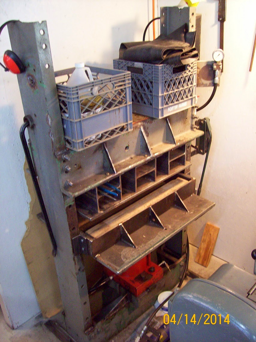
1. 100Ton Press Repairs - During the initial tests in using the press to form parts, I discovered that the process was essentially working (covered this in the previous post). The bad news was, I had bent the press's upper H frame that holds the "lid" to the box that contains the rubber when pressing a part. With the center of the lid humped up almost 3/16" - any attempts to bend a long part might cause the part to not be formed over the die completely. So, I needed to repair the press and then "beef it up" so that it would not continue to bend while forming parts. This was going to be a perfect project for dad and I to work on together during my parents annual spring visit to see the grandkids.
The first step was to remove everything off of the top of the press and then remove the lid and spacers from the upper H frame. The lid and spacers are welded together as one unit and it was easily straightened in the press by flipping it over and putting shims in the proper places.
Next, we headed off to the local surplus steel place to find some "beef." We picked out two pieces of 3/4" thick x 6" wide steel flat bar to scab onto the inside of the upper H frame angles. We decided to forgo trying to straighten the two angle irons and just leave them bent. It would have been a lot of extra work and might have introduced more alignment issues when trying to put it all back together. Here's a pic:

.JPG)
.JPG)

2. Work On "Kit #18" - The kit that I picked up just after the new year from Salinas, CA has been the focus of most of my attention lately. I've added it to my "kit list" spreadsheet that I use to track all of the Prowler kits (owners, contact info, status, etc). This kit has been given the serial number of "Kit #18." I have been going thru each of the parts and inventorying everything and dividing them up into the respective sub-kit sections. Also, while going thru all the parts (sub-kit by sub-kit), I have been going thru my old inventory from George to see if I have any of the needed missing parts. If so, I'm adding it to the kit. Then, where missing parts are fairly simple and easy to fabricate, I have been making many of these simpler parts. Keep in mind, however, that these are hand-formed parts that I am making from the patterns that I got from George - just the way that he made them back in the day.
Here are some pics of the sub-kits bundled and setting around my office (no room left in the shop!). This is fuselage parts and firewall on the right (over exposed by the sun):


Main landing gear struts and cockpit framing components on left:

3. Parts For Kit #6 - Once Bryan got a chance to inventory the kit that he and I picked up just before Christmas, he sent me a list of parts that was missing. Here's a pic of most of the parts that I fabricated to finish out this kit:


4. Builder Updates
4.A. Ray Prowler Progress - Ray is in the process of going thru all of his airplane again, system by system, getting as many bugs and gottcha's taken care of as possible before his 1st flight. Recently Ray was going over the tailwheel compartment and called to tell me that while he was working on his tailwheel, he noticed that as he moved the tailwheel slightly the MLG inner doors would move up/down a little. After some investigation he concluded that the MLG inner door sequencing valves were bypassing hydraulic fluid when they should have been closed. Here's a pic that shows the position of the sequence valve:

The latest report from Ray is that he has found some fuel leaks in the wings. It looks like he will have to remove the wings and slosh the tanks to get the drips stopped. The good news is (in Ray's words):
"So far the design works, everything seemed to flow where it was supposed to go from the tank to the engine feed line. I could fill the Aux tank from the leading edge tanks with no problems. The check valves in the fuel feed lines do not seem to reduce the flow of fuel from the tanks, and the vent check valves at the wing tips prevent reverse flow when blowing air from the vacuum cleaner into the tank. When draining the tank from the drain fitting just past the fuel pump it will drain at about 5 min per gal from the forward tank by gravity alone. The Aux tank can be emptied completely by pressurizing the Aux tank vent line and blowing the fuel out the drain fitting.. Aside from the pump thing and the one leak the fuel system design looks like it will get the job done."
Hopefully, the tank sealing will go well and that will take care of the fuel system issues. Ray also indicated that he has a medical issue that will cause some of the Prowler work (and 1st flight) to move to the right for a while. Here's another pic from Ray's airplane reveal of his new paint job earlier this year:

4. B. Bryan's Prowler Progress - Bryan has been out on "medical" lately while he has had Lasik done on his eyes by the best doctor on the planet (in Europe). Then, in an strange turn of events, he made it all the way back to the States after successful eye surgery - only to get injured while pushing his airport car out of it's parking spot to give it a jump start! As Bryan states:
"We are back! However, when I got to the crew lot after jump seating from STN i had to push my car and ruptured all the tendons in my right foot. I am now confined to a wheel chair and can not walk. Dr. says 2 months in the chair to start."
Whoa! Sorry to hear that Bryan. That's a major bummer. In a recent follow-up Bryan said:
"I have gotten through the high risk area with flying colors. No ill effects, infections or issues with wound healing. However... now with a hard cast bolted on I am still under the order to not use the foot for anything. Can't put any weight, walk, stand or dance on it. At best I can use my toes for limited tasks like touching the channel changer on the remote. So, another month of this and then I should start with some reasonable mobility. I have the promise that when this is all over I will be as good as new!"
It's great to hear that the recovery is starting out well and that recovery should be 100%. Bryan also reports that he's using this down time to clean up all of his Prowler documentation and begin writing his Aircraft Flight Manual (AFM). I guess life is all about "making lemonade."
Well, before Bryan left to have his Lasik procedure done, he managed to go get a bunch of lumber and OSB sheathing and made crates for all of the Kit #6 parts that we recovered late last year. By the looks of the pictures he sent me, he did an awesome job. Here is Kit #6 in crates for shipping to a future buyer. This is obviously the MLG:


This looks like the crate of longer and larger formed aluminum parts:


4.C. Francis & Robert - I have gotten a few emails from Francis in France with update pictures on their progress on the French Prowler. In a previous blog I showed the MLG HCAB that Francis was welding up. Here they are completed and painted:


Here are a couple of shots of their outboard wing spars after they have been alodined and cleco'ed together.


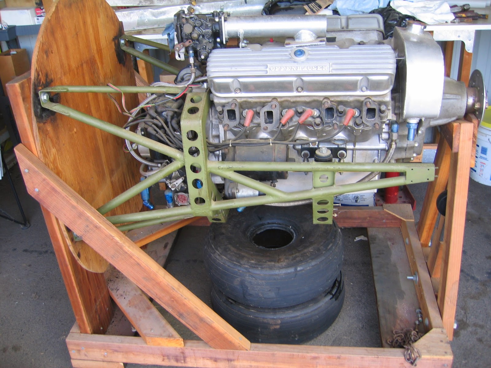
Francis and Robert are also doing some initial research on the engine that they have for their Prowler. It is one of George's original Auto Aviation engines from the 1980's. George had sold almost 30 of these auto conversion engines using the old Oldsmobile F-85 aluminum block engine (and his proprietary reduction gear and accessories gear drive). I showed these to George a few weeks ago and he could not tell precisely which engine this was, or what airplane it went on after he sold it. He did say that this was not one of his motor mounts. Someone had must have had it made for another application. Here are a few pix:


http://www.prowleraviation.com/contact/contact.html
Excellent work guys! You are progressing very quickly. It looks great! Francis, thank you for the frequent updates and information to share here on the Prowler Blog.
5. Prowler Sheet Metal Shear - Earlier this year I purchased a used Pexto 52" gap shear (actually got it when I picked up the partial kit in Salinas, CA). Like most Prowler equipment I purchase, it needs a little TLC, but it should work fine. This exact same shear is still available, brand new, from Roper Whitney for the cool sum of $16K.
http://www.roperwhitney.com/foot-squaring-shears.html
Obviously. being used, I didn't pay anything near that. But, this is still a very valuable tool for cutting airplane parts, because it is a gap shear:


6. Lathe Enclosure - Years ago I took apart an large air handling/filter unit that had a 5hp 3phase motor in it that I wanted to scavenge for a rotary phase converter that I was building. The guy that I got it from told me that he would only sell the motor if I took the entire enclosure with it. Part of the filter housing was almost the perfect shape to make a back-splash guard for my lathe. When dad was in the shop in April we finished making a few required mod's and painted the housing:

.JPG)
7. New Door On Sandblast Cabinet - One of the things I got from Chuck's hangar a few years ago was his old, small sandblast cabinet. It's not too big, but really handy to clean up small parts. And, it doesn't take up too much space in the shop. But, the old top did not have a rail around the edges of the Plexiglas and the glass was old and the corners rolled up. So, the top loading door/glass leaked dust out pretty bad. Also, the florescent light was not working. So, dad and I made up a new frame and mounted new glass for the new top loading door:
.JPG)
.JPG)
8. Generator Progress & Test - I got motivated this spring to try to get some of my many projects that have been "hanging fire" move into the "completed" category. The back-up diesel generator was one of these. This project has been waiting for me to solve how I was going to handle the alternator for the Kubota engine that runs this generator. Like in most engine designs, the alternator is used to (obviously) charge the battery and it also serves as the belt tensioner of the one belt that drives the alternator and the coolant pump (off of the crankshaft).
Well, in this application I really didn't need an alternator. During periods when the engine is not running, the battery can be topped off by a battery charger. Also, as soon as this engine starts it automatically begins generating electricity from the 15kW generator attached to the crankshaft. That can also be used to power a battery charger and replenish the battery charge. So, I decided to fabricate an idler pulley that used the same mounting system as the alternator and use that to take the place of an alternator. I started with a 1/2" steel plate in a triangular shape. Then, I added the L shaped bracket to place over the original alternator hinge point on the engine case. You can see it here:


Now, the only remaining work on this system is to add two protection circuits. I have to add a LOW oil pressure switch and HIGH water temp switch that will each activate the fuel shut-down relay in case of a failure of each. This is the minimum requirement to protect a genset to keep the system safe in case of oil pressure failure or coolant failure. I hope to get that done sometime this summer.
9. Yoder Power Hammer Progress - You might recall that I was helping a buddy do the CAD work to build a Yoder inspired power hammer of his own design. A few months ago he called to see if I wanted to go up to the shop that is building this machine and see the progress on it. So we met for lunch and then went to see the machine. Here is a picture of the gang (Max's son Koby on left, Max, and Keith in front) inspecting the progress:


10. Next Moves - Here's a punch list of items to get done in the shop arranged from highest priority on down:
1. Find a suitable block of rubber for the Rib Smasher Press
2. Cut the dies for the new style tip ribs for the 1st New Prowler production airplane;
3. Form the tip ribs and fit them onto my wing spar and wing jig;
4. If these new tip ribs turn out OK , then make dies and press nose ribs for Francis and Robert;
5. Get the diesel genset finished with the protection systems and get it out of the shop;
6. Get the Pexto shear on casters and get it working for cutting airplane parts;
7. Find new homes for 1 (or possibly 2) second had kits that Bryan and I have.
8. Squeeze in time for a week at AirVenture ;-)
Thanks for stopping by to check on the progress here at the New Prowler Aviation. I know things seem to move at a glacial pace around here at times. But, I'm always working on something related to Prowler (nearly every single day) and I am trying to support the current builders in any way that I can or is needed. Please send feedback if you have any thoughts, concerns or suggestions.
http://www.prowleraviation.com/contact/contact.html
Have a great summer!


