Hello Again Everyone,
Welcome back to the Prowler blog. Well, it's Nov and I haven't done an update since May. Where do the months go so quickly!?!?
In this update:
1. Press pad for 400 Ton Press
2. The Big Shop Equipment Shuffle
3. Fabricating 4 MLG Torque Tubes
4. Builder Updates:
4.A. Ray
4.B. Francis
4.C. Ernest
5. EAA AirVenture 2017 Recap
Part of the reason that I haven't gotten much Prowler work done lately is that I've been out of action for a few months due to a knee surgery. Sometime in late June and early July my knee started tweaking me. After X-rays, an MRI and a few visits to the orthopedic doc - we determined that I needed arthroscopic surgery to fix a lateral meniscus tear in my right knee. Surgery was sked for Sep 6th and once the doc got a look inside my knee, the tear was more serious and in a more serious place than what any of the indications were. Turns out, I had a near complete delamination of my meniscus in the front, center area of my knee.
The good news is (now) that I seem to be headed to 100% chance of full long term recovery; the bad news is/was I had to spend 6 weeks with no weight on my knee. A month and a half of literally sitting around and only walking with crutches was nearly intolerable for me! I've never been that unproductive in my entire life! I've been walking again now for almost 3 weeks and I'm starting to get back to being productive again. Looks like I've got 2-3 weeks of PT remaining and then I'll be headed back to work in late Nov or early Dec - but until then I hope to get some Prowler projects completed.
I did manage to get some Prowler work accomplished the week before my surgery, and that is in this update. I also have quite a few builder updates. There are several owners and builders that are really busy and making good progress. Here are the details:
1. Press pad for 400 Ton Press - Since the new 400 ton press has been working for several months, I finally got busy and sourced a rubber pad for it. It's actually not rubber, but a type of polyurethane that is specifically formulated for using in forming operations using the Guerin and Wheelon processes. I sent several RFQ's to various press pad manufacturers and finally decided to go with the
Kastalon Company and their product that they call
Gummilast.
I spent more on this one piece of polyurethane than I did for the original purchase of the press!! But, I figured that I spent the time and money to completely rebuild this press from the bottom up. Now wasn't the time to skimp out on rubber pad that is actually going to be doing the metal forming. I could have saved some cash and bought some 70 durometer rubber pad that some places were currently peddling. But, I decided I wanted the piece-of-mind that I have THE pad that is made specifically for the Guerin and Wheelon press forming processes.
So, here it is fresh out of the box from Kastalon:
And, here is 1 of the 2 wear pads that I bought to place under the expensive pad to protect it and take all the abrasion and wear from the forming of the parts:
The blue pad is a little harder (90 durometer) and used when you do not need a lot of high definition in your forming process (high definition is the need to form the material into tight corners or try to emboss raised letters, etc.). For the majority of the forming that I'm going to do for Prowler parts, this should be the better wear pad. It might turn out to be too hard, but I'll find that out once I start to form some parts.
Here is the Gummilast pad sitting on the (red) bolster in the press. I haven't installed it yet, I'm just waiting to finish fixing a few last couple of hydraulic leaks on the press. Then, I'll fire it up and "squish" the pad up into the rubber box:
Notice the wear pad standing on edge along side the rubber box and spacer. That gets put on the bolster and pushed up into the rubber box also, after I get the Gummilast pad installed. I will have more to report on this once I get to making more wing rib dies and forming some wing ribs.
2. The Big Shop Equipment Shuffle - Right before I went out of service for the knee surgery, I got really tired of the press sitting right in the middle of the shop in front of the main garage door. So, it was time move some stuff out of the shop and to find a new place for the press to inhabit. It took most of a day to do the shop shuffle and it started with unbolting my wing jig from the floor and shoving it out of the way. Then, I could pull the old 100 ton press out of the way. Next, I moved the big set of rolling shelves that I store all my dies on put it around on the other side of the stem wall. That opened up a big space where I could just shove the press back against the wall. Here is the tractor doing the "shoving":

It's kinda hard to see in these pics, but the press is on a mobile base that I built just for this purpose. I can put a 3 ton floor jack under a "tongue" that I bolted to the mobile base. That puts all the weight on wheels built into the mobile base or the wheels on the jack. Then, the tractor can easily push or pull the press....all 4 tons of it:
Here's the press in it's new home. You can see the mobile base better in this pic without the tractor in the way:
While I had the wing jig out of the way, I decided that it was a perfect time to tackle another project that I've been wanting to do for a long, long time. That is, move my air compressor out of the shop and put it in the generator shack. I was just able to wiggle the air compressor out past the 400 ton press and then used the tractor to move it out to the Gen Shack. Here it is in it's new home:
Of course, this was going to mean having to plumb new air lines from the Gen Shack back to the shop to get the air back into the shop. But, it's a price (time-wise and money-wise) that I was willing to pay to NOT have to listen to it running in the shop anymore.
Next up, moving the old 100 ton press out of the shop. Fortunately, I was able to re-arrange things in the Gen Shack and made just enough room to get the 100 ton press in there too. However, the tractor is way too light-weight to lift that press. I had to go get the forklift that I bought earlier this year to do the move. Here it is:
Here's the Gen shack with all the new stuff in it (the 100 ton press is to the right of this pic and out of view...but it's there....Yay!!
Literally, the day before my knee surgery I finished plumbing in a new air line to take the compressed air into the shop. I cheaped out and ran the line with 1" PVC. Then, to protect the 1" PVC from the sun, I sleeved the entire 1" line with another layer of 1-1/4" PVC. It was going to cost nearly $400 to buy enough 1" copper line and fittings to do this job. I just couldn't see spending that much for what might be a semi-temporary move. I bought all the 1" PVC, 1-1/4" PVC and isolation valves for less than $100.
Anyway, it looks nice and it's working great. This is where the air now comes into the shop. I put an isolation valve there and then tied it back into all the existing lines I already had running around inside the shop:
It is so, so nice to run air tools and not have to listen to the air
compress running 10 feet away in the shop. It was well worth the time
and $$ to make the move!!
3. Fabricating 4 MLG Torque Tubes - After sitting around for 6 weeks after my surgery, I had to get out of the house and do something. I had the materials gathered up for making 2 sets of MLG torque tubes that mount inside the torque boxes. They're pretty simple to make and I need a set for the kit that I've got for sale. Once you're set up to make one part, it only takes a little more time and material to make 2 or 3 more - so I decided to make an extra set of these to have in inventory.
Each torque tube is made from two pieces of 4130 steel tubing, an end plate, a short piece of 1-1/2" solid round bar and a short sleeve. Here's what they look like when they're put together:
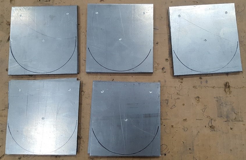
To make the end plates (these bolt to the front face of the landing gear knee), I cut out 5 sets of 3.5" x 3.5" stock that is 0.125" thick 4130 steel plate. These 5 sets come from a 9" x 18" sheet. Here they are:
Then, using cleco clamps, I clamped the original part pattern (with the drill guides) onto each piece of stock. Using a 1/8" drill bit, I mark the hole locations by drilling a small dimple into the stock. Before removing the pattern, I also traced out the profile of the part onto the stock.
Then, removing the pattern, the stock looks like this:
And, here's all 5 sets with the holes marked and the radius traced on the bottom:
Next, take the parts over to the drill press and drill pilot holes:
Then, open the holes to 5/16":
With the holes drilled, it's over to the band saw to trim off the majority of the material around the radius on the stock pieces. This will make it much quicker and easier to mill the profile around these parts in the CNC mill later:
Next stop is the big drill press to cut the initial inside hole for the torque tubes. This removes the bulk of the material so that the CNC mill can just open the hole a little to the required 2.010" diameter:
Here's what these plates look like when they're ready to go into the CNC mill to cut the center hole open and then profile cut the outside:
On to the CNC mill. I made a fixture to mount in the vise. For the 1st operation, the stack of 4 plates is bolted to the fixture and hang off the left side of the vise so that the end mill can go down below the bottom plate and cut the inside hole to precisely 2.010". That seems to be the number that lets the 2" OD 4130 tubing slide nicely and snugly through that hole. Here's the mill cutting the inside hole:
Here's the check of the hole size:
Now, for the 2nd operation, the stack is flipped over and bolted to the fixture over the vice. Here the 2" OD tubing is put through the stack to make sure the holes are all concentric before tightening the bolts to hold them to the fixture.
There is also a .160" aluminum spacer under the stack of steel plates so
that the end mill can extend below the bottom steel plate to profile
cut the plates and not have to cut into the fixture.
Here is what the stack of 4 stock parts looks like when they come out of the 2nd op on the CNC mill:
These 4 plates will make 2 sets of torque tubes. I put the other 3 sets in inventory for later. These are ready to get put in the welding jig for welding.
Moving on to the other end of the torque tubes I made up the short pieces of steel round bar. These get a hole pattern put into them that matches the pivot link in the torque box. That hole pattern is 4 holes in a square pattern. Two dowel pin holes are 5/16" diameter and are across from each other. The other 2 holes are drilled to .272" (letter I drill bit) and then tapped to 5/16" x 24tpi .
I did this in the manual Bridgeport mill using an 8" super spacer that has an 8" three jaw chuck:
Here's the 4 parts also ready to go into the welding jig:
The two tubing parts are easy to make. Simply measure them out and cut them to length. Then, slide them one inside the other. It comes out looking like this:
Here's all 4 sets ready for the welding jig:
Finally, making the bearing retainer rings is also pretty simple. Just cut off 4 pieces of 2" ID tubing that are 7/8" long. Then, put two holes into each part, 180 degs apart. These holes are 1/4" and only used to plug weld the retainer rings to the torque tube assemblies: Here is the set up in the big drill press to cut these 1/4" holes:
And, the last 4 parts ready to go into the welding jig:
Speaking of the welding jig.....Here it is:
It's simply a device that holds all the parts in the right places and orientations so that the parts can be tack welded together. Once they're tacked up - the assembly can be removed from the jig and the welding can be finished on the welding table.
The first step to setting up an assembly for welding is to bolt the end plate to the end of the welding jig, like this:
Then, place one of the short round bars with the hole pattern into the tapered end of the torque tube, like this:
Now, slide that whole assembly through the end plate while slipping a retainer ring onto the torque tube assembly:
Next, two 5/16" dowel pins are put into the pin holes, aligned with the slot in the welding jig:
and then the assembly is slid (bumped with hammer) to the left until the solid round bar is up against the shim plate on the left and until there is approx 1/16" to
3/32" of torque tube sticking out past flush on the front end plate, like this:
The last detail is to slide the retainer ring to the correct position and then plug weld it into position on the toque tubes:
Here is one final check of the correct location of the retainer ring. There is a counter bore in the upper 1/2 of the MLG Knee that must be able to allow the knee cap to fit snugly into position over the retainer ring - like this:
And, finally, the assembly is ready to be welded at the forward end:
And at the aft end.
Right now these are with my welding guy getting finished. I went and did the set ups with him and he tack welded each assembly. After we tacked up all 4 assemblies, I left them with him to finish up at his convenience. I'll have a finish pic for you when I get them back.
4. Builder Updates:
4.A. Ray - Most of Ray's recent airplane work is related to fixing problem with his hydraulic system. In Jun, he lowered the max output pressure of the hydraulic pump to about 1200psi (from about 1800-1900 psi). This caused an issue with the pressure pressure switch that turns off the pump when the upper pressure limit is reached. The system would cycle very quickly and chatter until you physically shut off the power to the hydraulic pump.
He had tried several things to stop this problem, but only recently nailed down the solution. Here is his explanation in an email to me:
"I did something I should have
done a long time ago, take the cover off the hydraulic pressure switch and watch
it when the gear cycled. It was very interesting to see all the pressure
fluctuations as the system works. The short travel of the microswitch is
definitely a factor, longer travel would allow it to stay on/off with more
variation of the system. The hydraulic pump does have some fluctuation as was
described to Bryan, but most of it seems to come from the loading as the parts
travel through their range of motion/loading/angles of travel. The result of
this is an accumulator should be in the system to smooth out the pressure drops
during the cycle. The other thing that should help is the capacitor across the
solenoid coil of the gear down solenoid. Sometimes the hydraulic switch is
tripped off when the gear comes down before the system builds full pressure and
the capacitor would provide the extra run time of the pump to run it to full
pressure.
I’m going to use the accumulator
that I made, but instead of an air charge I’m going to use elastomeric springs
to make it maintenance free. McMaster-Carr has a selection that I’m going to
try to see how it works out. The pressure fluctuations are not too large, but
the sensitivity of the switch acts on many of them, so I don’t think I need a
killer spring setup to smooth out the pressure.
I tried several variation of the
springs in the switch. Took several tries to get the right combination of
spring pressure to get normal operation. All of that will change with an
accumulator, so I will have to go back and re-adjust the spring settings.
Changing the springs in the fuselage is not the worst thing to do, just don’t
drop anything or it will disappear.
If it wasn’t for the tailwheel
not always wanting to stay down I could cut the pressure off with the green
lights. If the green lights are used it would still be a good idea to use the
capacitor to run the pump to full pressure since the pump cut off is rapid once
the lights come on and probably before the pressure is really up. This addition
might be something the other guys should look into if they use the lights to
control the pump shutoff."
Nice troubleshooting there, Ray. Glad you figured that one out. (The springs he's referring to are the springs in the VEP pressure switch. The hyd pressure acts against spring pressure to cut the switch in as the system reaches the lower pressure limit, and cut out as system pressure builds to the upper limit. By lowering the max output of the hydraulic pump, apparently these springs pressures have to be adjusted to compensate.) I will have to figure out a way to make this easier and more straight forward for the future builders. Thanks for the pointers, Ray.
4.B. Francis - Currently, Francis is my most active builder, by far. He is getting his main center wing built out, system-by-system. He sends lots of progress pictures as he fabricates and finishes each section of the plane. I really appreciate that, Francis!! I'm sure that the other builders and future builders also enjoy seeing your progress.
Since last May, Francis has tackled his aileron control linkages. This includes the installation of the idler brackets to the main spar near the torque boxes; the aileron bell crank in the outer wing; and the control rods that connect them. (He completed fabricating the bellcranks in a previous update.) Here is the bell crank area on his right outboard wing:
View from the other side:
Fitting the control toque tubes through the wing lightening holes:
Another view of the bell crank:
This is always the tricky spot, getting the inboard control tube to clear the top of the torque box (notice also the idler bracket just inboard/right of the toque box):
Here is the transverse bulkhead that makes up the forward wall of the inboard/aft/main fuel tanks and the outboard aileron control tube passing forward of it.
Another view of the excellent work that Francis does!
With the aileron control linkages installed, Francis moved on to the main control joystick and the associated parts. Here is some parts he used to fabricate his own aft stick (his kit was missing this part, so I sent him a collection of individual part drawings to help him fabricate the missing control stick):
They make up the main part of the aft vertical joystick/control stick. Here he is welding them to a piece of tubing that will make up a bushing for the bearings to get pressed into:
After welding, he will cut the tubing off on the right hand side:
Then, it looks like this:
Reaming the bushing for the correct size to press fit the bearings into the bushing:
And; mission accomplished (awesome work!):
No doubt, it does help to be an aircraft mechanic and an accomplished TIG welder!! Here is that aft control stick mated to the inner connecting rod that is located concentrically inside the main control joystick torque tube:
Here is the forward joystick connected to the inner elevator control linkage (the skinny tube, in the pics above and below, connects the forward and aft joysticks together inside
the main torque tube below the cockpit floor and controls the elevator
movement fore and aft):
The next pics I got from Francis, he was taking on the fabrication of the ailerons. Here it looks like he needed to make (or remake) a new rib for one of the ailerons. He made a die block and then bent the sheet aluminum over the die block. Without checking my parts info, I believe that his made from .032" thick 2024-T3. I can be pretty easily formed over a die with gentle-to-mild hammering.
Here's the main ailerons skin sitting trailing edge down in a couple of blocks of foam (it looks like) to hold it all upright while he works on them:
Installing the ribs:
And shims:
Mapping out the aileron trim tab actuator area:
Getting it straight:
and more straight:
Here is the aileron actuator spar and doubler ready for install:
Laying out the rivet spacing:
And more layout:
And, lots of clecos!!!
Lots of clecos!
Moving on to the next rib:
With the aileron fabricated, he next moved on to the aileron trim tab. It's a small part, but it's an important one and takes a lot of time to get it right
More clecos.....
It's a cleco pin coushin....
Nice work...
Here you start to see what the final form and function will be:
Here is the access panel work for the actuator and the tab above it:
Here is the nearly completed aileron with the trim tab and actuator access all installed. Very nice work, Francis!! It looks great.
I can't wait to see what part of the plane you will take on next! Looking forward to more progress pictures. Thank you very much for sharing your progress with us. Great job!!
4.C. Ernest - EZ has been working diligently to get his Prowler back to flying status. He recently got the engine an prop re-installed and ran the entire system for 10+ hours. Then, he dumped the oil to have it tested to see if the engine or PSRU are making any metal:
The oil inspection report came back nominal - meaning that it's perfectly fine. Neither the engine or the PSRU are making any significant metal or anything abnormal.
He then pulled the prop off one more time to do a visual inspection of the PSRU, etc. Here it is when it was buttoning it all back up:
EZ posing with his Prowler.
Here's a pic he sent me while he was doing his 10+ hours of engine run ups and testing:
He's getting really itchy to fly it again on it's second 1st flight. He's thinking it could happen by Christmas. That'll be a great Xmas present to himself!!! Keep up the great work, EZ.
5. EAA AirVenture 2017 Recap - This year AirVenture was really awesome because, my two youngest daughters accompanied me for the whole week. We actually enrolled them in an excellent EAA Day Camp program called Women Soar, You Soar (
WSYS). This program is specifically targeted towards high school aged girls that are interested in aviation and aerospace. It's a 4 day program that the girls get to see an do things at AirVenture that exposes them to women leaders in avaition, provides them mentors, they do team building break-out sessions and much, much more (they each got stick time in a Super Cub on floats!!). It is an incredible program and if you have HS aged girl(s), I highly, highly, highly recommend this program.
Anyway, here is the core "gang" at the Monday night concert on Boeing Plaza. Left to right is Bryan, yours truly, Byan's wife Lee, my middle daughter Alexandra, and youngest daughter Crysta:
Here are the girls at the pointy end of the B-1B:
As for the rest of AirVenture 2017 - there is no doubt that the B-29 "Doc" stole the show. Here is the business end of that plane - the Bombardier's station:
The restoration story of this aircraft could (probably already does) fill a book. What an amazing aircraft:
Here is some info on Doc:
What really made this year special at AirVenture was that fact that both Doc and Fifi were present and accounted for AND flying. The only 2 flying B-29's on the planet were both at OSH this year and they flew together. Here's a (bad) pic:
and, here's a little better video:
It definitely was a moment in history to see these two planes flying together again.
Of course, no AirVenture is complete until I find one of these to ogle:
I just dig these airplanes! Here's some info:
Here's a bunch of B6 guys wringing out an AirCam. That guy in the front is a Big Daddy!
And, that guy in the back could fly a barn door if it had a big enough engine on it!
The guy in the front on this ride should probably stick to Prowlers:
But, this AirCam is really a hoot to fly!!
AirVenture 2017 is the first time that the Blues were back since sometime way back, before sequestration. These guys are THE BEST, ALWAYS, END OF STORY, DROP THE MIC!!!!
I've probably seen 20+ Blue Angles demonstrations over the past 30 years. I am always blow away by how tight they fly. Nobody does it better - 6 at a time!
If you've never made the pilgrimage to AirVenture - plan to do it. You won't be sorry! It is ALL THINGS aviation, all in one BIG place and attended by anyone and everyone who loves airplanes, aviation, and aerospace. Ernest assures me that next year there will be a Prowler presence on the field at KOSH! And, Bryan has promised to try to compliment EZ's presence with another Prowler display. It's only 9 more months to AirVenture 2018!! More to follow....stay tuned.
That's all for this update. I will get one more year end update done next month. Until then, enjoy your fall season and thanks for stopping by.