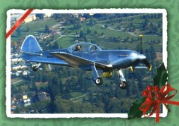
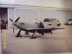
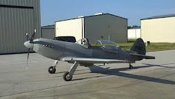
If you are interested in this kit, please email me. I will provide you with contact info so that we can talk Prowlers and answer any questions. Please use the feedback link on our Prowler Aviation website: Feedback.
Kit # 18- $15,000
(Located near Redding, CA)
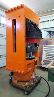
Over the past several years, while working with current Prowler owners, Prowler builders and Prowler enthusiasts, I have come to acquire the parts for this Prowler kit that I now have available to offer for sale. This kit is a “special” kit. It is comprised of parts that I have gathered from a variety of sources and it is currently, literally, inhabiting my shop office!
Some of the parts of this kit were from an original kit, some came from a Prowler enthusiast (who made several of the parts himself), some parts came from left-over inventory that I got from George, and several of the parts I fabricated over the past several years (while making parts for other kits that have sold or while making parts for current, active builders that were in need of certain parts). This kit is currently (approximately) a 98% complete kit (firewall aft). This kit also includes a used wing jig – an important fixture for holding the entire project during the initial stages of the build.
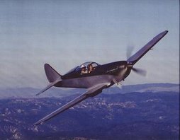
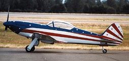
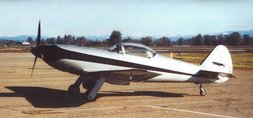
So, as you can see, this kit is a bit of a “Franken-Kit” - for lack of a better term. But, all of the parts in this kit are perfectly serviceable and they will make a solid, flyable aircraft in the hands of any capable builder. Because I found these parts over time and from different sources, I was able to obtain these parts at a fairly low cost. That is why I can make this a very affordable Prowler kit to purchase.
I am continually finding (or making) more parts for this kit. As I continue to add more parts to the kit, the price goes up accordingly. The only remaining parts of this kit that need fabrication includes:
1. Cockpit Canopy frame;
2. Engine nacelle parts (formers and skins between firewall and prop spinner).
3. Various servo and trim tab links.
Here are some photos of several of the sub-kits of the aircraft. The center and outboard wing main spars:
Here are the vertical stab & horizontal stab:
Aft spar parts on right, aileron parts in the box on the left:
Center wing leading edge skins on left, rudder skin in cardboard in back, elevator skins on back right, center main spar parts in small box in front, MLG torque box parts in tall box on front right, elevator parts in center box and rudder parts in boxes in back left box:
Outboard wing nose ribs, and mid ribs:
Main Landing Gear on the right side, cockpit framing parts in box on the left side:Fuselage parts in boxes and bags on left side, fuselage bulkhead formers in aft right boxes, luggage compartment parts in front large box, cockpit framing parts in small white box in front and MLG on far right:
Firewall parts:
Center wing framing parts in box on left and flap parts in box on right:
Here are some things to keep in mind as you consider purchasing this kit:
=> I will fully support the builder of this kit just as I have been doing for all of the current Prowler builders for the past 8+ years. I will be happy to put any prospective buyer in contact with any/all of the current owners/builders so that you may inquire about the quality of my support.
=> The outstanding (not yet included) parts of this kit are generally in sub-kits of the aircraft that are assembled much later in the build. You will be able to begin on this kit and work on it for at least a year (probably 2-3 years) before you will need any of the outstanding parts.
=> I will provide a list of the outstanding parts that are still needed for this kit to the prospective buyer. I can fabricate all of these outstanding parts of this kit, and I will do it at a reasonable cost. I estimate the approximate cost of these parts to be less than $300.
=> Some of the outstanding parts (skins in particular) will not be included in the kit. The material for these items can be purchased by the builder directly from any aviation supply vendor. I will provide a list of these parts on request and I estimate the cost of these parts to be about $1500. [There are several reasons for doing this. 1. The most important is that every builder to date (over 20+ years) has found out that 2024-T3 sheets age harden. The skin material provided in their kits got so hard while they were building their airframes that they couldn't get the skins to form to the airframe once they got around to putting them on. Many ended up having to buy new, softer sheets all over again - at additional expenses. 2. Also, each skin has to be hand-fitted and hand-formed to each specific airframe - so, why try to provide a fitted skin for something that hasn't been built yet? 3. This cost can be deferred until you actually need to purchase the skin material.]
=> This kit does not include the many additional items that will be required to build a flyable aircraft like; vendor supplied hardware (nuts, bolts, rivets, fittings, hoses, etc.), systems components (hydraulic pump, servos, switches, battery, wire, accumulator, brakes, wheels, etc.), avionics, FWF (engine, engine components, prop, prop hub, etc.). I can supply a partial list of vendor supplied items that will be required to assemble the aircraft. But, a complete list would be dependent on your preferences for outfitting the aircraft.
=> The cost of materials for the (included) wing jig alone (if built new from scratch) is $600-$800, and this item was not provided for any original kit builders. Each of them had to purchase these materials separately and build the wing jig before starting the main wing assembly (Several other sub-kits can be completed before you'll need the wing jig).
=> Even with the remaining costs for outstanding parts of this kit, the total cost of the kit (approx. $16.5K) will end up being only roughly 2/3 of the cost of a comparable RV-8 kit ($25K). But, with a Prowler you'll get at least 1/3 more performance than the RV-8!
=> Price does not include shipping. I will be happy to help coordinate shipping, or coordinate local pick-up, depending on the desires of the buyer/builder.
Because of the low acquisition cost of these parts, and taking into consideration the pedigree of this kit, the price is set to make this a GREAT value. So, if you want to get into a Prowler project at a very reasonable cost – it does not get any better than this!
------------------------------------------------------------------------
There is also a very special opportunity (possibility) with this kit. For the right builder, this kit can be built as a unique, absolutely one-of-a-kind aircraft! The complete story is long and detailed. But, I'll be happy to explain it fully to anyone interested in building a Prowler that has a cockpit that is about 1.5" wider and could be made to harness a big-block motor - instead of the Y block motor required for a Prowler. There really is an interesting opportunity here - and I guarantee you'd have a rare bird!
------------------------------------------------------------------------
Heck, if I wasn't so focused on trying to rebuild this kit aircraft manufacturing company, I'd just keep this kit and build it myself. But, if I did that, I'd end up spending all my time and money to get one airplane going and I wouldn't get Prowler Aviation back into production (and, hopefully, produce many airplane kits).
------------------------------------------------------------------------
There is also a very special opportunity (possibility) with this kit. For the right builder, this kit can be built as a unique, absolutely one-of-a-kind aircraft! The complete story is long and detailed. But, I'll be happy to explain it fully to anyone interested in building a Prowler that has a cockpit that is about 1.5" wider and could be made to harness a big-block motor - instead of the Y block motor required for a Prowler. There really is an interesting opportunity here - and I guarantee you'd have a rare bird!
------------------------------------------------------------------------
Heck, if I wasn't so focused on trying to rebuild this kit aircraft manufacturing company, I'd just keep this kit and build it myself. But, if I did that, I'd end up spending all my time and money to get one airplane going and I wouldn't get Prowler Aviation back into production (and, hopefully, produce many airplane kits).
Really! Buy this kit! It's a great kit! It's an excellent price! And, I need to get it out of my office!
Some additional Information You Should Know:
Here is a little history on original Prowler Aviation kits. None of the original Prowler kits were ever actually shipped as “complete” kits. Because of the way things transpired with the original Prowler Aviation, most of the original 15 kits that were ordered got shipped as partial kits (basically they shipped with as many parts as George could make from the initial 50% kit deposit that he received from the original customers). In order to get the remainder of the needed parts, the owners of the original 15 kits had to make arrangements with George to purchase them (effectively pay the other 50% of the cost of the kit).
The current owners (that have built a completed, flying Prowler from one of George's original kits) did this. They paid George to make the remainder of their parts. Others chose not to pay the other 50% of the kit cost and those kits remained as incomplete kits. Some original kit owners paid for some outstanding parts to be made, but not all of them. This left quite a range of “completeness” in what is currently available out there for second hand Prowler kits. (There are VERY few second hand Prowler kits remaining.)
A lot of these kits ended up in long term storage and were never built. As a result, the individual parts typically come with dust, scuffs and other evidence of their age and experience - but nothing that would affect structural integrity or serviceability of the parts. However, I am able to fabricate any parts (firewall aft) that are found that the builder would prefer to replace – if needed.
In any event, this kit should be considered to be “NOS” kit (a kit from New Old Stock – to borrow the phrase from automotive restorers and builders). While the majority of the parts of this kits are original production run parts, there are a many newly manufactured components (all made from the original tooling) to help make the kit more “complete.”
A complete kit would be considered a kit that has all the parts that are listed in the most complete “parts list” that I have been able to put together (from several original Prowler Aviation documents). That list will be provided with the kit. These original kits DO NOT include readily available, common aircraft components like; wheels, brakes, hinges, servos, etc. Also, none of the systems (electrical, hydraulic, fuel) components are included in the kits, such as: pumps, valves, switches, wiring, gauges, etc. (None of the original kits had any of these either.)
Building a Prowler aircraft is a complex task. While building a Prowler kit will be much easier if you have developed some metal aircraft building skills prior to commencing your project, there have also been several novice builders (starting out) who have completed beautiful aircraft. There is an awesome network of Prowler builders who are happy to help you complete your kit. We also have a Yahoo! Group to help network with other builders (ProwlerBuildersGroup).
If you are interested in this kit, please email me. I will provide you with contact info so that we can talk Prowlers and answer any questions. Please use the feedback link on our Prowler Aviation website: Feedback.
.jpg)
.jpg)
.jpg)
.jpg)
.jpg)
.jpg)
.jpg)
.jpg)
.jpg)
.jpg)
.jpg)
