Hello Everyone,
Welcome back. Since we are 3+ months into 2018, it's time for a quick Prowler update. Most of the past two months has found my time consumed with getting qualified to go back to work, and then actually getting back to work. With a whole afternoon off in a hotel room, there's no better time to post an update. So, here's what I have for you this time:
1. Making My 1st Set of MLG Hydraulic Actuators
2. Another Fix To The MotionMaster
3. Fabricating Long Aluminum Channels
4. Builder Updates:
A. Bud Is Flying Again!!!
B. EZ Is Ready To Go - 2nd First Flight
C. Ray's Having MLG Problems
D. Francis Keeps Marching Along
E. Eric Is Working On Ailerons
Most of the work that is the content of this update post was completed in late Dec 2017 and Jan 2018 before I went back to work. Admittedly, since the end of January, I've not had much time to get in the shop. I'm hoping to reverse this trend and get in the shop enough to complete Kit #18 before AirVenture this year. That's because it's looking pretty certain that EZ will be flying his Prowler to KOSH this year for AirVenture 2018. And, Bryan has committed that if EZ flies his Prowler to the show, then he will try to trailer his Prowler up to display as a "work in progress". So, we could have 2 Prowlers at AirVenture this year! The Prowler brand is quite likely going to get a fair amount of attention if this happens. So, I'm hoping to have at least one kit to sell when I get the inevitable question(s)....
Anyway, more to follow on the AirVenture 2018 Prowler presence. For now, on with the update.
1. Making My 1st Set of MLG Hydraulic Actuators - One of the big outstanding assemblies left on the "To Do List" for Kit #18 is the hydraulic actuators that move the MLG up and down. Since I had a few weeks of uninterrupted time left in the shop towards the end of my medical LOA time - I wanted to tackle getting these components made. In general, they are not incredibly complex parts to fabricate. However, I found that engineering that goes into sizing and fabricating of parts associated with O rings is pretty complex.
The MLG Hyd Actuators are essentially made up from 5 parts (not including the vendor items - O rings, locknut and spherical bearing). Here is an exploded CAD drawing I made several years ago:
I refer to these 5 parts as the:
A. Piston Rod;
B. Piston;
C. Cylinder;
D. Live End Plug (cylinder plug that piston rod passes through);
E. Dead End Plug (cylinder plug that facilitates attachment to wing spar);
I will go through the fabrication of these parts in this order.
A. Piston Rod - George made these from 4130 steel rod. I originally purchased enough 4130 rod to make 1 set of these. After I made them I looked at them closely and discovered that the mill finish on these was very rough. The surfaces were covered with pits, waves and other deformities that I was certain would tear up any O ring after a few uses - even if I tried to smooth and polish the surfaces of them. I was also concerned about the oxidation of the surfaces of these rods when the gear were extended and they were exposed to air for long periods of time.
After a discussion with Ray, I decided to pitch that set of piston rods and start over with piston rods made from 303 stainless steel. So, I sourced some correctly sized stainless rod and cut them into the necessary lengths. Here is what one looks like when I started:
The first thing to do was to put it in the lathe and reduce one end to 3/8":
Here is one completed and ready to cut threads to 3/8" fine pitch:
Instead of trying to cut the threads with the lathe, I decided to use a thread cutting die and use the lathe to align it and begin the thread cutting:
Once I had 2-3 threads cut on the end, then I took the rod out and put them into my 8" super spacers that was mounted on my mill table. Using this to hold the rod, I continued cutting the threads using a hand threading handle holding the 3/8" fine thread die:
Here is one that is done:
Next step is to drill and tap the other end of the piston rod. This is drilled and tapped to 5/16" fine threads to hold a tie rod end that will be used to attach to the MLG brace attach point. Here is the pilot hole getting drilled in the lathe:
Drilling the correct sized hole for the 5/16" fine tap:
And, here is the setup I used to start the tap in the hole of the piston rod. I placed the tap in the drill chuck mounted in the tail stock and then turned the headstock by hand to get the tap started straight and aligned:
Once I had a few threads tapped in the lathe, I put the rod back in the super spacer and continued hand tapping the holes all the way:
The last thing to do was to put flat sides on the end with the threaded hole to provide a means to "hold the roll" when threading the 5/16" tie rod end into the end of the rod. I did this using a 5C collet and a square collet block I pinched in a vise. Then, it's just a simple short cut on each side with a 1/2 end mill:
With that done, it was time to put the rods back into the lathe and clean them up. I used the lathe with a fine pitch file to knock off any large "goobers." Then, I used 220 grit emery cloth, 440 emery cloth and finally 600 emery cloth to polish the rods to a pretty clean, smooth finish:
Here are 2 finished sets of my piston rods:
B. Piston - The pistons are fabricated from 7075 Al rod. Here is a piston "puck" in the lathe getting the hole drilled that will get tapped to 3/8" fine thread:
Here is the 3/8" fine tap getting started in the correct sized hole:
Again, once the treads were started straight, I put them in the vise and completed the tapping by hand:
With this done, I put the pistons back into the lathe and cut a counter bore on one side with a 5/8" end mill. This is for the locking nut to sit into to lock the piston to the piston rod. I don't have a pic of that, but here is the piston mounted to the piston rod and chucked in lathe. This set up was used to cut the grooves for the O rings that will seal the piston in the cylinder:
Here is one of the pistons after the O ring grooves are completed:
Here are 3 sets of pistons and rods that I made:
On a recommendation from Ray, I decided to make a couple sets of these
with dual O ring seals. Ray experience some pressure bypassing around
the piston. It turns out that the bypassing was caused by worn out O
rings - but, I thought I'd try a few sets of these anyway, just to see how they work
out.
C. Cylinders - The cylinders were probably the easiest of these parts to make. I simply had to lop off a length of 4130 steel tube and cut 3 holes in each end. I did that in the 8" super spacer again and used the mill to cut the holes. Here is the set up:
Initially, I just spot drilled the holes, then went back and cut the hole the correct size with an end mill:
The only other thing I had to do with the cylinders was to thoroughly deburr the holes on the inside and then run a 320 grit ball cylinder hone in the cylinder to give them an initial polishing. This will prolong the life of the sealing O rings on the pistons.
D. Live End Plug - One end of the cylinders must be "plugged" with some thing that will allow the piston rod to pass through it. I refer to this as the "live end". The other end of the cylinder has a plug that allows for the whole assembly to be mounted to the wing spar. I refer to this as the "dead end" of the actuator. End plug also provides for a threaded hole to act as port for the hydraulic oil to flow in and out of the actuator.
Both ends are made from a 7075 Al rod. The live end is bored out to the correct diameter and has O ring grooves cut on the ID for sealing to the piston rod and O ring grooves cut on the outside to seal to the cylinder. Here is one of the plugs being squared up and cut to length in the lathe:
Here are two sets of both live end and dead end plugs after initial forming (live end plugs in front and dead end ones in back:
Here is drilling the pilot hole through a live end plug:
Next, I drilled the hole to slightly under the piston rod size. After that, I ran a reamer through the hole to get a uniform bore:
Next, I turned the live end around in the chuck and used an end mill to drill a counter-bore part way into the live end. This provides a passage for the oil to flow around the piston rod and the inside of this counter bore:
Here are all three sets of pistons, piston rods and live ends pseudo-assembled (no O ring grooves on the live ends yet - but there are grooves on the pistons):
Here is a live end chucked in the lathe and cutting the outside O ring groove (Note: I'm using an ID grooving tool to cut an OD groove - so, I had to move the tool all the way back, turn the lathe the opposite direction and cut while moving the tool in -X direction). Cutting the 1st O ring groove:
And, cutting the 2nd O ring groove:
Here is the live end with both OD grooves cut for the O rings. Ray recommended trying to use double O ring grooves on these parts to make the part more stable inside the cylinder and to cut down on any leakage. We will see how this design works out, over time:
Here is a close up shot of the double O ring grooves on the ID of the live end. This might be overkill, but again I thought I'd try a double O ring seal on the piston rod, just to prevent leakage. (If one is good, two must be better - right!?!?)If it turns out to add too much drag to the piston rod, I reasoned that I can always just remove one O ring.
Here is the set of three pistons, rods and live ends, again (with O rings on one piston on the left):
Remember the hydraulic ports that I mentioned earlier, well here is the setup in the mill to drill the holes for the live ends. Each live end gets 3 holes drill and tapped that are 120 deg apart. In one port goes the hydraulic 90 deg elbow to attach the hose, and the other 2 holes get pipe plugs. The three of these fittings are what holds the plug inside the cylinder. Here is the setup:
Later, these will get tapped to a 1/8" NPT thread.
E. Dead End Plug - Here is one of the dead end plugs getting the hydraulic oil port cut into the inside end. Later, there will be 3 radial holes drilled into the dead end plug - one of them will connect to this drilled hole to make the oil passage:
Here are the 3 sets of dead end plugs after the O ring grooves were cut and before beginning the machining of rounded tabs:
Also, before beginning the machining to form the rounded tabs on these parts, I drilled the 3 radial holes that are 120 deg apart. Here's that setup:
Here are all the parts of one set of actuators with the parts placed in their relative positions:
In the picture above you can see a sample of what this dead end will eventually be on the right side there in between the two dead ends that are still not complete. These were actually the most difficult of all the actuator parts to fabricate.
This rounded tab is formed by removing a fair amount of material from each side of the round rod to make a flat, square tab. Then, the tab gets rounded off and a bore (with a counter bore) gets put into the tab. This bore is to make a pocket to press the spherical bearing into that makes the attachment point for the actuators. Here is a partially finished live end next to the inventory sample I had on hand:

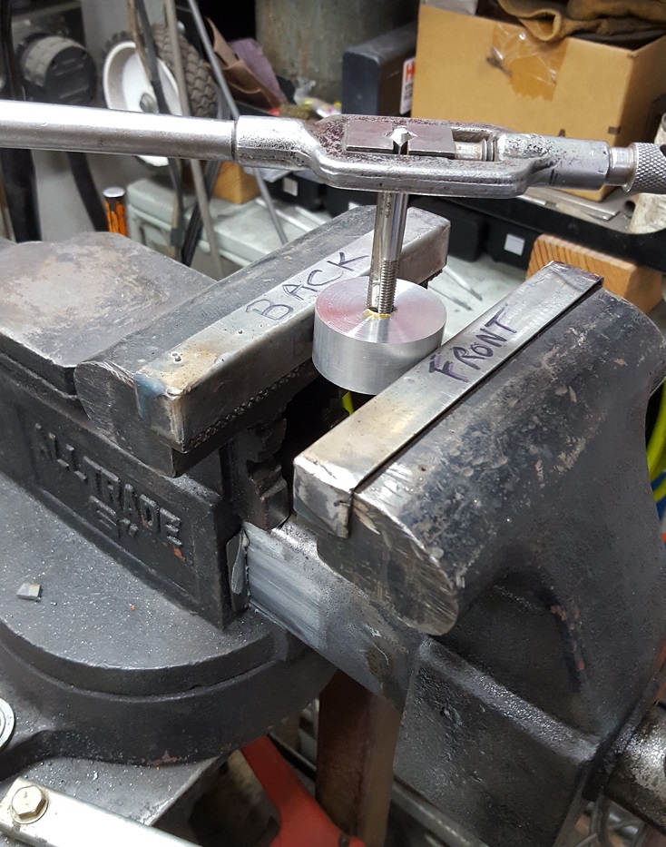
To make this rounded tab, the first thing I had to do was figure out how to hold the parts during machining. I decided to use a section of the same tube that the actuator cylinders are made from. Next, I found a piece of square tubing that I was able to just press the round tube inside of. Then, I welded it in place and cut a slot 1/2 way thru the assembly (lengthwise). I welded a 3/8" nuts on top of the slot one each side and welded 5/16" nuts under the slots. With a 5/16" bolt thru this, it forms a clamp to hold the part. Additionally, the square tubing on the outside provides for a quick, convenient way to turn the assembly 90 deg to do the 2nd and 3rd operations to form the rounded tab. Here is the assembly during fabrication:

The 3rd bolt mounted on the top of the fixture is to provide for a means to position the part correctly in the fixture. The 3/8" bolt has the threads on the end turned down to the precise correct side so that it just slips into one of the (as yet) unthreaded holes. This holds the part in the same orientation if taken out and put back in, and it also help to prevent the part from slipping inside the round tube. Here is the fixture mounted in the vise on the mill table:
And, tightening down the bolts to clamp the part in place:
Here, one of the dead ends has just had the flat, square tab formed on the end of the part:
Here is the dead end after the flat, square tab has been formed:
Here is the dead end after the tab has been rounded off, and the bearing pocket is being formed (notice the fixture has been turned 90 deg and the bolt heads are now facing the front of the mill):
Here is a dead end plug after fabrication and getting de-burred:
Here is one of the bearing that gets pressed into the bearing pocket on the dead end tab:
Here is one set of the dead ends with the bearings pressed into place:
At this point, the only thing that needs to be done is to figure out a way to keep the bearings from backing out of the pockets. There is a formal process for this, known as "staking" a bearing. There are many ways to stake a bearing - the simplest is to just use a punch and pound divots around the edge of the pocket. While this will work, it can come out looking a little non-uniform and inconsistent.
I thought about it a while and decided to make a tool to use bearing balls to press divots into the material around the bearing pocket. I envisioned a pin that would go down through the bearing and have that position 4 bearing balls in the correct place. Then, I could put it in the arbor press and stake the bearing. Here is the tool I made:
This is how it works:
After pressing in the hydraulic press, this is how the dead ends looks after the bearings are staked:
Overall, the appearance is good and the bearing is secure. By using only 4 stake points, I reasoned that "if" the bearing ever needed to be removed, or replaced, you could press the old bearing out, re-bore the hole and put a new bearing in. Then, the bearing could be re-staked with the bearing balls turned 45 deg to fall in between the existing staking divots.
The last remaining task was to tap all the plug holes to 1/8" NPT. Here is a live end in the drill press getting the tap started. I used a "
Center-It" to place the part under the drill press chuck.
Then, I hold pressure down on the drill press spindle while turning the
spindle by hand. This gets the tap started in the hole straight and square:
Once I have 3-4 threads started, I take the part to the workbench vise and finish tapping the hole by hand:
Finally, here is one set of actuators cleaned up, painted and assembled (except for the 1/8" NPT pipe plugs and hydraulic line fitting) :
That is one more set of parts to take off the "To-Do" list for kit #18. For a good view of where and how these actuators work, see Ray's Builder Update in Section 4, below.
2. Another Fix To The MotionMaster - After all the lathe work to make the hydraulic actuators, I decided to mix it up and get some router work done with the MotionMaster to fabricate some long channel parts for kit #18. The day came to put some aluminum on the table and fire up the machine - and when I went to push the button......there was no "fire." What-the-heck, now!?!? I pulled the cover off the rotary phase converter and found this:
It might not be easy to see in the above pic, but the main power relay on the upper left is hanging by the wires. Here (below) is the place where the relay is supposed to be - the main mounting plate and the 4 "legs" are still mounted there, but the relay body is broken off:
Here is the back of the main relay. You can see the 3 of the 4 points where the "legs" broke off.
After I got it all apart, I remembered that this part was originally damaged when it was shipped to me when I was building the 25HP rotary phase converter. During shipping, the jarring knocked a couple capacitors loose inside the box. Then, those rattled around a broke more components - like the main power relay. At that time, I just wanted to get the rotary phase converter built and running - so, instead of taking the time to send the part back for a replacement I just "Krazy Glued" the legs back onto the relay. Well, the Krazy Glue held for quite a while, but let go sometime during the 3 years that I hadn't used the machine.
A little more thorough repair was in order now. I "Krazy Glued" the legs back on again, but this time I ruffed up the plastic with a Dremel tool all around the breaks:
With the legs all ruffed up, it looked like this:
Then, I slathered on a layer of JB Weld onto the ruffed up areas to help reinforce the Krazy Glue repairs. This should help the joint stay stable and not break again:
After the repair cured, I put it all back together and got the machine running. Here is the machine trimming a sheet of aluminum:
3. Fabricating Long Aluminum Channels - Kit #18 needs several long aluminum channels fabricated for it. I needed to make some 2024-T3 (.032" thick) to make the longeron covers for the cockpit. I also needed to fabricate the (0.040") outboard wing trailing edge hinge support channels for the kit. And, lastly, the kit needed a set of five 2" channels (0.040") that make up the upper and lower mid-framing longerons.
To start this project, I cut up part of a sheet of 0.032" Al for the cockpit longeron covers, and an entire 4' x 8' sheet of 0.040" aluminum into strips the correct width to make the various 2" channels. Here's the MotionMonster cutting the 0.040" strips:
Once I got the strips cut and deburred the edges, I hauled out the 8' press brake and got re-acquainted with it. It's probably been 3-4 years since I used it to bend any long channels. I think the last time I used the press brake was when I formed the outer wing spar channels and the main center spar skin flanges. That was years ago, already!
Anyway, here is one of the outer wing trailing edge hinge support angles being formed in the press brake. It's hard to see because the camera didn't focus on the close end of the part (look just up from the bolt head in the middle left side of the picture and you'll see the fuzzy looking end of the part being formed):
This part is nearly 8' long and has a 48 deg flange formed on each side - and at the same time the part is tapered in width along the entire length (this picture below has the narrow end in the foreground):
Here are the same completed parts with the wide end closest to the camera:
These hinge supports were a little tricky to make accurately in the press. I figured out the best way to form them and wrote it all down in my book of secret tricks for next time!
After forming the hinge supports, I went on and formed the 2" channels for the longerons and the longeron covers. I've made a few sets of these in the past, but it still took a few practice runs to get them right. Once again, I (re)figured out the best way to form them in the press brake and wrote my notes in my book Prowler building secrets for next time. Here are all five of the longerons for Kit #18 on the left, and the cockpit longeron covers on the right side:
Here is a closer pic of the ends of the 5 longeron channels. The press brake that I build with Dad all those years ago is a little tricky to use sometimes, but it is still the best tool for the job. It makes these long 2" channels nice and straight with a uniform bend angle:
In the interest of full disclosure, I cut up several (OK, many) strips of the 0.040" that were too narrow (I did a mental math error entering numbers into the CNC control - UGH!). So I had to look through my parts lists and find out how many parts there were that could be made from narrow strips of 0.040" 2024-T3. I ended up making lots of parts to put in inventory to used up that material. Here is one example:
They are the inboard and outboard flap angle clips that form the leading edge corners of those flap segments. These go in the corners where the flap spars meet the end ribs. So, in the end, I was able to recover gracefully from this goof - but, I hate it when I do stuff like that!
4. Builder Updates:
A. Bud Is Flying Again! Yay! - Ray & I got a quick email from Bud on March 9th to let us know that he got his Prowler flying again. In his own words:
After a year and a half of frustration and expense, and with a lot of help from the Prowler-ites, Jaguar 12BT took to the air today. With a couple of small issues, the flight went well and I am ecstatic to have her flying again.
Today’s flight was, primarily, to seat the piston rings. During ground run, the EGTs were all over the board with #6 being 200 deg less the next higher EGT. A compression check revealed air blowing by the rings and out the breather. Ground running at 2400 RPM overheated the coolant temperature within :05. The only answer was to fly.
During TO, the airplane accelerated a bit faster than I remembered and required more aggressive right rudder than before. Within :10, the engine ran smoother and all the EGTs were within +/- 30 deg of each other.
Bud
Here's a little more background info on this. Bud's Prowler suffered a PSRU failure nearly two years ago that took the airplane out of service. The pinion gear that George employed was a 2 piece design. This design was susceptible to a fatigue mode failure that fractured off a part of the gear inner bore shoulder and sent it bouncing around inside the PSRU. After analyzing this failure, Ray & I (with input from all the Prowler owners & builders that have George's gearbox) set out to design and procure new one-piece pinion gears for all the current owner/builders. It took a while, but we eventually got the new gears.
This failure also badly damaged Bud's crankshaft (splines). Bud did a huge amount of research and thorough search for a machine shop that could repair his crankshaft and simultaneously mate the new PSRU pinion gear to it. To date, Bud, Ray and Ernest have installed the new gear into their PSRUs. However, Bud was the 1st to fly with the new pinion gear. Congratulations, Bud!! Very impressive work! Thanks for sharing your great news.
B. Ernest Is Ready To Go (2nd First Flight) - I got a call from EZ last week. He's all ready to get his Prowler in the air again - just waiting on the paperwork. This will be his first flight in his Prowler since doing extensive work on the airplane, including changing out his PSRU pinion gear (mentioned above). Here is a recent pic he sent me on Apr 9th with the associated text message => "Snarlin'! Aaahhh.....paperwork! The bain!":
It looks awesome, EZ! Looking forward to seeing the airplane take off again, soon. We are trying to coordinate time off of work so that I can jumpseat up to SEA and join him when he does this flight. I hope that I can be there to photo and video document the flight.
On a separate note, one of the mods that EZ did to the plane was to add the same oil spray line to the PSRU that shoots a small stream of engine oil down onto the bull gear. It's a system that Ray designed and installed on his plane that incorporates a NOX "pill" that nitrous guys use in race cars . After the install, EZ was seeing oil pressures drop to less than 20PSI when the oil was warm. He basically had the option to try a higher viscosity oil or replace the NOX pill with a pill that has a smaller orifice. He decided to try to oil first. Here's his report:
Put the 10-50 with Moly oil in and the oil pressure problem is.........wait for it.....GONE!!! @ 190F oil temp and 1200 RPM, oil pressure is 32psi instead of 18! NICE!! Of course we have to wait until the 1st oil analysis results to know for sure that there is sufficient lubrication. But she’s all buttoned up and just waiting for the paperwork to go fly. Talk to ya soon. EZ
So, for anyone that wants to install this oil spray system on their PSRU, this is good info. If you want more details on how Ray & EZ did this, let me know. I'll send you some info.
Outstanding work, EZ! Hopefully, we can do this in the next few weeks. See ya soon!
C. Ray's Having MLG Problems - The last time I was down to see Ray, we tried to cycle his gear. For some reason, the right MLG was catching on something and not going all the way into the gear well. Here's a video:
After a little troubleshooting, we determined that the post on the end of the gear yoke that normally rides up and into the gear uplock was not hitting the mark. Instead, the post was hitting the wrong place on the uplock preventing the gear from going all the way into the well. This caused the sequence valve for the gear door to not get activated which kept the door open. The door remaining open prevents the pump from turning off.
So, we figured out that all out. But, what we couldn't figure out was, why? Why was the gear post not lining up the same as before? Well, Ray did more investigation and has determined that something has happened in the torque box in the area of the pivot link. Somehow, something has worked loose or has otherwise failed and it has moved the gear strut out of its normal arc of travel. This drawing shows the area where Ray thinks the problem is:
Fortunately, Ray put access panels in the torque boxes. But, unfortunately, he will have to cut access panels in the wing skins in order to gain access to this area and investigate further. Right now, he has other projects he is working on and needs to finish. Then, he'll get on this. I'll let you know what he finds. Stay tuned.
BTW - here is a pic of Ray's right MLG well. This pic shows the shows the location and orientation of the MLG Hydraulic actuators that I discussed earlier in this update:
While is was visiting Ray last, we dragged the airplane out of the hangar and Ray let me jump in and fire it up to run the engine for a while. Here's a pic from that day:
What a great looking airplane, and I really appreciate the engine run time, Ray! It sure sounds awesome! Can't wait for your 1st flight too!!
D. Francis Keeps Marching Along - Francis is still chugging along on his project. He's sent me several pictures over the past 3 months. It looks like most of his work lately has been on the ailerons. This looks like a tool that he as made to set the stiffener rivets on the ailerons (and flaps, too):
Here is some of his work on the aileron stiffeners:
The rivet set tool, at work:
More aileron work:
Installing the doubler around the aileron servo pocket:
One of the aileron spars with the actuator attach plate getting installed:
More overall aileron pics:
Note the rolled leading edge that closes the gap at the top, trailing edge of the wing skin:
Top skin of the aileron - notice the Prowler pics on the back wall - love it!!!
Keep up the excellent work, Francis! You are doing an excellent job. And, thank you for sharing your work with us. It is great to see your Frog Prowler accomplishments over there in Euro-land!
E. Eric Is Working On Ailerons - The only other builder update I have is that Eric emailed me asking for typical aileron deflection (angle) measurements for the airplane. With the help of Ray and Bryan, I got him some of those measurements for him. Later, he replied with this:
Thank you so much for this information everybody. (It) is same degree (angle measurements) on mine. I suppose I built correctly. Eric
Excellent! I'm happy to hear that your project is going well, Eric. Thank you. Please send a pic when you have time.
----------------------------------------
Well, that is all for this update. I started this update over a week ago! Finally, just now, getting it spell checked, grammar checked and published. I'll post at least one more blog update prior to AirVenture with details about the possible Prowler presence there this year! I hope everyone has a great spring.