Normally my blog updates cover several facets of what's going on at the new Prowler Aviation. But, this time, it is focused solely on the 400 ton press I found last year. The goal is to get this press set up to do the rubber pad pressing of all the Prowler "formed" parts (wing ribs, bulkhead formers, floor stringers, etc.) In that respect, this press is destined to be a very important part of this company's production capability. Also, because I have so much information to cover, I decided to do a blog update just dedicated to the press and my endeavors to remodel and re-configure it to work as a rubber pad (pseudo-hydroforming) press.
I plan to follow this update closely with a more normal blog update that will cover several other things that have been going on with Prowler lately. It's actually been pretty busy so far this year and I have a fair amount of information to pass along.
On with the 400 Ton press update.
WARNING - THIS BLOG UPDATE IS LONG AND FILLED WITH LOTS OF TECHNICAL STUFF ABOUT HOW A 400 TON SLAB SIDE PRESS AND IT'S HYDRAULIC SYSTEM WORKS. THIS IS NOT FOR WIMPS! YOU COULD BE BORED TO TEARS OR FORCED TO FALL ASLEEP WITH YOUR LAPTOP ON YOUR LAP. PLEASE PROCEED CAUTIOUSLY. YOU HAVE BEEN WARNED, CONTINUE ONLY AT YOUR OWN RISK!!!
In the last blog update I reported that I purchased this 400 Ton press from a gent south of Carson City, NV. and left the story with the press sitting here in the driveway in front of my shop:

After a bit of imaginative thinking, I decided that if the Egyptians could build a pyramid without a 5Klbs forklift - I should be able to get a mostly square, almost unbreakable hunk of steel off of an equipment trailer. I started by mounting a large timber to two lifting lugs that were attached to the bottom side of the press (as it laid on the trailer). Then, I jacked the press up and put some 2" thick black poly slabs under it. These poly slabs are really pretty slippery against one another. So, I fixed one set of black poly slabs to the press in two places and then put another layer of slabs under those that were secured to the trailer deck.
It was just a matter of blocking up the end of the trailer and then pulling on the base of the press with a small cable puller. The thing slid very easily toward the end of the trailer.


1. Make a CAD drawing of the finished form of the press;
2. Make a materials list for purchase and ordering;
3. Figure out a hydraulic pump unit to power the press;
4. Re-configure the steel that will become the bolster;
5. Re-configure the steel for the top of the rubber box;
6. Install lower spacers;
7. Repair, install and align the lower platen;
8. Build and install the upper spacer;
9. Test the hydraulics (pressurize the press);
10. Build and install the rubber box.
11. Install the bolster;
12. Fabrication Summary;
And, here are a few items that became important after more info was discovered during the build:
13. Begin seal repairs;
14. The Seal Repair Plan.
Let's dive into these, one section at a time.
1. Make a CAD drawing of the finished form of the press - The first step in any of my projects these days is to make a 2D and 3D CAD drawing of the work involved. In this case, I had to determine the size of rubber box that would be needed so that I could make ANY Prowler part. After a bit of research I figured out that the rubber box had to be a 16" x 36" rectangle. (The largest part I have to form are the fuselage formers that are just aft of the cockpit. This sized rubber box is required to be able to form 1/2 of that bulkhead former - then put the two halves together.) This press was designed and built with 24" x 24" platens. So, looking at the press on the horizontal plane, somehow I was going to have to reconfigure the shape, or "footprint," of the platens from 24"x24" square to the 16"x36" rectangle.
Looking at the press vertically, I had to close the "air gap"of this press (space between the top of the piston and the bottom of the press head) from around 36" to approximately 4". Using several spacers and platens that I got with the purchase of the press I was able to close this air gap down to about 14". To get me down to the 4 inches that I wanted for the final air gap, I designed an upper spacer for the press that brought the distance from the top of the bolster to the bottom flange of the rubber box to approximately the 4" I needed. And, at the same time, changed the shape of the press from 24" x 24" of the press head to 16" x 36" of the rubber box.
BTW- if I wanted to be able to maintain the same PSI exerted on each square inch of this new configuration, the two shapes (old and new) would have to have same amount of area (or at least close). If you do the math, you'll find out that (conveniently) the area of a 24"x24" square and a 16"x36" rectangle are both, exactly, equal to 576 sq. in.
So, here is the design that I came up with that I believe will work well for this machine:

You can compare these parts of my press to the drawing I used in the last update which shows the "theory" behind the design of a rubber pad press (or pseudo-hydroforming press):

2. Make a materials list for purchase and ordering - With a design in mind for the end product, I had to take a look at what I had available for spacers and other parts that came with the press to see what I could re-purpose. Then, I'd have to purchase materials that I didn't have on hand to use to fabricate the rest of the parts that I needed.
Here is the stack of platens and spacers that were on the press when I purchased it. I removed all of these from the press before transporting the press back to my shop. These came back with me on my trailer and the press itself was brought back on my buddy's equipment trailer.

The 3rd piece down from the top is the lower platen of the press. It is a 4-1/2" thick slab of steel specially fabricated to hold shoes that slide up and down against the side slabs of the press. These shoes help to keep alignment of the ram and upper and lower platens while operating. This would be cleaned up, repaired and used pretty much as is. It weighs in at about 800 lbs (including the alignment shoes) and is represented by the light purple part in the CAD drawing above.
The next piece down was a 2-1/4" thick slab of steel that was used as a spacer on the press in a previous life. I decided that this piece could be reconfigured from it's current 24"x24" to 16"x36" and used to make up the top of the rubber box. Sides would be welded to the edges of this piece to form the rubber box. This piece weighs about 360 lbs and is the black piece inside the rubber box in the CAD drawing above. Adding the sides and the flanges on the rubber box, the weight of the rubber box comes to about 650 lbs.
The bottom piece on the stack above was a 4-3/8" thick slab of steel that was also used as a mold spacer on the press in a previous life. It looked to me like this would make a perfect bolster, but it also would have to be reconfigured from 24"x24" to 16"x36". This piece weighs roughly 750 lbs and is the red part in the CAD drawing above.
With those parts designed, the only remaining part to have to fabricate was the upper spacer. I found photos of a couple of spacers that I saw on a few other presses and used these as a guide to design the upper spacer of my press. This upper spacer would serve two purposes. First, it would reconfigure the top half of the press (the rubber box) from the 24"x24" shape to the 16"x36" shape. Second, it would fill up the remaining air gap to give me the 4 inches (roughly) that I decided on for space between the bolster and the rubber box when the press was in the "open" position. I figured 4" would be adequate for loading the dies and flat blanks before pressing parts, and also OK for removing the formed parts and the dies after pressing. All in, this upper spacer ended up weighing nearly 600 lbs and is represented by the dark grey part in the CAD drawing above.
So, adding up all the spacers, platens, rubber box and bolster, the total weight of these parts comes out to about 3,600 lbs. This is a big project.
Ultimately, the upper spacer pieces and the sides of the rubber box are the only parts of the press that I needed to buy steel for. I was able to buy almost all of the steel for these pieces as drops and remnant pieces from my local steel supplier. The only two pieces that I had to buy and have cut to size were the top and bottom plates of the upper spacer. The drops and remnants are much cheaper than buying new stock. Still, all in all I have nearly $1K into the steel that I had to purchase to get the press reconfigured. Imagine the cost of I'd have had to buy all the other parts discussed above!
3. Figure out a hydraulic pump unit to power the press - One of the first tasks that we needed to accomplish in this project was to get a hydraulic unit working to power the press and move the piston. To do this, I decided to see if I could use the old Williams Model 30 hydraulic unit that I got with the 100 Ton press that I got from George when we bought Prowler Aviation. Here is a picture of the unit previously installed on the 100 ton press:

Anyway, this hydraulic unit has been taking up space on the shop floor ever since I removed it from the 100 ton press. I re-checked the specs on this unit and it is advertised to produce up to 5,000 PSI at a flow rate of 10 gallons/min. The new 400 ton press is designed to work at 2,500 PSI - so this unit should work fine from a pressure standpoint. I remembered that this pump was only producing 1250 PSI when I used it previously. Checking with Williams, I was told that the pressure could be increased, but you had to pull the pump from the tank and re-set a pressure relief on the back of the pump. No problem with doing that (it was relatively easy to do).
So, this pump should be capable of making the required pressure. But, what about flow rate? How long would it take to cycle the press? Time to do some math. With a 20 inch diameter ram in the 400 ton press and a calculated maximum stroke of 6 inches, the volume of hydraulic fluid required would be (pi*r*r*h = 3.1415*10*10*6) = 1885 cubic inches - or, about 8.2 gallons required to move the ram from the bottom of stroke to the top of the stroke.
With an advertised flow rate of 10GPM, this pump should be able to move enough fluid under the ram to move it to the top of stroke in about (8.2 gals /10GPM) = .82 min, or about 50 secs. That seems like a reasonable length of time to me for a limited production application that I am envisioning. In reality, the stroke will probably never reach a full 6 inches and the upward cycle time will probably be more like 35-45 seconds. Sure, if I was trying to stamp automobile parts, this would seem like an eternity and you couldn't make any money trying to run at this speed, but for making Prowler parts - I think this will be sufficient for now.
Well, looking at the red box in the picture above, it didn't take long to calculate that the max amount of hydraulic oil that it could hold was no where near the 8 gallons required to move the piston to the top of stroke. In fact, it only holds about 4.5 gal. So, if I was going to try to use this unit, a supplemental reservoir was going to be required. We decided to fabricate a supplemental tank from a piece of 12"x12"x1/4" wall square steel tubing. We welded a 12" square piece of sheet steel to each end and added two 1-1/4" pipe nipples to allow for rigidly attaching the extra reservoir to the main pump tank and to allow the hydraulic fluid to flow between the two tanks. The end result is pictured below:


Well, it was working and it was making more than 1250 psi, but not the ideal solution yet. I decided to hook up an adjustable, external relief valve that I had on hand. I figured it could be used to more accurately set the system pressure. I also figured that if I set the external relief valve pressure to something lower than the pump relief pressure, the pump should be able to circulate some oil and I would be able to ramp the pressure up more slowly by adjusting the pressure of the external relief valve. I also reasoned that at max pressure more relief capacity (flow) would allow the 10GPM to "go somewhere" instead of just dead ending into a pipe plug and relying on the overflow capacity of the internal relief orifice. Here is the unit with the external relief valve installed:


Well, hydraulically speaking, this was progress - but since we could only raise the cylinder 2 inches (only had about 4 gals of hydraulic oil available at the time) there was still too much air gap in the press and the piston didn't have anything to "push against." So, we really couldn't test how much pressure the large piston seal would hold. That would have to wait until a little later, after we got the upper spacer in place and I went and got more hydraulic oil.
4. Reconfigure the steel that will become the bolster - As I mentioned in section 2 above, I decided to try to reconfigure the 4-3/8" thick slab of steel that I got as a spacer with the press to be used as the bolster in the new press set-up. In order to do this, I had to figure out the most practical way to cut the 24"x24" piece and then weld it back together as a 16"x36" part.
This is what I came up with: cut an 8" wide strip off of any side, then cut that 8" strip into 4 pieces that are 6"x8". Next, take two pairs of these pieces and join them to make two parts 6"x16". Then, add those two pieces to each end of the larger 16"x24" piece. The end result would be what I needed:


5. Reconfigure the steel for the top of the rubber box - Using a similar process as he did to make the bolster, Dad reconfigured the top of the rubber box from the 2-1/4" spacer discussed in section 2 above. Here is the end result.

Overall, this part came out pretty flat and not warped very much after the welding process. It is just a little distorted, but since this side will have the rubber attached to it inside the rubber box, it is acceptable for this part to not be perfectly true and flat. Later (below) you will see us add sides to this piece to fabricate the rubber box.
6. Install lower spacers - After completing work on the hydraulic unit and welding of the bolster and rubber box parts above, we moved on and began to assemble some parts of the press. The first step here is to bolt the bottom of the 2 lower spacers to the top of the piston/ram. The ram has two threaded holes for 1" diameter bolts to use to mount the lower spacer. Initially, these holes were not aligned (front to back) with the press walls. So, we had to spin the piston a little - as I'd mentioned earlier. Here is the piston top ready to receive the lower of the 2 lower spacers:


7. Repair, install and align the lower platen - With the two lower spacers installed, the lower platen was up next. This is the largest, heaviest single piece to be put on the press. Here is the lower platen installed, bolted to the lower spacers and with the shoes setting on top. The shoes and the surfaces that they slide on had to be prepped and straightened before they could be installed.


8. Build and install the upper spacer - The upper spacer design was made from essentially 5 main pieces, plus 6 smaller gussets. The 5 main pieces were the upper plate, the lower plate and 3 vertical plates. The upper and lower plates of the upper spacer I had fabricated and cut to size by my local steel supplier. Here is the design:


With those holes in place, it was time to install the upper spacer:


At this point, the air gap was small enough that I could stack slabs of 2" thick poly in the press and run the pressure up on the piston seal. That is discussed next.
9. Test the hydraulics (pressurize the press) - Once we got the upper spacer installed, it closed the air gap enough that I could find a few more poly slabs and put a stack of them in the press. Then, we could have something for the piston/ram to push against and build up pressure in the cylinder. That would allow us to see how well the piston seal was holding. Here is what that looked like:


MAJOR BUMMER!!
Oh-well! Back to work on the remaining components of the press.
10. Build and install the rubber box - Undaunted by catastrophic failure of the press sealing system, we moved on to fabricating the rubber box. This was a pretty straight forward assembly. We started with the top of the rubber box that I have discussed earlier:


11. Installing the bolster - As I mentioned previously, the bolster still requires some machining to get it fit for use in the press. So, we did not install it. Here it is, again, setting a moving dolley getting ready to load into the mill:


12. Fabrication Summary - And, finally, here is the project pretty much completed. The only things missing in the picture below are the bolster and some paint on the new parts. I think I am going to paint the new parts with a black paint and keep the rest of the press this color orange. As I was cleaning it up one day before starting work on the 1st lower spacer, I thought of the nickname for this machine. It's orange and it is going to crush parts......so - "Orange Crush"! OK, it's not all that original - but it is accurate and descriptive:

As you see the press sitting in the picture above, we had worked on the project for about 2 full weeks - pretty much most of the day, every day. It was a big project, but it all came together exceptionally well. Now, if I can just get it to hold hydraulic fluid - LOL!!!
Here is the project summary, by the numbers:
=> Days to complete - about 14
=> Small oxygen bottles consumed - 3
=> Small acetylene bottles consumed - 1.5
=> Welding rods consumed - about 40 lbs.
=> Hydraulic fluid in the system - about 10 gal.
=> Hydraulic fluid spilled - a trash can full of soaked paper towels
=> Cost of all supplies, steel, etc. - about $1800
=> Trips to town to buy all that stuff - about 20
=> Two weeks in the shop cutting, grinding, cussing, machining and welding with the "ol' man" - PRICELESS!
THANKS POP!
I really have to give a huge THANK YOU to my Dad for helping me with this project. There is no way that I would have been able to complete this project without his help; especially with the welding. And, there was a lot of that with this project!

13. Seal Repairs - Since I still had about 3 days off of work after Mom and Dad left this spring, I decided that there was no time like the present to get after this leaking seal issue. I really wanted to know what I was up against. So, the first step was to take out all 16 bolts (1-1/4" bolts with 1-7/8 hex heads) holding the seal retainer ring down:

Then, carefully, and squarely, lift off the seal retainer ring:


The next idea was to put a bunch of wallboard screws into the top of the urethane seal ring and use a pry bar to pull it up. That turned out to be a good option. At this point I planned on just replacing the seal ring anyway - so it didn't matter if the screws damaged the ring. Here it is coming up:


Here is the gland seal cavity that is between the piston/ram and the outside wall of the press cylinder:

Here is a drawing of what the cross-section of this area of the press looks like:

Here is the seal that was in my press, after cleaning it up and a little dismantling:


Notice in the picture of the seal that came out of the press, that the O-ring has been in there so long that it has become "figure 8" shaped. I'm pretty sure this should be round - but age has caused it to permanently deform and it would no longer "load" the seal at low hydraulic pressure.
I also noticed that the urethane is very hard. Maybe it's supposed to be like that, but I can't deform it with a thumbnail or with gentle pressure with a small tool. Seems to me to be too hard. I'm not sure at this point if urethane hardens as it ages - but I'm going to change the seal anyway, so it really isn't an issue. The next time this press operates, it will be with a brand new sealing ring!
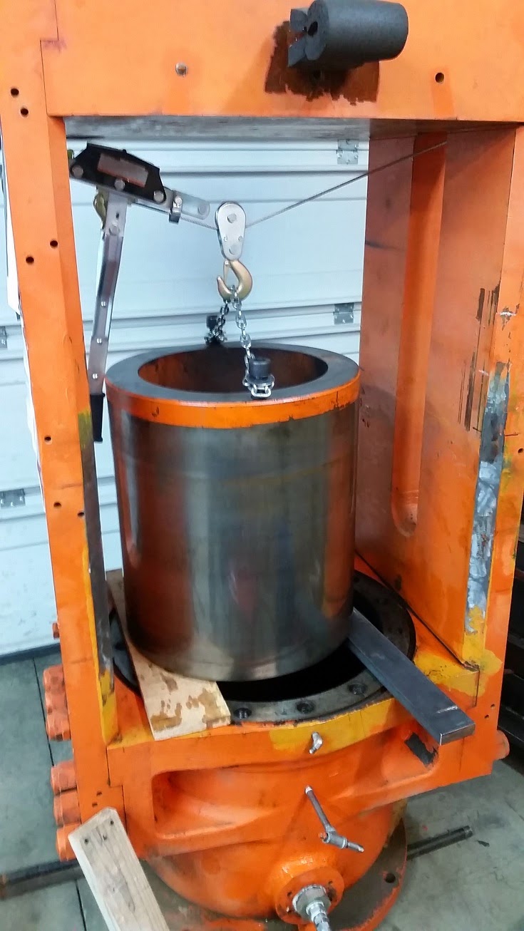
OK, moving on. It quickly became obvious to me that there was no way that I'd be able to adequately clean up this gland sealing cavity and put this thing back together and NOT have it leak again, unless I pulled the ram out and got some room in there to work on the area correctly. So, out came the be rod/ram/piston - all 1500 lbs of it:


Next, I went to work on the outer wall of the gland sealing cavity. I scraped it down with a putty knife and removed a bunch of black, grainy, semi-hard junk from the outside wall. Then, I hit it with a wire wheel on a drill motor. As, I wire wheeled various spots on this outer wall, dust would fly off and then the wall would become this shiny spot of pitted and eroded and creviced bare metal. RUSTED!!!

AT THIS POINT, THINGS STARTED TO BECAME MUCH MORE CLEAR! I surmised that at some point in the history of this press, this cavity got exposed to a lot of water and oxygen. I suspected that it was from older compression rope packing that got wet and rusted the wall of the gland seal cavity. Later, someone wanted to install a urethane seal, but it would not seal against this rust pitted outer wall. So, they put some kind of mastic, or filler, in the pits and cracks to smooth the wall. What I found was the junk that left after this mastic degraded and turned to the black, grainy, semi-hard material that I found stuck to the seal ring and to the wall of the seal cavity.
Just to be sure, I called an expert that has worked with and rebuilt these presses for over 40 years to solicit his insight. His name is Bob Westfall and he works at Rubber City Machinery Corp. He is a great fella - very friendly, extremely knowledgeable and totally helpful. Turns out that I was pretty close with my hypothesis. Bob said that the rusting came from the fact that this press was used in a water-hydraulic system at some point. When companies use these presses in banks of 20, or 50, or 100 - they use a common pumping unit and a huge manifold to distribute the high pressure liquid to each press. But, the cost of hydraulic oil in these systems becomes enormous. So, they use water-soluble hydraulic systems (essentially some form of water & glycol - like the coolant in your car). Well, sooner or later, the seals in these presses leak a little. This causes the fluid level to go down, so, the operators fill the system back up with water and don't check the mix ratio of the fluid. Eventually, the fluid gets diluted to the point that there is no more rust inhibitor left in the system and the system begins to oxidize (rust) in the weakest point in the system that oxygen can get in....around and near the gland seals. The net result is rust, just like I found on this press.
14. The Seal Repair Plan - Now that I know what's wrong with the press, I can start to formulate a plan to get it repaired and useable again. As I see it, there are essentially 4 parts, or phases, to complete the necessary repairs to the press:
1. Rebuild the gland seal cavity wall - While talking to Bob about my press problems, he told me that the correct and permanent way to fix the press is to take the press completely apart, have the pitted areas filled with weld and then have a machine shop with a large vertical mill (or a really large lathe) bolt this 2,000 lbs part into one or the other and machine the wall smooth again.
He also, confirmed that one of the semi-permanent "Band-Aid" fixes is to put some kind of epoxy metal into the pitted and rusted areas to build up the wall and then and smooth it back out so that the seal can press against this built up wall. This is what I found when I took mine apart - only whatever mastic was used in this previous repair had failed. He mentioned a material called Belzona.
After doing a fair amount of research on this topic and doing a cost-benefit analysis, I've decided to go with the semi-permanent repair process and rebuild and smooth out the outer wall of the gland seal cavity with the Belzona 1111 product. It seems to be pretty amazing stuff. You can read all the great info about it at the link above. But, basically this stuff is an industrial version of JBWeld - only much better.
There is a good likelihood that I will be able to get 5 to 10 years of use out of this press (or more) with this repair process. Since I won't be using this press in a true industrial setting and cycling it 500 times each day, I could get acceptable results with the Belzona repair.
The repair will go like this: 1st - mask off around the area where the rust pitting is and sand blast just this area with the pitting. Then, clean everything well and wash the area to be treated with Belzona with a good de-greaser like MEK or Acetone. With this step complete it should look like this:


To do the correct, permanent repair would require me to take the press completely apart. This will add a significant cost (time and money) to this project that I'm not prepared to commit to right now. I would have to have to get a forklift to take the press apart, then get the cylinder base in to a machine shop that could do the repairs. It would be a lot of time and expense to get this done for a tool that (at least initially) I will only use a few times a month - if that. It would be nice to know that this tool will be everything that I think it will be for making Prowler parts BEFORE I take on this added cost.
If this press ends up working well to make Prowler parts - I can fairly easily take it all back apart again at some point in the future and do the permanent repairs. Now that I know what it will entail, it would probably only take a week to get it done. I took the press parts that we fabricated all back apart and off of the press in a matter of a couple of hours and I had the piston out and on the crib pile later that same day. Given that I now have this experience, taking the press apart the next time should go even faster.
I ordered the Belzona, it comes in a 1 kilogram container with a mixing boards and some basic tools;

2. Fill/repair the vertical scratches in the ram - It turns out, one of the applications that Belzona 1111 was specifically designed for was to fill scratches and gouges in hydraulic rams. So, I will also use it to fix my ram as well. The only difference between the wall of the seal cavity and the ram is relative motion. I will have to smooth the seal cavity wall as much as I can, but since there is not really much motion between the seal and the cavity wall it should seal well. However, I will have to try to polish the ram repairs super smooth because the inner flange of the seal rides directly on the ram surface under 2500 psi pressure. Any roughness on the ram will literally tear the seal apart and drastically shorten the life of the seal.
3. Get a new urethane seal - While talking with Bob about my press, he also recommended a company to get a new seal ring from. This will just be a matter of discussing my situation with the sales rep that he referred me to and determining the correct type of seal and seal material to use. I will order whatever the sales rep recommends for me and wait for it to arrive.
4. Put it all back together and test it again - Once the Belzona repairs are done and I've gotten my new urethane seal, I can simply put the piston back in the press and install the new seal. Then, I'll button everything back up, fill the press with hydraulic oil and bleed the air out of the system. After I re-install all the parts of the press I will put the stack of 2" poly slabs into the press, turn on the pump, run the pressure up and hope for the best.
In my future blog updates I'll report in with my progress of these repairs.
Wow - What a massive blog update! Thanks for sticking with me through all that. If you made it all the way through this update you deserve a medal! You must be as big of a machine geek as I am to stay interested through all of that! I guess I just really enjoy the challenge of taking these machines that I find, fixing them up, modifying them to fit my application, and get them running again.
Of course, each one of these machines that I get working to make Prowler parts is also building the value of the company itself. That fact that they will be part of returning Prowler Aviation into a viable kit aircraft manufacturer and eventually get more Prowler aircraft out flying in the world is even sweeter!
Thanks for checking out the blog. See ya next time


