AHEAD IN THIS UPDATE
1. Building A Gantry Crane
2. The Prowler 400 Ton Press Saga Continues
3. Pexto Shear Mobile Base
4. EDG Thermostat Housing Extension
5. Ernest Is Making Awesome Progress
6. Ray's Taxi Tests
7. Latest From Bryce
8. An Update From Francis
My main focus lately for Prowler Aviation lately has been getting the 400 ton press fixed and back together. It is the last major machine that I need to start doing some real work on cutting wing rib dies and making initial parts to test fit onto my spar in the shop. The other major focus of my time lately has been on getting the rest of the parts made for the kit that I have in my shop office. I will continue to work on completing the remainder of the outstanding parts and assemblies. As soon as I have that kit complete, I can get more aggressive on advertising it for sale. I hope to have these final parts finished up early in 2016 and get the 400 ton press back together before summer.
On with the update.
1. Building A Gantry Crane - I have been searching for a reasonably priced forklift to buy for the shop to help me take apart the 400 ton press. I haven't been able to find anything that I like at a cost I'm willing to pay. Recently, I found a Craigslist ad for steel pallets for sale from a local tractor dealer. Turns out, the place is more of an importer of LS tractors, and what they are selling are the red steel pallets that you can see below that the tractor bodies are shipped in on. It was kind-of an amazing place. There were literally 1000's of these tractors sitting on the shipping pallets waiting to be taken down and assembled for distribution around the dealers in the western US.
The pallets are made of 3"x3" steel tubing that is 1/8" thick., and at $15 a piece I figured I could use them to make lots of good stuff. So, I went and bought 6 of them: Here are the 4 remaining ones after I got them home and got 2 of them cut up in pieces and and then got the various lugs, legs, and steel plates removed from the remaining four:
Believe it or not, I really didn't have the idea for using these to build a gantry crane until I got them home and cut up. Once I did, it looked like a good material to use for that, and my imagination kinda took over. First, I doubled up two pieces to make the bottom of an A frame. Then, added a couple pieces that came off of the pallets that had a U shaped plate that fit over the square tubing:
These made a good way attach two upright pieces to for an up-side-down T shape and they came that way on the pallets. So, I didn't even have to do any fabrication for these - just weld them on! After adding the uprights I had two T frames started:
Next, I added the sides of the A frames and rounded up some casters I had laying around:
I installed 4 casters on each A frame (2 on each end) and cleaned up 4 of the 12mm holes in pads at the top of the uprights. Then, I added 2 more 12 mm holes in each pad so that I would have a total of 6 bolts holding each end of the beam of the gantry. Here's a pic of the pads before adding the 2 extra holes in the middle:
And, here is a pic of the top of what each A frame looks like with the 6 holes in each pad. Here I have fabricated the plates that will get welded to each end of the beam and put them in place on the mounting pads welded to the tops of the A frames:
The last thing I did to complete each end A frame was to weld on a smaller pad with two 12mm holes just below the beam mounting pads. This would give me a place to add a small brace in each corner to help stiffen the gantry. Here's the A frames pretty much ready to add the beam:
They turned out great and I made them so that they would be as tall as possible, yet still have the tops just barely clear my garage doors in my shop (with the doors open). This would allow me to use the gantry to load things onto trailers, etc. with the shop doors open.
Next, I had to find a beam to use. A trip to the local steel recycling place rewarded me with a nice 8" wide flange I-beam for just a little over scrap steel price. This beam weighed almost 250lbs and I got it for $70 cash.
It was perfect for the gantry I was designing. It was just over 9 feet long which would allow me to back my biggest trailers under it with about 1.5" to spare outside of each of the wheels of the trailer and inside the A frames on the ends. I welded some small ears to the bottoms of two plates that I fabricated and drilled to match the pads welded to the uprights. Here you can see the beam end plates bolted into place on the pads at the tops of the uprights:
The piece you see between the uprights is one of two short spool pieces that I made to fit between the A frames and hold them together for use when I have the gantry disassembled for storage. Using my tractor, I was able to lift the beam just enough to get it into position on the ears welded onto the end plates. Then, I tack welded the beam into place once I got everything squared and plumbed. I also tack welded in the small braces in each corner. Here is how it looked just before I took it back down to do all of the final welding to the end plates and braces:
Once I got all the welding done and the welds cleaned up I put the beam back up onto the end frames and finished reassembling the gantry. BTW - I burned up about 15 lbs of 1/8"- 6011 welding rod on this project. Fortunately, I had a good friend stop by recently and dropped off a 50lbs box of rods that he had laying around that he wasn't going to use. (Thanks, Bryan!)
Next job was to install the beam trolley that I bought at HFT. You can see that here:
The next step in the project was to find, inspect and fix up (as needed) one of two chain hoists that I'd bought from someone off of Craigslist several years ago. The price was right and I figured that I'd find a use for them some day. Well, that day finally arrived. I chose the 3 ton chain hoist and here is what I found when I opened it up:
Needless to say, there went a whole afternoon cleaning out the old, dried, caked-on grease and re-greasing this unit. I also chose this hoist, because it had a removable hook on the top that would allow me to attach the hoist directly to the lifting lug that came with the trolley. By getting rid of one of the hooks on the hoist, it would give me a few more inches of headroom over the top of the press that I needed to take apart. Here's a picture that helps explain this better:
That was it! Now, the only thing left to do was to stress test the whole rig and see what it could do. I decided to hook the gantry to the head of the press and then try to lift the entire press in one piece. I have calculated the weight of the whole press (minus the ram) to be about 7,000lbs (3.5 tons). If my gantry could lift all this and not fail, then I can be sure that it will do the job for any of the individual parts of the press - or, anything that I might want to lift in the future that is less than 3 tons. I'm happy to report that the chain hoist was complaining a little bit, but it lifted the entire press without any problems or failures! Here's a pic of that stress test:
This will be a handy tool to have around in the future. I was able to get the steel for this project for $30 and a beam for $70. I was short a few casters, so they cost me $100 at TSC. The trolley cost me $90 at HFT and the chain hoist cost me $25. All in, this gantry cost me $315, about 3 days of fabrication and who knows...maybe $30 in electricity for the welder (thanks to the California Energy Extortion system).
Anyway, HFT sells a 1 ton gantry for $720 and I am into mine for less than 1/2 of that cost. Plus, I have 3 times the lifting capacity and it can straddle a full sized trailer. I'm an really happy with that!
2. The Prowler 400 Ton Press Saga Continues - Initially, as I have discussed in past blog updates, I was going to do a kind-of semi-permanent repair to my 400 ton press using Belzona. But, after seeking a lot of advice and after a several months of thought and consideration I've decided to fix the leaking press the right way. Mostly, I figured that since I already have this thing nearly all apart anyway - it just makes sense that now is the time to take the press the rest of the way apart and get the necessary pieces repaired, correctly and permanently.
After a lot of phone calls, emailing, visiting machine shops and talking to many folks a lot smarter than me - I have found out a lot of information and gotten a lot of suggestions for how to handle this press repair project. Here is a run-down of the needed repairs:
A. The base (cylinder) needs to have one of the sealing cavity walls turned down get rid of the pitting and erosion of the wall surface. I have outlined this in previous blog updates. It also needs to have the throat (sleeve) inner surface turned down to remove pitting, scaring and run-out (out-of-roundness removed). Here is a picture of the sealing cavity wall and the inner face of the throat:
This work would ideally be done on a large boring mill. I haven't been able to find anyone locally with a boring mill large enough to handle the almost 1 ton base. I have, however, found a local machine shop that has a gap-bed lathe large enough to swing this part. So, it looks like that is how this part will be repaired by Mark at A&A Machine Shop.
B. The ram (piston) needs to have pitting, scaring and run-out removed. All of the local machine shops that I visited to discuss the cylinder repairs have referred me to company called Chrome Craft in Sacramento to do the repairs to the ram. Keep in mind, this ram is 20" in diameter, is 22.5" long and weighs approximately 1,500lbs.
After several discussions with them about my ram, Chrome Craft has proposed the flowing repairs: First, they are going to grind down my existing ram by 0.030" over the entire 22.5" length (to remove material from a previous repair). Then, they will do a rotary, stainless steel MIG welding process to it to build up the removed material. After that, they will re-grind it down to the desired diameter and finish the repairs by hard chroming the ram with 0.002"-0.003" of hard chrome. This will leave me with an essentially brand new ram.
C. The urethane seal, itself, needs to be replaced with a new one. Because I will be changing some of the sealing wall dimensions, I may have to have a seal made to fit my exact dimensions. A seal manufacturer called Chesterton was recommended to me.
They can fabricate mono-seal packing rings for any application to any specific seal dimensions without any special tooling or setup fees. The seal that they provide for me should be a perfect slide-in fit.
D. The slab sides of the press have 45 degree chamfers cut into the inside corners that need to be cleaned up and re-machined to remove un-evenness and scaring. I will have another local machine shop (Tomasini Blacksmith & Welding) do this work for me. They are great folks and have helped me out several times in the past.
You can see some of this chamfer cuts in the picture above. It's the areas with the paint removed on the inside corners of the slabs, starting just above the base of the press.
With all the information gathering and repair planning behind me, the next step was to use my newly fabricated gantry crane to get the press apart. The plan was to first remove the head of the press, then to take off each of the slab sides to end up with just the base. Here is the gantry rigged to the head of the press:
In this picture above, you can see the channel iron that I mounted to each side of the press and tied together with a 1/2" all-thread. This set-up will allow me to "walk" the slab sides outward on the lower stud bolts on each side to get needed separation to remove the head from the press. The all-thread kept the tops of the sides from "flopping" out and kept them standing (more-or-less) upright while the head was removed. This set-up worked great and here is a picture after I started to get one of the sides of the press to move away from the head:
Once I got a small gap started, then it was just a matter of using a pry bar and wood blocking to "walk" the sides out and away from the head (above) and the base (below):
When I got the sides far enough apart, I simply removed the head and set it down on some dolley's to move it out of the way:
With the head removed, I rigged the gantry to one side. I then removed the all-thread set-up and removed the lower stud bolts to free the one side of the press:
Here is the first side coming away from the base:
And the side removed:
Then, I had to set the side down on the concrete on a piece of blocking. I then grabbed the side in the middle with the gantry so that I could lift it and get furniture dolleys under each end so that I could move them out of the way (and around the shop as needed):
After removing the second side in the same manner, the base was all that was left:
The next morning, I loaded the base onto a small trailer I have for transporting to the machine shop that will do the repairs:
And, here it is ready to roll out of the driveway to the machine shop:
A few days later, I loaded the ram using an engine hoist into the back of my truck. I was able to deliver this to Chrome Craft in Sacramento before one of my commutes to work in LA.:
As of right now, the work will begin on each of these two parts sometime in early Jan 2016. I'll have more updates soon.
3. Pexto Shear Mobile Base - I have this PEXTO 52" gap shear that I bought a few years back when I purchased the Prowler stuff from Mike Dodd's step son.
I have always wanted it put on some sort of a mobile base so that I could move it around the shop if needed. After I finished the gantry, I had a few decent pieces of steel tube left over. So, I took a few measurements, dug out some 4" steel channel that I have stored in the shed and started fabricating:
The idea is to make something to allow the sides of the shear to drop into the channels on the sides of the base. Then, I will attach the casters to raised plate steel pads that will allow the casters to be recessed and not cause the shear to be significantly raised up. Here is a picture of the mock-up of the caster attachments to the mobile base. In this pic you can see that the casters are actually attached to hinged pads that will be attached to the inside of the mobile base. This will allow the casters to be extended and retracted so that the mobile base can be either mobile, or stationary:
Here is a picture of the mobile base assembly after the casters have been mounted and the frame fabrications is complete:
And, here is one of the casters mounted with the 1/2" extension and retraction bolt installed. In this picture the bolt is threaded all the way in and the mobile base is "live" and can be moved:
When the bolt is backed all the way out, the caster retracts and the mobile base lands on the concrete and becomes stationary:
With the fabrication complete, I used the gantry crane to lift the shear and remove the wooden pads under each side:
Then, I positioned the shear over the mobile base:
And, dropped it into place:
The base works great. This is another big "hang-fire" project that I've wanted to get done for years! Next up for the shear is converting it back to a stomp shear. Sometime in it's past, it was converted from a stomp shear to a pneumatic shear. For carefully cutting 4' x 12' sheets of aircraft aluminum, I really want to have it be back to a stomp shear that I can more precisely control. So, I'll have more info on my attempts to convert it back in future updates.
4. EDG Thermostat Housing Extension - In the last blog update I reported moving my back-up diesel generator into its new home in the building I built for it. Now that it is in it's new home I have gotten started on finishing the wiring and other work that needs to be done to get it set-up to work in the case of a power loss.
I've run the generator for up to 4 hours at one time, but I was always nearby and I was frequently checking the power output and engine parameters (most importantly, oil pressure and water temp). All (good) generators are built with engine protection circuits that will shut off the engine in case of a loss of oil pressure or very high water temperature.
I have already researched the low oil pressure switch that I need. I found and bought a 15psi normally open (N.O.) pressure switch online. The engine already has a small manifold installed with three 1/8" NPT spots for attaching oil pressure switches or sending units. So, the low oil pressure switch is now installed (standing out the top of the oil press manifold):
After some additional research, I've found that most generators with diesel engines use a normally closed (N.C.) switch with a 230F set point to shut the engine down in case the engine starts to overheat. The Kubota engine that I found for my generator came out of a refrigeration unit and only had a one small (1/8" NPT) port for attaching a water temperature sending unit (provides the signal for a water temp gauge). Somehow, I was going to have to find and add a high water temperature (HWT) switch. All I could find at a reasonable cost for a HWT switch is was a normally open (N.O.) switch with a 3/8" NPT male fitting.
A 3/8" NPT port is kinda large and I needed to locate a place to put it that was in contact with engine coolant. After weighing a few options, I decided on the only location where I could get contact with coolant and NOT have to cut, drill, or in some way make a hole in the engine head or block. That place was the thermostat housing. You can see it here at the base of the radiator hose:
I don't have a great side view, but here is part of the thermostat housing on the upper left:
My idea was to fabricate an extension to the thermostat housing so that I could make an area where I could drill and thread a hole to install the temperature switch on the engine side of the thermostat. That way, I would always have high water temp protection, even if the thermostat stuck shut. This picture (below) shows most of the parts that are involved with this switch installation. My first step was to trace the base of the thermostat housing cover onto a piece of paper. Then, I extended one of the sides that would provide a decent amount of material to cut and thread a hole for the switch:
Here is a mock-up with most of the parts in place (relative to each other):
With a basic profile and height determined, I went to the CAD software and CAD'ed up the part:
I found a suitable block of aluminum in the shop, put it in the mill, squared it up and faced off the top:
Next, I got the profile cut out using a 1/2" x 2-1/2" end mill:
Next, I used a smaller end mill to cut the main hole, the bolt holes, and the counter bore for the thermostat lip to sit in:
Here's a test fit of the thermostat to make sure the lip fits well and the gasket holes all fit correctly:
Here's all the parts test fitting with bolts in place:
With everything looking good, I flipped the part over and cut the bottom side down to the desired thickness. Here's the part I ended up with after that:
Same part after cutting the switch hole and threading it with a 3/8" NPT tap:
Another test fitting:
And, finally, everything test fitted in place on the engine:
Since then, I've finished the install of this extension, put all the hoses and clamps back in place and re-filled the coolant. In the next update, I will address my plans for using these switches to install the wiring and finishing the engine protection circuits. Essentially, these switches will be used to keep current feeding through a fuel shutdown solenoid. Current will be constantly passing through these switches until either oil pressure is lost or the coolant temp gets too high. If either of these conditions occurs, current will stop and the fuel solenoid will loose it's pull. When that happens, the fuel shutoff valve will close under spring pressure. More to follow.
5. Ernest Is Making Awesome Progress! - In the last update I posted about having George in the shop and he helped me make parts for Ernest's Prowler. These parts were going to help him rebuild Prowler #5 after the forced gear-up emergency landing. Since then, EZ had been working incredibly hard to make his goal of getting the Prowler back up and running by Christmas. I'm happy to report that he has mostly made his goal. He has run the engine again, just before Christmas! Here are a couple pictures of his rebuilt radiators with brand new, racing style heat exchangers installed. These are much more efficient (and lighter) than the old GM heater cores that George used:
Here are his re-skinned inboard flap sections. Just the most inboard trailing edges and the inboard ribs suffered any damage in the forced landing. But, the whole inboard section had to be taken apart and re-skinned on each side:
The engine and the gearbox were torn down and inspected for damage. There was really no detectable damage from the forced landing. After everything checked out, EZ accomplished some modifications to the PSRU, installed new bearings and put everything back together again.
The hydraulic system was gone through and several components were repaired or replaced:
Then, he did some gear cycling to make sure the system was back to normal operation:
The prop was rebuilt by a local prop shop and hung back on the plane:
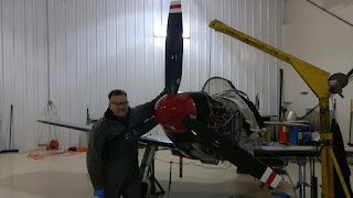
Most recently, the spinner was added and the engine was tested. Here is EZ giving his bird a "hug":
That is an incredible amount of work to accomplish in 5 months! Awesome job, EZ! We will all be looking forward to your reports from more test runs and taxi tests, soon!
6. Ray's Taxi Tests - In early Dec, Ray sent me the following email that pretty much outlines the current status of his airplane:
The aircraft is creeping towards being finished. I have the brakes fixed, the supercharger is trimmed for sea level takeoff power,( 29”hg and 2300rpm) and the right wing fuel leak is under a fix. If you want to get some shots of it running out on the taxiway, give me a heads up so I can get it ready.
The fuel fix may be done by the end of the week end, subject to the drying time of paint for the repair of the ethanol eaten paint under the wing. I will re-fuel the right wing after the fix and then do a test to see how much fuel is left after running the engine to starvation from the leading edge tanks. Once that is complete I will fill and measure the aft tanks and see how well they feed fuel and run them to empty. It’s getting time to get the air worthiness inspection out of the way. Ray
The fuel fix may be done by the end of the week end, subject to the drying time of paint for the repair of the ethanol eaten paint under the wing. I will re-fuel the right wing after the fix and then do a test to see how much fuel is left after running the engine to starvation from the leading edge tanks. Once that is complete I will fill and measure the aft tanks and see how well they feed fuel and run them to empty. It’s getting time to get the air worthiness inspection out of the way. Ray
I had a day off in LA between two trips on Dec 23rd and I was able to drive up to see Ray and take him up on his offer to get some shots of the airplane taxi tests. Not only did we get pictures of the airplane.....I got to start the plane and do the initial taxi runs! THANK YOU, RAY!!! It was an incredible experience for me. Truth be told, he had to let me sit in the front seat, because I (unfortunately) literally cannot fit in his back seat. (As a result of this, we are discussing options for changing the future Prowler design some to allow for a slightly wider cockpit).
The objectives for the day were to:
A. Put more time on the engine, while monitoring parameters to determine patterns and possibly detect any problems;
B. Test the brakes, tail wheel castering and overall taxi characteristics;
C. Monitor fuel consumption from individual tanks and see which tanks drew down fuel the fastest, the most total fuel consumed from each tank, etc.;
D. Look for general issues, problems or gripe items;
E. Take pictures, videos and have some fun.
Anyway, all-in-all, it was a great day. The tests went well and we were able to accomplish items from each of the areas listed above. We took a fair amount of pictures and videos during the taxi tests. I'm going to post a few here, but save the majority of them for a blog update that is dedicated just to these taxi tests. I'll post that update as soon as I can. But, for now, here are a few of pics and a video. Here's that Prowler Guy and Ray getting ready to fire up the plane:
One of the taxi runs:
Here's Ray giving Jim some pointers on getting into the back seat:Jim is one of Ray's good friends. He has helped Ray during several parts of his Prowler build: Here's an example:
That's Jim helping Ray flip his Center Wing Section over and onto the cockpit floor so that he can install the MLG (that was about 15 years ago!). Here's a video of that Prowler Guy having a blast:
7. The Latest From Bryce - Bryce is well underway working to restore the Red, White and Blue airplane that was the first production Prowler. He has decided to go with a different FWF solution and not use George's engine and reduction gear. So, he has one (pretty much) new, complete engine & PRSU setup for sale. He also has a the PSRU and the Accessory Gear Drive unit for sale that came off of a damaged engine. I will try to get pictures of these items to post. In the meantime, if anyone is interested in any of these items, please get in touch with me and I will put you in touch with Bryce.
8. An Update From Francis - I just received this update from Francis today:
Hello Todd,
The last two Saturdays, I have finished drilling the 3.2mm dia. rib [holes] and
fixing angle plates [to the main spar]. All are deburred and ready for alodine (I think the beginning of
January).And, I have install[ed] the pitot brackets or [and] pylon mounts (I forgot). And, I have [aslo] made a special pliers or clamp for spar U fit.That's all. I wish you good festivities end of year!
Here are the pics that he sent with the update. I believe that these two pics show where they have added the angle brackets for the pylon attachment pads just outboard of the wing junction:
An overall photo of the progress of the main wing (center section on the left and the two outboard sections in the foreground):
This is the plier clamp he mentioned in the email. That looks like a great idea for holding the spar cap strips (or other parts) down tightly in the bottom of the channel:
That's a very ingenious design! I might have to make one of those for myself! Hey, what's that brown bottle in the upper right hand corner? Maybe some special solvent, or lubricant? Ha! Thank you very much for the information and pics to update us on your progress, Francis. I really appreciate you taking the time to keep us all informed.
Well, that's a wrap for now. It's Dec 27th now and I will publish this update soon. It took me a couple days longer than I'd hoped to get this update done, but the job that pays the bills has really been getting in the way. I hope everyone had a Merry Christmas, or a happy whichever holiday you celebrate this year. See you soon, in 2016.


