Welcome to the last Prowler Blog post for 2016. I hope you all have had a happy holiday season. The day job has been busy for me this holiday season. But, I did manage to get a few good groups of days off in early Nov and early Dec that allowed me to make one last big push on the 400 ton press. I also have a couple of really nice builder updates from the past few months. Here's the list for this update:
Prowler Items
1. 400 Ton Press Hydraulic Unit
2. Builder Updates:
2.A. Francis - Continues His Fantastic Progress
2.B. Ray - Getting Ready For FAA Inspection
2.C. Ernest - Getting Ready For EAA 2017!
Non-Prowler
3. EAA Flight Simulator Made Successful Debut
I don't have too many items for this update. That's probably a good thing, as I don't have a lot of time to get this update posted! Before I start this update, I wanted to reflect a little on this year and highlight the bigger accomplishment for Prowler Aviation this year.
The year 2016 started out in a big way with the movement of 2 Prowler kits. First, was the sale of Kit #6 to Eric in Montreal. That was the kit that Byran and I saved from the recycling bin 2 years earlier. We cleaned it up, completed it, boxed it, advertised it in several places, and eventually found a new home for it! The second was the sale of kit #15 from Dr. Peper in TX to Frank "Pancho" Kinkaid also in TX. It's great to have 2 new owner/builders onboard!
Throughout the rest of the year, the 400 ton press repairs pretty much dominated my Prowler time and attention. The year started off pretty well, when I got the cylinder back from the machine shop. But, the ram rebuild took months longer than I'd anticipated. In the end, I got the press back together and tested in early summer, just before leaving home for weeks to work and head to AirVenture. Later, in this update, you'll see I made one last push lately to get the press going. It's real close to done.
Also this year, I got my 1st opportunity to visit EZ in the Seattle area. He picked my up at my hotel while on a layover in SEA and we went to see his Prowler. He'd been working on it and repairing it for over a year - getting it up to the condition he wanted it to be in. When I was there, we discovered that his flap actuator assembly had gotten bent, and I went to work the next week to get his actuator repaired and back to him. It worked great and he's got his flaps working very well again. Overall, he's doing great work and is promising to have a Prowler at AirVenture next year in 2017. It's gonna be great!
At various times throughout the year, I got some good forward progress on several of the outstanding parts and assemblies that I need to complete kit #18 that is inhabiting my office over the shop. My new year's resolution for 2017 is going to be to focus on getting that kit completed and up for sale.
I also got a couple of AWESOME opportunities to get up to see Ray and drive his Prowler around in taxi tests. Thorough the years, Ray has offered such incredible support to me and given me so much inspiration to keep going with this whole Prowler project. It's times like getting into his airplane and taxiing it around the Camarillo airport that helps to keep me motivated and to keep me going in the pursuit to get this airplane back into some kind of limited production. I cannot thank you enough, Ray!
It's been a great year to watch the progress of Francis on his Prowler project and help him along the way with info or drawings. He is doing such a great job and is always happy and willing to share all of his photos and information about his project. It's great to have his progress to report on during my blog updates. Thank you for sharing, Francis. I really appreciate it.
Overall, while still small, it's been a busy, productive and exciting year for the Prowler community. I'm looking forward to growing the community more in the coming years, as I eventually get some production going.
And, now, on with the show. Here's the latest update.
Prowler Items
1. 400 Ton Press Hydraulic Unit - When dad and I first got the 400 ton press re-configured and put together, we needed a hydraulic unit to test the press with. I had an old Williams Model 30 unit kicking around that came with all the stuff that I got from George. Early on, dad and I made up a mounting frame and bought a new 3 hp motor for it and installed it on the wooden platen press that I had gotten from George. Dad made up a nice sliding mount for the motor to tighten the belt and we made a nice mounting system for the hydraulic unit. It's all on a base that will collect any oil that leaks. You can see it here:

But, to run the 400 ton press, I needed a hydraulic unit capable of 2500psi. I was able to look up the company that bought the Williams company and got some useful info on this Model 30 hydraulic unit. The engineer there told me that the pump was capable of 5000psi at approximately 10gals/min. He told me how to re-set the pump output pressure and we took the unit apart and got it set for the correct pressure. I did the calculations to determine how much volume of oil that I would need to have to make the 400 ton press cycle the amount I needed. We needed to increase the volume of oil that the tank could hold, so dad and I came up with a speedy solution to simply add another reservoir alongside the Model 30 tank. I did some additional plumbing and we came up with this temporary unit we could use to test the press:

However, now that I have the press rebuilt and I have not spared any expense to make it right, I also wanted a hydraulic unit that would work well, look good, and fit on top of the press - to save space. My two basic options were to: A) Build a new hydraulic unit from scratch; or, B) remodel/improve the Williams unit. After some thought, measuring, and calculations, I decided that the old Williams Model 30 could be made to do the job. So, the first thing I did was take the pump back out of the unit:


As chance would have it, I found a gent that was advertising a Baldor single phase 5 hp motor on Craigslist. He said that it had a 1.125" shaft size. I pulled the pulley off of the 3 hp motor and measured it......it was also a 1.125" shaft size. That'd be convenient! I decided to go for it and I bought the motor. Turns out, the motors both had the same shaft height above the mounts:
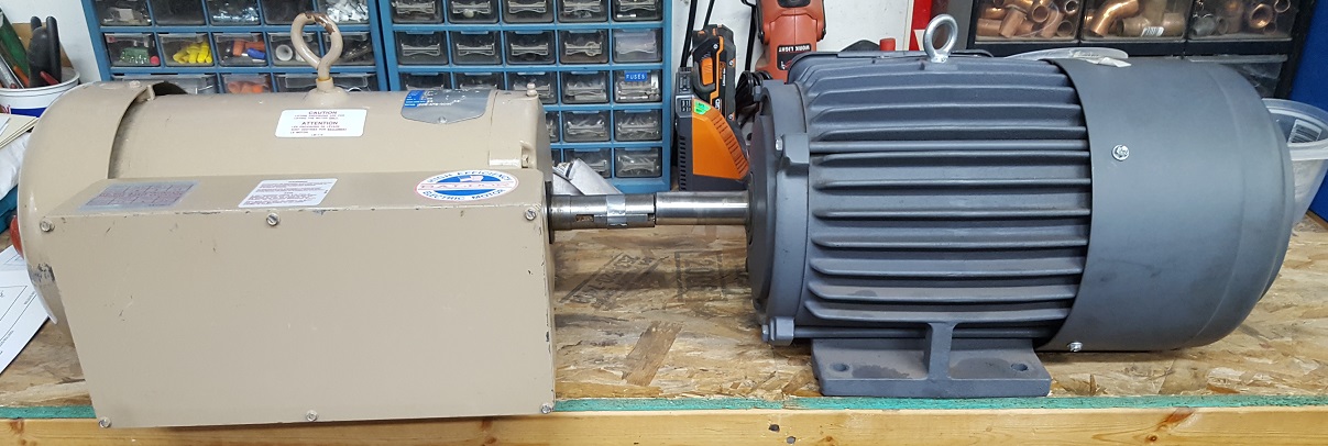


When initially testing the new press, it was literally taking 15mins for the press ram to move from the up position to the full down position. I figured it was the restriction of the small diameter hydraulic hoses and fittings that was preventing the oil from freely flowing back into the reservoir. I hoped that by providing a minimum diameter of 1" from the press cylinder all the way to the reservoir - the time would decrease by a lot. (Turns out, this was correct - the time to cycle the press down is now 35 seconds).
Here is a pic of the hydraulic unit with the motor installed, the pump installed in the tank, and some of the plumbing completed. Note the red low pressure, 1" hydraulic hose return to the top of the tank:


A. Turn the power on;
B. Make sure the dump valve is closed.
C. Place the die and blank.
D. Pull the valve control handle to raise the bolster;
(pressurizes the cylinder and raises the ram)
E. After the pressure builds (and the part is formed) release the valve;
F. Open the dump valve;
G. When the bolster drops - remove the die and the formed part.
After getting the press working, it was time to start moving it towards its new home spot in the shop. To do this, I used the mobile base that I had designed and built for the press. All it takes is a 3 ton floor jack (to lift the yoke in the back) and a small cable hoist to give it a gentle pull. It was a little too much for me to just push it by myself, but two guys might be able to push it by hand. Anyway, I was on my own for this move, so I used a cable hoist dogged off to some anchors in the floor:

The very last thing to do with this press is find a block of rubber for it. Actually, urethane. I'm not having a lot of luck finding a solution that I like at a cost that I like. More to follow in this in a future update.
2. Builder Updates:
2.A. Francis - Continues His Fantastic Progress -
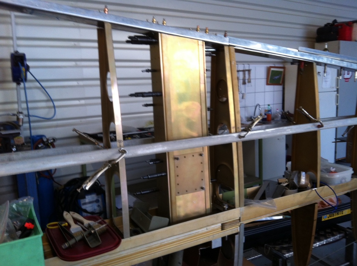
Francis has really been "knocking it out of the park" lately and making fantastic progress on his Prowler. Here are some of the recent pics he has sent me of the work he's been doing. In no particular order is:
Torque box access holes:


2.B. Ray - Getting Ready For FAA Inspection - Ray currently has his PSRU apart for some final work and inspection. As soon as it is back together, he has Dave Prizio lined up to do the Airworthiness Inspection for his experimental certificate.
In the meantime, he's also been working on modifying some of his MAC servos to improve the response time. He's been experimenting with various DC-DC converters. By putting higher DC voltages on his supercharger wastegate, he can get it to change positions (and power outputs) a little quicker. I expect that my next blog update in 2017 I will be covering the results of Ray's airworthiness inspection. More to follow.
2.C. Ernest - Getting Ready For EAA 2017! - EZ is making more excellent progress on getting his Prowler ready to take flight again. I recently got to see him again during an overnight in SEA. Here he is working on installation of the coil selector diodes for each spark plug:


Non-Prowler
3. EAA Flight Simulator Made Successful Debut - Mr. Bill was the man who had the idea for making a mobile simulator that I've been working on. Well, Mr. Bill decided that he really wanted to have the mobile simulator exhibited at the local version of the Maker's Faire. I really didn't know what that was all about.....but I did know that I wanted to get this project closer to the finish line and off my plate of things to do. So, I started to make one last push to get this project across the finish line. Here is the power outlet installation in the engine bay of the sim to power the computer, screens and fans:


Here is the simulator being set up in the Civic Auditorium for the Maker's Faire by yours truly and Jeff (the computer IT specialist that built the computer for the simulator). We're getting everything set up for the show:


OK. That's all for this update. Thank you all for your interest in Prowler Aviation. I hope you had a great 2016. I look forward to seeing you all again next year.


