Friday, November 23, 2012

Happy Thanksgiving From Prowler Aviation

Hello Again,
Thanks for stopping by to watch the progress and Happy Thanksgiving (yesterday - sorry it's a little late).  I hope you all had a great holiday.  It's been raining this past 4 days that I had off of work, so no concrete work this trip home.  I did get into the shop a little and tied up a few loose ends with the plane building.  I also figured I could use the time to work on a blog update.  In addition, last week I had the opportunity to visit Ray for a few days and we ran his airplane both days while doing some troubleshooting.  So, I don't have a lot to include in this update, but here's what I got:
1.  Retaining Wall Project Is Rained Out
2.  Finishing Some Wing Jig Work
3.  Rib Smasher Hydraulic System
4.  Running Ray's Airplane
5.  Bryan's  Latest Update
6.  Fracis and Robert (Kit #11) Update

1. Retaining Wall Project Is Rained Out - Well, it's now officially winter weather in northern California.  When it rains more than 2 days in a row, it's winter!  That means that the ground turns to "Marshmallow Fluff" and you cannot walk on it or work with it.  If you don't have it packed down and graveled by now - you will pretty much have to wait for spring for it to dry out and become manageable again.  Before the rains started though, I did get most of the first tier of wall poured.  Here's what it looked like then with one section of cap put on:
Then, I got 2 more sections of cap poured on it.  Here's the cap poured on the south end of the wall:
In the second tier phase, I'll be going up with another 18 inches all along the back of the 1st tier cap.  Eventually, it will look like this cross section  along the entire retaining wall:
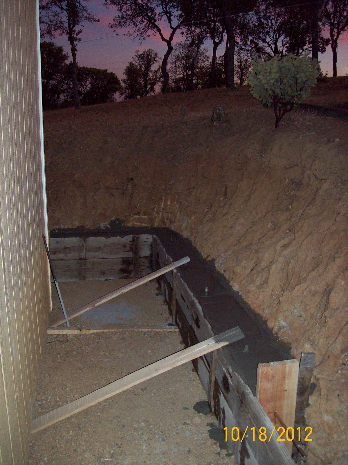
I also got 3 more sections of cap cut out of the bank and formed up, but couldn't get it poured before the rain started.  Here's what that currently looks like (notice the mud that has already sloughed off the side of the hill behind the forms):
I also managed to get (finally) the rain gutters and downspouts on the roof in the back of the shop.  Here's that:
 So, that's what's been keeping me tired and sore for the past several weeks!  However, since the rains are now upon us, I moved back inside and started to get a few airplane related things done again.  I had to walk around and stare at things for a while to help me remember where I was at with most of these projects (before I dropped everything to work on retaining walls).

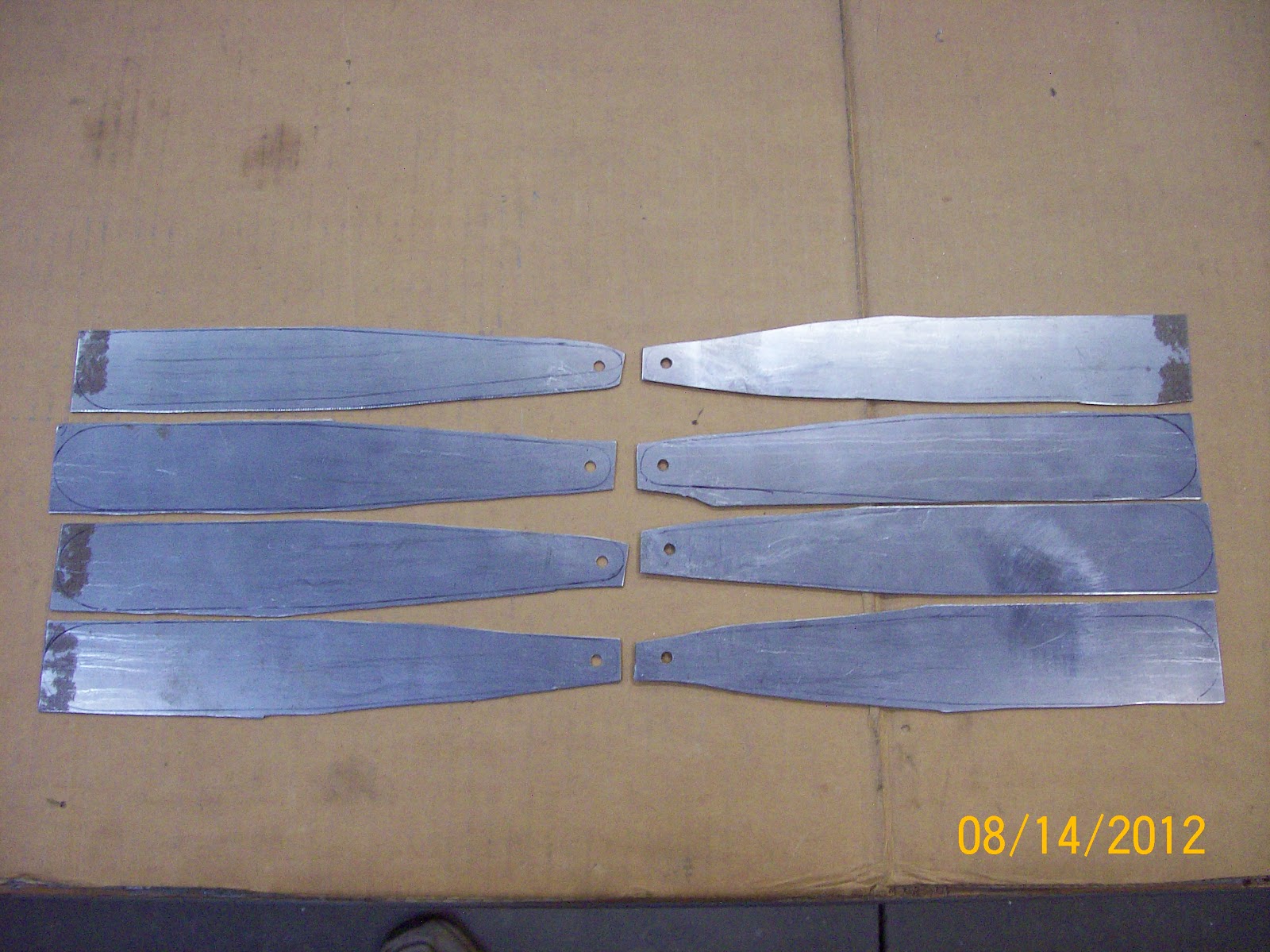
2. Finishing Some Wing Jig Work - When I was fabricating the wing jig, I left some work to be done with the posts.  Namely, fabricating some "L" shaped reinforcing plates and putting them in place on the posts.  Here's the plates that I fabricated from 1/4" steel plate:
These just help stiffen the 90 corner from the jig feet to the posts.  Here is a pic showing where they will go (approximately):
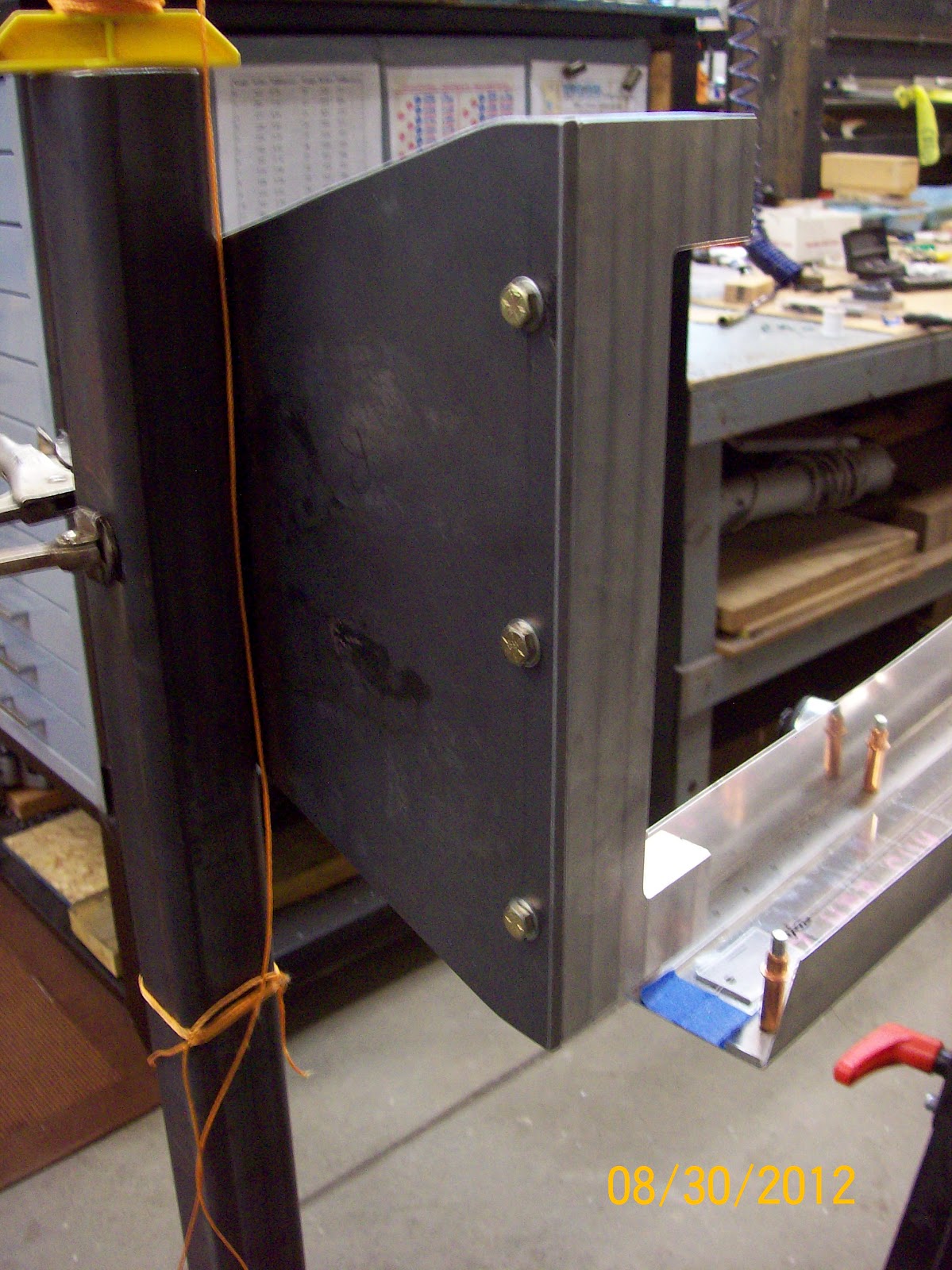
On the wing jig there are supporting posts in three places: 1) at the wing tips;  2) at the wing junctions; and  3) in each MLG wheel well.  On my wing jig the wing tip posts and the wing junction posts are welded in place.  But, the post in the MLG wheel wells have to be made removable so that you can test the MLG once it is installed into the wing.  Here you can see the center posts with the plates drilled, tapped and bolted on (center) and the wing junction posts with the plates welded in place (front and back):
Finally, one more small job done that has been "hanging fire" for a while.  These plates really made a big difference how rigid the wing jig is now, compared to without them.  Excellent.  On to the next job(s).

3. Rib Smasher Hydraulic System - It's time to get going on the hydraulic system for the 100 ton rib smasher.  I started by spending an evening trying to figure out the most simple way to plumb all the parts that I laid out in this system schematic that I posted in the last update:
Here is the hand-drawn version of what I came up with:
The check valves come as double ended 1/4" MPT (Male Pipe Thread), so they will just screw into each of the 4 ports on their respective manifolds.  Then, the two TEE's will have female connections on all 3 sides, except that one of the opposing sides will have a swivel fitting.  That one swivel will allow everything to thread together and make one complete rigid unit (2 manifolds, 2 TEE's, and 4 check valves) to mount onto the side of the press between the reservoir and the pump.  (You can see the tank and pump mounted to the press as you read further below).

I decided that the most economical way to get this system built would be to order some parts and make the rest.  The parts to order are: five 1/4" hoses, 2 adapter fittings, two 1/4" TEE fittings and four 1/4" check valves.   The next morning I headed out to the local hydraulics shop and ordered everything but the check valves.  For those I went online and ordered them from Motion Industries - I'd previously researched them online.  The items I will fabricate include a hydraulic reservoir and 3 manifolds. 

Next up was getting a start on the manual pump.  The manual pump that I bought online was apparently a project that someone started, but never finished.  One side of the pump had a 1/4"x2" angle iron that was used to mount the pump.  But the opposite side only had a "floating" plate that wasn't secured in any way.  So, for starters, I fabricated 2 angle iron clips to weld to the existing angle iron side of the pump to allow for easier mounting to the side of my press.  Then, I fabricated 2 pieces of flat steel with nuts welded to one side to mount on the back side of the pump that would hold the position of the plate on the other side.  After that, I aligned the "floating" plate and welded the ends of the flat steel to the far side plate to keep it in position and make it not "floating."  Now, two short 1/4" bolts hold the whole assembly together.  It worked well, check it out:
 Here is the unit installed on the side of the press:
 From there, I moved on to the fabrication of the reservoir.  I started with a piece of 3"x4" steel tube that I got for nothing from a local fab shop.  It needed some cleaning up, but the price was right.  I cut off two pieces that were 12" long each.  The first one looked like this:
Then I cut one side off of each of the two pieces so that it looked like this:
 Then I joined the two halves and filled in the holes to make the main body of the tank:
Next, I fab'ed the bottom plate and a 1/4" female pipe bung.  Here it is just before welding:
 Later, I fab'ed the top with a fill hole and added another 1/4" return line bung on one side near the top.  Here's the tank after welding it all up:
This was my first experience with building a liquid tight tank.  I figured that I should probably give it a leak test before mounting it.  Good thing I did!  When I first filled the thing with water - it leaked like a sieve.  It turned out to be quite a task in repetitively filling, checking, grinding, welding (many times) to find all the hairline cracks and get them patched up.  I am (admittedly) not the best welder, but I didn't think welding would leave so many hidden cracks.  I finally got it sealed up and I left it filled with water over nite to make sure that there weren't any slow leaks. It passed, eventually.   Here's the tank during final leak testing. 
And, here is the tank mounted to the side of the hydraulic press:
 Now, I am waiting for the parts to show up from the local hydraulics shop and the online order.  In a few weeks I should be able to get some time in the shop and start putting all the pieces of the hydraulics system put together. 

Schedule Sidebar - It will be a while before I get back into the shop.  I'm working the day job almost steadily until the 2nd week in Dec.  Then, my first 4 days off in Dec I'm going to take a truck and trailer down to Salinas and help Chuck's wife (Nancy) dispose of the stuff in Chuck's hangar.  Nancy has finally gotten the myriad necessary things done after Chuck's death and is now ready to tackle cleaning out the hangar. 
Several folks have spoken up and want to buy many of the tools and machines that Chuck had in the hangar.  I'm going to help her get the big things down, out of the hangar and delivered to the next owners - as needed.  Then, when everything is gone that everyone has spoken for, I'm going to purchase all that remains in the hangar from her.  It will be a lot of hardware, fittings, small hand tools, sheets of metal, shelves, etc., etc.  I will eventually be able to use all of that stuff in the Prowler business, so I'll load it all up and take it back to the shop.  And, it helps Nancy out so that she can turn the hangar back over to the city.  That project will keep me busy and I'll be "building the company" (so to speak), but not directly working on the airplane for a while.

4. Running Ray's Airplane - I was really fortunate to have a few days down in LA "on call" without having to actually fly and made it out to see Ray and his airplane again.  His wife was out of the county on a trip and we took advantage of the opportunity to hang out, talk Prowlers, and burn some gas with his airplane.  I took several videos of the engine runs, but my camera video lacks great quality.  Also, you'll see that my camera strobes the prop and makes it look like it's standing still, but it is really running at 62.5% of engine speed.

STARTING VIDEO - In the starting video you will hear the airplane start and then die.  Ray says "This is what it does."  What he is referring to is that the engine is not (currently) idling very well at all.  The fuel control below about 1000 rpm is very unstable and non-linear.  The engine runs very rough below about 750 rpm (if at all).  The engine will start to die if you pull the throttle back much below 700 rpm.  You will hear that a lot through all of these videos.  When it's starting to die, you can try to tease a little more throttle in, and nothing will happen.  Then you try a little more, and nothing happens.  Then a little more, and nothing happens.  Then, you move the throttle just a bit and the engine will catch again and surge straight to 1200-1500 rpm.  Here's the aircraft starting:
There is a temporary aux fuel tank that is sitting on the ground (behind the RH main) that is tied into his fuel system in the wing.  Ray has it set up so that his fuel boost pump circuit runs the fuel pump that is tied to this aux fuel tank.  The fuel line from this temporary aux tank feeds into the same place that his main tanks feed into his normal fuel system.

WARM-UP VIDEO - The engine takes a while to warm up even on a fairly warm day in Ray's side alley.  Of course, the cowlings are off now, which helps keep the engine cool.  After about 3-5 mins of idle at or above 1000 rpm the water temp starts to rise.  Then about 10 mins in, the oil temp starts to come off the peg and eventually stabilizes around 140 deg.  In this video you will hear the engine spin down like it is gonna die, then it surges back up to high idle.  The fuel control technician thinks that the idle section of the fuel control head may have to have the idle springs, balls and diaphragms replaced in the system.  Right now, Ray is waiting to hear from the technician before he pulls the unit off and sends it back to the company to do this work.  Here is the engine running during warm-up:

CYCLING THE PROP VIDEO - Once the engine is warmed up, it will idle better at (and below) 1000 rpm.  We could get it to idle (rough idle) at about 750 rpm once it warmed up.  Then Ray began cycling the prop to warm up the hub and see what the effect was on engine oil pressure.  The prop control system seems to function nominally.  The change in rpm during this video is only due to the prop cycling from low pitch to high pitch and then back to low pitch.  These were all done at about 1000-1100 rpm. 

If you look closely the prop governor is located toward the back of the engine, just above two thick white ground wires.  As Ray is cycling the prop, you will see the prop control lever on the top of the governor (it lays on it's side) go downward (for the high pitch, low rpm setting) and the engine rpm will start to drop.  Then it will go back upward (for low pitch, high rpm setting) and the engine rpm will pick back up.  It takes a while for the rpm to drop on the first cycle, remember the oil in the prop control system is still pretty cool.  Then on the subsequent cycle, the rpm drop is much quicker.   Here is the video of cycling the prop:

HIGHER POWER RUN VIDEO -  In this video, the engine is already warm and Ray is starting again after a short shut down to chat about some observations.  After the engine starts, he runs it at a higher rpm for a while (about 1500rpm and 15" MP).  We found that when the engine speed is above about 1100 rpm, the throttle control and the engine response is pretty linear - meaning that if you advance the throttle a little, you will get a little increase in the engine rpm, etc.

This engine is powerful!  I didn't get it on video, but on one start the engine surged pretty harshly and the prop wash literally blew the gates open behind the airplane (you can see the gates on the last video).  The gates are steel framed and wood covered.  The prop wash bent a 1/2" steel pin that goes thru the steel frame and into the concrete drive to hold the gate shut!!  I began to imagine holding the stick behind that much power in the air.  Should be fun - someday.  Here is the start and a higher power run:

VIDEO VIEW FROM INSIDE - Here's some video from over Ray's shoulder while he's testing the LH and RH ignition systems.  The Dynon's are not on in this video (he turned them on later), so all you see is a reflection in the top screen.  The engine tach is on the upper right side and you can see it's pretty steady on about 1100 rpm.  You will see Ray changing the ignition from both, to LH to RH and back on the lower right side. I'm not sure what the black button is that Ray pushes in the video - I'll have to ask him the next time we chat.

He has installed UMA gauges for all his engine parameters.  The lower row of gauges on the RH side are (from L to R):  Oil Press, Oil Temp, Water Temp, and then LH and RH fuel quantity.  Between the LH and RH fuel quantities is a switch to switch the fuel quantity indicators from the aft main tanks to the forward tanks in each outboard wing section.  Above the RH fuel quantity gauge is the Aux fuel quantity gauge (but you can't see it in the video as the canopy handle blocks it out).  All of them are currently not hooked up and showing off scale above full.

Then, above the LH fuel quantity is the the Fuel Flow gauge.  It used to be Fuel Press, but Ray replaced it.  The fuel control technician recommended the fuel flow, as having fuel flow indications will help them map the engine and finish the set-up of the fuel control system.  It's a very handy gauge to have!  The small UMA gauge above those two is the alternator/battery volts.  Then, the larger instruments to the left of that is the Engine RPM (above) and MP (below).  Here is a view from the inside:

FRONT VIEW VIDEO - I took some video off of the tripod, so it's not as steady and I move around.  You can see the gate that I mentioned earlier in the background.  Just forward of the firewall you can see the intake for the supercharger.  That mates up to a NACA scoop on the engine cowling when it is installed.  And, here is a view from the front:

It turned out to be pretty productive time doing these engine runs.  Fortunately, Ray was able to arrange to get the local technician for the fuel control system out to see the airplane run.  I got to jump in and run the plane while Ray and the technician discussed what was happening.  As I mentioned earlier, he has decided that there is something that needs replacing or rebuilding in the idle control section of the fuel controller. 

Before the technician got out to work with us, Ray wanted to check his advance on the ignition systems to make sure that they were working correctly and not something that could be compounding the problem.  Here's a pic I took when we were putting the RH ignition back together:
Update - since I wrote the information above about running Ray's airplane, he has updated me a couple of times.  He has now sorted out the rough running ignition.  Turns out that there was a missing bushing on the right distributor that was allowing the ignition to get much to retarded at low idle speeds.  He's replace the bushings in the distributor and reduced the high rpm advance to about 27-28 degrees BTDC.  He reports that the stable idle speed has dropped about 200 more rpm and there now is no noticeable difference between the L and R ignitions.

He also has taken his hydraulic pump out and is working on reducing the output pressure that the pump puts out.  It was making a lot more pressure than was necessary to swing the gear, and he wants to get the pressure output more closely matched to what is actually needed to operate the gear.

The fuel control body will come off of the airplane soon to send to the manufacture to get rebuilt and adjusted for this application.  While that is happening, Ray is going to begin prepping the aircraft for paint and coordinate with the fella that is going to paint the airplane.  They're going to work out what paint, the paint scheme, and logistics to get the job done.  More to follow as Ray approaches his first flight sometime next spring.  Nice work Ray!

5. Bryan's Latest Update - I am constantly astonished at how fast Bryan continually makes progress on his airplane.  His latest creation was a forward baggage compartment in his Prowler.  Since he is building his airplane around a diesel engine option, it provides him with some opportunities to do some things that the typical V8 engine project will not allow.  The two most notable of these are:
1.)  The ProwlerD only uses one wing radiator for water cooling, the other is used for oil cooling.
2.)  Because diesel engine fuel consumption is so much lower than gas, Bryan doesn't need nearly the same amount of fuel capacity as a conventional Prowler.  That alleviates the need to have an aux fuel tank in front of the instrument panel, like the conventional Prowler does.

Since Bryan doesn't need to have his aux tank in the fuselage (his is in one of his main inner wing tanks) - he has that room available for a good size baggage compartment up there.  That's important because he significantly reduced the baggage compartment behind the cockpit by placing the first aft fuselage former at a reclined angle.  He was able to provide quite a bit more room in the aft seat in the cockpit by reclining the back of the cockpit, but the trade-off was less baggage space, until now:
Nice metal work Bryan!  That makes a really nice baggage compartment space.  In addition to reclining the aft wall of the cockpit, Bryan added "cut-outs" in the sides of the cockpit where the aft pilot's legs will be when seated with the feet in the foot wells.  The will significantly increase the room near the forward pilot's hips where the aft pilot's legs normally "squeeze in there."  This was a very crafty solution to that problem.  Here' a look:
Here is a look at the latest revision of his instrument panel plan:
In addition, Bryan got his hydraulic unit back from the manufacturer and they didn't find anything out of specs with it.  So, it appears like the system is being "resistant" to a thorough bleeding.  More on that as it develops.

6. Fracis and Robert (Kit #11) Update -   I have exchanged a few emails with Francis recently.  You may remember that he and Robert are the new owners of Kit #11 that they purchased from Nicolas in France.  Here is one of the emails from Francis (with my changes in [ ] ).

Hello Todd, some news of (Kit) n°11
The "hangar" is finish but no electricity (7weeks that we wait) it's long!!  We need electricity for the jig and air compressor!

I have finaly find rivets in -7 for deriveting [re-riveting?] the spar (some rivets are not very nice).


For alodine I find some alodine in "gel"condition (for the main part it' s perhaps a solution for you).  When i make [built] my Skyote, there have a big spool [pool?] of alodine at my job (Air France) 6foot wide, 6 foot deep and 20feet long! Same one for deoxidine for the "hydraulique" aluminium tube of jet liner. 
But, they discard it!  So I find alodine in gel condition!

The french law for experimental autorized may be more than 200hp if we dont class in voltige.  We have bought a 200hp oldsmobile engine whith reduction unit and rear accessory box.  Do you now if there are bolt on on 350 chevy or rodeck?

Sorry for my english!
Francis


Thanks for the update Francis.  Please keep us posted on your progress.

That's it for this update.  I want to get it published and it's already a day later than I'd planned.  Thanks again, as always for stopping in to see how things are going here at Prowler Aviation.  I'll plan on one more update before the end of the year.  Until then, I hope you all have a very happy holiday season.

Sunday, November 4, 2012

Ray Has Started His Prowler!

Hello Everyone,

Thanks for stopping to see what's going on @ Prowler Aviation.  I don't have a lot to report this update, but a few goods things are happening and I am trying to keep my promise to update more often.  So, in this update:

1.  Ray has started his Prowler
2.  Bryan's Build Update
3.  Building More Retaining Wall(s)
4.  Start on the Low Pressure High Volume Hydraulic Pump
5.  Getting Materials & Tools For Tip Ribs
6.  Also Looking Ahead To Spar Completion


1. Ray has started his Prowler - Ray started his airplane for the first time on Oct 13th.  He reports having to sort through some issues, but the engine is running fairly good.  Here is a video he sent me:
Initially, the oil pressure was high and temperature was low (as expected). But, in a normal manner the oil temp came up to about 140 deg F and the oil pressure reached a steady state of about 30-35psi.  His coolant temp took a while to come up, indicating good cooling in the radiators - even with only prop wash through the radiators.
The biggest bug of the engine runs is the fussy fuel control.  The system seems to be very sensitive to throttle changes and the mixture has to be adjusted constantly for every throttle movement to keep the engine running.  Ray has contacted the fuel injection manufacturer and is now working with a representative to get the system set up correctly.  The first issue is to add a fuel-flow meter system to the airplane.  Apparently, in order to properly map the fuel to air, the system has to have a fairly accurate fuel-flow indication.
After the engine runs, as not unexpected, he found a few small leaks that have been corrected.  He also found that the prop was not completely snug down to the prop flange on the reduction gear cause by a slightly over-sized o-ring.  So, that will be corrected when the prop gets removed soon for other work that will need to be done.
Congratulations Ray!!! That is a major milestone in your project.  You are going to have one awesome (running / flying) aircraft soon!

2. Bryan's Build Update - Just a quick update from Bryan.  The hydraulic pump that Bryan and I were having a problem bleeding has been returned to the manufacturer.  They are still working on the pump/motor.  in the meanwhile, Bryan has installed the roll bar (AKA the windscreen frame). Here's a pic:
Great work Bryan!

3. Building More Retaining Wall(s) - Since building my shop, I've been ignoring a problem with the steep bank that was cut into the hill where the building pad was cut.  Here's a composite pic of what it looked like after the pad was cut and before the slab was poured:
If you click on the pic, you will see the bank in the back left corner that was created when the building pad was cut into the hill.  After the shop was built, there was about 36" of space between the back wall of the shop and the base of the bank.  Below is a pic of what the area behind the shop looked like when I was installing the drain pipe and gravel (as I built the shop).  But, over the past 6 years, the weather has caused the bank to erode down and build up against the back of the shop. This spring, the mud had finally built up until it was touching (actually above the bottom of) the siding. So, it's time to fix the problem and build a retaining wall:
Here is what the same area looked like recently after I pulled the drain pipe back out, cleaned out the gravel and mud, then started to cut into the bank more to provide space for a poured concrete wall:
 Here's part of the first 20 feet of the 1st tier of the wall after forming.  I'm actually using the same form boards that I used to form the slab for the shop.  I doubled them up one on top of another and then scabbed them together to make an 18" high form section that is 16ft long:
The first pour was 20 feet total, 10 feet on the south wall and 10 feet on the west wall.  Here's the 10 feet of west wall (looking south) - notice the 2"x8" dam to stop the pour @ 10ft from the corner:
As you can tell, this was the end of a long day.  I just got this first 20 feet in the corner mixed and poured before sunset.  Here's the 10 feet of south wall (looking west):
Because this is such a long wall, and it's such a tight area to get into - I've been using my concrete mixer and just buying bags of sack-crete to build the wall.  I would spend too much for forming materials to try to form the entire wall up at one time and then get premixed concrete trucked in.  Plus, I'd have to get a concrete pump truck that would be more costly than the concrete itself.  So, I've elected to just do it myself, on the cheap.  Here's the mixing station with a pallet of covered concrete bags:
Here's the second 20feet of wall completed:
Here is the 3rd section of the wall poured and forms removed:
The end of this wall will also get an angled section attached to it that is similar to the section in the picture below.   And, here's is that other angled 10ft section of wall on the south end of the shop that is formed and ready to pour:
After this section and the other angled 10 ft section are poured, I will have the first tier completed.  Then next order of business will be getting (finally) rain gutters on roof in the back of the shop.  After that,  I'm going to pour a thin sidewalk behind the shop in the area between the shop foundation and the bottom of the newly completed wall.  That area gets just soupy and muddy in the rainy winters and grows weeds in the spring/summer - so I'm going to form it up and pour a thin sidewalk back there to keep things neat and clean.
In addition to all of this work, I also got 4 loads of fill dropped off to help expand my shop driveway on the north side of the shop.  This fill will settle over the wet winter time and provide a more permanent place to park the RV next summer (and beyond).  It will also provide back-fill for the "Great Wall of Prowler" as I continue to work on it (probably next spring).  Here's a pic.  You can see the partially complete north end of the great wall in the lower right hand corner:
Here's a pic of the same area from below - you can see the need for the wall from this view:
As you can probably tell, these retaining wall projects have been taking a lot of my time (and money) lately.  So, I haven't gotten a lot done with the airplane or the company.  But, it is on my mind. While I'm mixing concrete and I am using the time help solve some problems with wing spar and hydraulics that are coming up.  Then I use the down time (while I'm resting my aching back) to locate and order parts or pick up supplies, etc.

4. Start on the Low Pressure High Volume Hydraulic Pump -  I have been taking the opportunity [while NOT working on retaining wall(s)] to look for and buy parts for the hydraulic system I need to assemble for the pseudo-hydro forming press.  I was searching for a Low Pressure/High Volume (LP/HV) pump solution to add to the existing system.  I looked into electric motor driven systems, but they are usually expensive and designed to run full time.  I don't need that for this application.  I looked at 12Vdc hydraulic units used on dump trailers, etc.  But, they don't come up on eBay or Craigslist often - unless they're worn out or broken.  Also, they are not real high volume and new, they want $300-400 for the units.  Then, I came across an eBay add for a manual pump made from a Parker hydraulic double acting ram.  I liked that this idea was simple, fairly fast, and not too expensive ($50).  Here's a picture of the pump as it was in the auction ad:
This is what the same pump looks like stripped apart on the workbench:
I needed to take it apart to check that the seals were good, and to confirm that I can use it as a double acting pump.  It turns out that I can do it, but I will have to machine a few more ports into the cylinder end caps similar to the 90deg one that you see on the right side of the free end cap (closest to the black handle grip).  This piston has a 1" bore and a 2" stroke.  So, it will move 4 cu.in. of hydraulic fluid in one (double acting) stroke.  Doing the math on the ram, it will take about 12-15 strokes to move the ram into crushing position (approx. 2-1/2" inches up).  To me, that seems reasonable, reliable and controllable.  Here is the overall schematic that I am planning for the hydraulics system for the press:
This system will provide me with a quick way to get the ram moved up into position using a manual hydraulic pump.  Once I use the manual pump to get the ram and the lower press box into position, both the LP Isolation valves (both are 10,000psi valves) are closed.  Once both of those valves are closed, I will use the 10,000psi HP (air over hydraulics) pump to do the actual metal forming (rib smashing).  This design will also require 4 check valves to sequence the movement of hydraulic fluid from the reservoir to the ram.  If you look at the diagram you can see that as the handle of the pump moves one direction, one of the inlet check valves is opening to let fluid into one side of the piston and the outlet check valve is open on the other side of the piston to allow the fluid to move toward the piston.  (BTW - the single acting version of this is EXACTLY the same as what you have in any hydraulic bottle jack.  The only difference is that the check valves are integral into the base of the jack where you can't see them - but they're there!).

Here's how I envision the final system will work:
1.   Place die, blank, and rubber in the press box.
2.   Ensure LP Return Valve is closed.
3.   Ensure LP Supply Valve is open.
4.   Use manual LP/HV pump until rubber partially smashed.
5.   Close the LP Supply valve.
6.   Mark position of press box (vertical height).
7.   Step on the HP/LV air-over-hydraulics pump and press part.
8.   Step on the HP/LV pump pressure release and lower press box.
9.   Stop at same place marked in step 6.
10.  Open LP Return valve and lower press box to bottom.
11.  Remove rubber, part & die.

Here are the the 10,000psi isolation valves I and a short hydraulic hose that I bought so far:
The only parts I still need to finish the system are the 4 check valves, a few 1/4" hoses, and various hydraulic fittings (reducers, 90 deg elbows, etc.).  Oh yeah, I will also need to either fabricate a new 5-port manifold or expand off of one of the 3 ports on the 3-port manifold that I have already made.  Not sure which way I will go on that one yet.  More to think about while I'm mixing concrete.

5. Tip Ribs - Getting Materials & Tools Lined Up -  I have also been using the time while I'm building retaining walls to gather up some tools and materials for getting the tip ribs made this winter.  Here is some of the planning data, in no particular order: 
1.  I've decided to start making my dies from aluminum (at least for the time being).  Every part that will need to be formed from a die will have to be made using this process and will have to have a new die made from AL.  I haven't even tried to count them all yet - I'm afraid to.
2.  I have all of the CAD drawings of all of the parts to be formed completed already and the profiles can be CAM'ed and sent to the Ganesh CNC mill fairly readily.
3.  The flanges on the blank (as they are being formed) cannot hit the bottom of the press box, so the aluminum plate that the die is fabricated from has to be a min of 1" thick.  The dies must also be made individually for each part and the same die CANNOT be used for the opposite handed part (in other words, the LH die cannot be used to make the RH parts, and vice-versa.)  This is due to two reasons:
3.A. The sides of the dies have to have a rather large radius on the top edge to prevent the blank from cracking during forming, and:
3.B.  The sides of the dies have to be undercut by 9-10 degrees to allow for spring back during forming.  Here's a pic of what that will look like:
4.  The dies will have to be made using the CNC Knee Mill - in 3 separate steps:
4.A.  Cut the die profile (what you see looking from the top down).  Here is a sample of the tip rib CAD drawing that I recently re-designed and will use to cut the tip rib dies.  The top profile in the pic below will be the one used to fabricate the basic shape of the tip rib die.  Looks like I will need aluminum plate that is at least 25" long and 3.5" high:
You may recall that I have decided to re-design the outboard tip rib to work in the new press.  This new truncated design prevents the thin trailing edge from causing problems in the pressing process and make the tip rib fit lengthwise into the press box.
 4.B.  Cut the 1/8" to 3/16" radius in the top edge of the die (using the same profile).  This can be done using standard off-the-shelf radius end mills.
4.C.  Cut the "under cut" to allow the flanges to be "over-bent" to allow for spring-back.  Here is the tool that I had specially made by a local tool-and-die maker ($125):
Here is what it will (sort-of) look like when this tool will be used to "under cut" the profile on the die:
5.  I found a place in Sacramento that sells surplus odds-n-ends pieces of aluminum plate.  Here are several pieces that I got recently in preparation for cutting some of these dies.  You might be able to see a black dashed line on the right side of the old tip rib pattern.  That is the approximate length that the new tip rib die will be:

6.  Also Looking Ahead To Spar Completion -  Once I have the spar installed into the jig, I will have to take it back out to do the corrosion proofing (chromate conversion process - AKA "Alodine").  You may recall from a  previous post this early this year that I spent quite a while researching the chromate conversion process [(see it here)  Item 3. - almost to the end of the post]. 

Here are the  parts of chromate conversion puzzle (readers digest version):

1.  You have to have an etchant to clean the aluminum thoroughly before applying the chromic acid (Alodine, Iridite, etc.).  In the link above I learned that this etchant can be made from 1/3 phosphoric acid (75%), 1/3 ethylene glycol, and 1/3 water.  This makes a 30% etchant solution that can then be diluted further, as needed, to clean the aluminum parts.  So far, I've found and purchased the phosphoric acid from Sierra Chemical Supply in Sacramento:
The chemical supply place didn't have the ethylene glycol in stock when I got the acid.  They reordered it and called a few days later to tell me that it is now in stock, so I'm looking for an opportunity to pick that up on a future trip to Sacramento.

2.  You need to have the chromic acid.  Here is the 10lbs pail of Iridite that I got from a chemical supply place in the LA area.  I ended up driving it home on a family trip - shipping is complicated because it is a hazmat (oxidizing) substance.  This dry powder gets mixed with water and each pound of dry Iridite makes 5-6 gallons of chromic acid for the chromate conversion (AKA "alodining").
3.  You need to have 2 big tanks to do the chromate conversion process to your parts.  The best thing to make the tanks out of would be PVC.  But, having specially made tanks big enough for the wing spar parts would be fairly expensive.  I'm planning on making two tanks from 2"x 4" lumber for the sides and a 2"x12" plank bottom.  Then this will be lined with a layer of felt and then double layers of 6-8 mil poly sheet.  Here's my initial idea:
All this material is readily available from Lowe's or Home Depot. The biggest parts of the spar to put in the tanks are the center section main spar shear web and the outboard wing spar channels.  The main center section spar shear web is essentially 96"x10".  The outboard spar channels are 85.5"x 6.5"x 2.5".  So, a tank that is 100"L x 11"W x 2"D should suffice.  Doing some quick math, filling the tank above (assuming a 100" length) to a depth of 1" will take 5 gallons.  The outboard spar channel will have to be done one side at a time and rolled over.  The rest of the parts are all flat and can be submerged in 1" of fluid.

4.  When you have all this mixed and set-up the process goes like this.  Dip a part in the etchant and let it sit until it is dull in appearance and when lifted out of the water the etchant runs clean off and doesn't "stick" anywhere on the part.  If it sticks, it goes back into the etchant for a while longer.  Once it's clean, the part comes out of the etchant and then gets thoroughly rinsed with water.  As, soon as it is rinsed it it placed into the chromic acid tank and soaked until the surface gets a yellowish to brownish appearance.  Then the part is removed, rinsed again with water and hanged to dry.  Repeat for all the parts.  There are lots of YouTube videos to watch on how to do this.

 That's all for this update.  Thanks for stopping by again to check on the progress here at Prowler Aviation. 

Saturday, September 29, 2012

Getting Back On The Horse

Hello Again Everyone.

Well, our kids are back in school and that pretty much signals the end of summer around our place.  I hope everyone had (or is still having) a great summer.  I didn't get a lot of Prowler work done in the past 3-4 months for a couple of reasons.

First, Chuck's accident really had a profound impact on this project.  While the accident appears to have been caused by factors not directly related to the airplane itself, the fun and motivation to build these kits is significantly dampened when someone dies.  Chuck's kit was not one of mine, but it did make me think, "What if it was....?"  Thankfully, I had quite a bit of time to ponder this while we took a family vacation in July.  Then, later on, spending some time with Ray after the vacation talking Prowlers and helping him move his airplane into his other garage was a lot of fun.  It helped me get motivated again.  I was able to steal a few days in the shop (here and there) and that's got me rolling again.  Hence, the title of this update.

As I alluded to above, the second big reason for not getting much Prowler work done lately is that we took the family on an long, very enjoyable 18 day RV vacation around several of the northwest states.  The trip included a 6 day family reunion in Glacier National Park with my folks and my sister's family.  We had an awesome camping spot on the bank of the Two Medicine River right at the base of Rising Wolf Mountain (9,500 ft peak):
That's our RV (The Beast) on the right and the Two Medicine River runs just on the far side of the campsite.  If you've never had the chance to see Glacier, it's worth the trip.  It is big, beautiful country and great place to "get away" to.  But, if you go, I recommend East Glacier as it is much less "commericalized" and has a lot less fellow vacationers than West Glacier.  Here is a family pic at Logan Pass, the summit of the Sun Road (the only road that goes through the park from east to west) in GNP:

Lastly, the day-job has taken up much of the past 4-6 weeks (it is the peak of summer travel season) and has limited my days in the shop.  Our flying sked drops off significantly after the first week in Sept and I hope to start getting more time working on Prowler Aviation soon.  Before I could though, the last few weeks has been devoted to preparing for (and going to MCO to do) my annual recurrent training.  With that now out of the way, I've had time the past few days to get this update written and posted.

With all that said, there has still been quite a bit of Prowler work going on with our builders and I have been able to get some things done (sometimes just a few hours at a time between trips to work).  So there is a fair amount of material for this update:

1.   Completed the Wing Attach Plates
2.   Outboard Wing Steel Cap Strips
3.   Getting the Wing Spar into the Wing Jig
4.   Next Steps - Tip Ribs and 100 Ton Press Hydraulics
5.   Bryan's ProwlerD Website and Panel Planner
6.   Bryan's MLG Hydraulics Installation
7.   Ray's Getting Ready to Run His Engine
8.   Bud's Status - Phase 2 Complete & TW Issue
9.   Steve's Update to Group
10. New Owner of Kit #11
11. Kits/Aircraft For Sale

It has been quite a while since the last update, and I apologize for the length of this one.  It is a pretty long update this time.   I was keenly aware that I was getting overdue for an update, but finding the time to put these together can be challenging (it takes time to do them well).  Going forward I will endeavor to get back to shorter, more frequent updates as I did earlier this year.  That really does work better.  So, here goes:

1. Completed the Wing Attach Plates -   You may remember in the last update that I had started to get the CNC production process set up for making the wing attach plates at the end of the main center section of the spar.  Here is a reprint of the final test pattern that I ended with in the last update.
Once I had this test piece completed and knew that the parts would come out machined correctly I set out to make the 4 plates for the company aircraft.  The first step was to use the pattern to locate the center of the two 9/16" holes in the end of the forks and the hole for the center of the big bearing hole.
The next step is to cut a 3" hole in the plate so that the end mill does not have to slot cut the entire length around the hole.  With this hole pre-drilled, the profile cuts with a 1/2" end mill are much easier to do on the CNC mill:
These holes do not have to be extremely precisely placed, just close enough to fit the part onto the locating pins of the 1st (hole cutting) fixture. This fixture is used to machine the 3 big holes.  The next pic shows the plate with the large hole not cut out yet.  When I machined them, the locating pins are removed and the part starts with (imagine) a 3" hole on the left (that was cut out above). 
This next pic shows the pins removed, but still don't have the 3" hole cut out yet. (I actually took most of these pictures while I developing this process and I didn't want to cut out the big hole until I was sure I had the process steps set up correctly.  I didn't want to have to waste a piece of stock if I messed something up.)
With the part located in the hole cutting fixture above (and, again, imagine that the 3" hole is there) - then I used the CNC mill to accurately machine the 3 big holes (sorry no picture of that for some reason).  Once those 3 big holes were completed, the part is moved onto the profile fixture shown below.  In the last post I had pix and discussion on fabricating this fixture.  What you really can't see in this pic is that there are raised bosses that the part is placed over.  This accurately places the part on the bed of the mill for machining the profile.  The octagonal plate and large washers you see clamp the part down securely for profile milling:
 In the profile fixture, the CNC mill does the profile cuts to make the shape of the part correctly, accurately marks the remaining holes, and then performs a radius cut o the top corner to round the corner and make it nice and smooth.  Above you see the part after the profile cuts, but before the holes are marked.  Below is the part (out of the profile fixture and back in the hole cutting fixture) after the holes have been made and the radius cut is done on the first side.  The second radius cut on this side (that's now on top) is in progress (Note the large bearing hole behind the spindle is open on the hole cutting fixture):
When the part has to be flipped over and the radius cut done to the other side of the part, I couldn't use the profile fixture again because the bosses and the holes don't line up any longer (once the part is flipped).  This is because these plates are NOT symmetric (there is a particular up/down).  But, I was able to use the hole cutting fixture and found a convenient place to put 6 threaded holes to hold the part down correctly.  Then, I had to go back and re-CAM out a new program for the mill with the part turned (at precisely the correct angle) - so that the radius cut would correctly track the top edge (corner).  That's what you see being done in the picture above.  The picture below shows the 4 completed parts.  They turned out great.
Here is a picture of the wing plates mounted on the center section of the main spar.
At this point, the next step was to get the outboard sections of the wing spar temporarily assembled so that I would have the entire spar to build my wing jig around later.  But, before I could temporarily assemble the outboard wing spar sections, it helps to have ALL the parts of those sections made.  That takes us to the next topic.

2. Outboard Wing Steel Cap Strips -    Previously, I had used the Motionmaster router to make most of the outboard wing spar parts (all the aluminum parts).  The parts that remained to be fabricated were the outer steel (short) cap strips on the inboard ends of the outboard wing spars and the short 0.040" aluminum spacers to fill the area inboard of the outboard wing spar channels.  The following picture shows the stock pieces cut for these parts from a bigger sheet of 4130 steel (0.050" thick).  I just used an old pattern and traced the parts out, then used a jig saw to rough cut out the parts.  The CNC mill will be used to do the actual profile cuts and make them look "pretty."
With the stock cut, the next step is to put the stock into the fixture..... oops - time to make another fixture plate.  Here is the (WOS5) fixture that I designed to hold these parts during fabrication:
It might not look like much, but making that one fixture was pretty much one full days work.  That's the funky thing about CNC work.  It takes hours and hours of work to get the CAD drawings done, CAM out the CAD drawing, design the fixture, make the fixture, load the code into the machine, test it, find a bug, go back and fix the CAD drawing, re-CAM the part, re-test the part, make changes to the fixuture, re-CAM the part again, test it again, etc. etc. etc. 

But, once that is all done, then making parts is pretty simple.  So, in this example it took me about 2-1/2 days to make these first 8 parts (including everything I mentioned above).  But now, I could probably make 100 of them in a day - assuming all things remained equal.  Anyway,  here is a picture of the CNC mill profile cutting a stack of 4 of these parts:
Here are the parts placed on the cap strips of the outboard spar sections:
Next I needed to make the filler pieces that go from the ends of the inboard cap strips to the spar channel.  Here is the rough stock cut for these parts:
In order to try to save time, I was able to use the same WOS5 fixture again to make these parts too.  I just had to improvise a way to clamp down the square ends so that they would not move while being profile cut.  One new threaded hole and a stack of washers - "game-on."  Here's what it looked like:
You can see the parts installed here.  These pieces came out a little larger than the cap strips.  That's because the cap strips got machined down a little more than they will in the future (it's another one of those analog/digital things that I'll discuss more about a little further down).  I ended up just using a file to work them perfectly flush with the already [mostly] completed cap strips.  In the future, ALL of these parts will come out of the CNC process EXACTLY the same size and shape:
With the outboard wing spar sections temporarily assembled, it was time to start focusing on getting the wing jig built around the wing spar.  And, that's discussed next.

3. Getting the Wing Spar into the Wing Jig -    To get started with mounting the wing spar in the wing jig, the first step was to create a CAD drawing so that I could visualize what needed to be done and confirm the dimensions.  I did have the drawings from George to get started with, but by creating these drawings from the exact dimensions of my existing wing spar sections - the jig dimensions could be determined very precisely.  Here's the top view:
And the side view:
With a better idea of the task ahead, I started with fabricating the post that will hold the outer ends of the center section of the main spar:
Here's the tubing that attaches to the wing spar plates (on the top side) and then is bolted to the tops of the appropriate posts (on the bottom side) when installed in the jig:
 Next I fabricated the set of center posts.  The tubes in the picture above rest on (and are eventually bolted to) the short horizontal pieces of tubing on top of the other two posts below:
 Once the posts were all fabricated I began the process of placing them precisely and leveling everything.  When the posts were plumbed and aligned I set the center section of the wing spar onto the jig posts.  I first focused on getting the center section of the spar located as precisely as possible in the jig (using the CAD drawings above) and then went to the task of leveling it in both horizontal directions.  Here's a pic of just the center section in the jig:
 Here's a picture of the under side (forward side) of the spar resting on the top of the center support posts.  These posts have to be made so that they can be removed.  This is so that one side at a time can be removed to swing the main landing gear - when testing the MLG installations:
 Next it was time to level/tweak/shim, level/shim/tweak, and then level/tweak/shim some more.

I wasn't satisfied with the accuracy of the bubble level with the digital level on top if it.  So I switched to a machinist level on a piece of 2" tubing (required taking the center section back off the jig).  Here's a shot of the machinst level showing the tops of the center section outer posts are perfectly level (side to side).  BTW- that machinist level is graduated in 0.0005" over 10".  That's about 5 thousands of an inch over 8 feet.  I can live with that!  You can see the tops of the two center support posts below the level:
I put the center section of the spar back on the posts and that started another round of leveling, tweaking, shimming, etc., etc.  Eventually, when I was satisfied that the center section was as good as it was going to get, I put the outboard sections into the mix and blocked them up into (approximate) position:
 Here's a picture of the whole wing spar blocked up in place on the jig:
 Here's a picture (below) of the joint in the wing spar between the center section and the right hand outboard wing section. The two large holes in the end of the forks are for large 9/16" high tensile bolts that will eventually hold the outboard wings to the rest of the plane. This area has been a little challenging for me on this project because many of the parts for the center section (and a few of the outboard spar cap strips) were made the "old fashioned way" using George's patterns.  I call these my "analog" parts.  Most all of the outboard wing spar parts were made using only CNC production processes (except for the longest 4 cap strips).   These parts I call my "digital" parts.   I've been having a few issues where the analog meets the digital and I've had to make a few parts that will be "one-off" parts to deal with this (for this particular spar).  However, from this point going forward, on both this airplane and any future spars, 100% of the parts will be made using CNC processes and these issues will be eliminated:
With the majority of ths spar assembled (temporarily), it was time to fabricate more wing jig.  The remaining needed parts were the attachments for the outboard posts.  This is what will eventually attach to the outboard wing tip ribs and support the outboard ends of the spar from the far outboard posts.  The first parts needed were 1/4" steel plates that will be attached directly to the outboard posts.  These were made from a large round piece of mild steel that I had laying around (scavenged from somewhere, hence the trapezoidal shapes):
The next parts that needed fabricating were some 1" thick aluminum forks that are bolted to the tip ribs on one side and bolted to the plates fabricated above on the other side.  The problem was, the only material I had to make it from was a 2" thick piece of aluminum stock.  Here's the part after removing the needed piece from the original stock:
Then, I had to split the piece into two halves.  Using a 2" piece with a saw cut kerf made the parts come out to 15/16" thick (after facing in the mill) - close enough.
 Here are the parts after facing off the top and bottom and cleaning up the profiles:
Next the sides that would bolt to the steel plates had to have a 5 degree bevel cut machined onto it (wing dihedral).  Doing the math, I put together a make-shift sine plate to tip the part to the correct angle (the 5/16" bolt you see [all you can see is the head] on the lower left is what tips the thinner aluminum plate to the needed angle).  One quick straight profile cut in the Bridgeport Manual mill and the parts were done:
 Next up, drill and tap the necessary holes.  I used 3 bolts (1/4"-20tpi) to attach the fork to the steel plate.  Then I temporarily clamped the assembly to the outboard posts (the holes you see in the ends of the forks are tapped for bolts that will hold the tip ribs to the forks through the tooling holes in the tip ribs) :
 Another view - here you can see the (3) 1/4"-20 bolts holding the fork:
 The top view - from this view you can see the need for the 5 degree bevel cut on the one side of the fork plates.  This is done to make the other side (ends of forks) bolt flat to the tip ribs.  This is where the dihedral of the wing is taken into account:
Progress is now halted awaiting tip ribs.  The tip rib will be attached to the end of the outboard wing spar shown below using some simple 90 degree angle clips.  Then the fork fabricated above is bolted to the tip ribs thru the tooling holes.  With those connections made, the outboard wing sections can be aligned with the center sections and then leveled.  When aligning and leveling is satisfactory, then the 1/4" plates will be bolted to the outer posts.  At that point, all the blocking and shims can be removed and the outboard wing spar sections will be supported off the outer posts and the posts by the wing joints.  Here is the current state of the wing spar and wing jig in the shop: 

4.   Next Steps: Tip Ribs and 100 Ton Press Hydraulics -   So, as I mentioned above, progress is now stopped pending the fabrication of the tip ribs.  Fabrication of the tip ribs is dependent on the use of the 100 ton press for the pseudo-hydroforming process.  The 100 ton press has a newly rebuilt ram, but the balance of the hydraulics system needs to be designed, components purchased and installed.  Here it is (in it's almost current state):
Let me start with the press hydraulics first.  You may remember from previous posts that I have cycled the press using a high pressure (low volume) air-over-hydraulics pump.  Here it is:
This part of the system needs to have some additional work done to it.  Most notable is a much larger line between the aux reservoir (old fire extinguisher bottle - hey, it works) and the pump reservoir.  There is a 1/8" pipe there now, but the I.D. of that line is too small for the viscosity of the hydraulic oil.  The pump reservoir runs out and it cannot "draw" enough fluid thru that small line from the aux reservoir to continue feeding the pump.  Other that that, it works very well as the high pressure hydraulic pump (10Kpsi).  If you're not familiar, this is a lot of pressure!  To give you some perspective, if you have 10Kpsi pushing on something the size of an average smartphone, you'd have roughly 100,000 lbs of force pushing on the phone (50 Tons)!

The problem with using just this pump is that the cycle times are very long.  When we tried the system initially, it took about 10 minutes just to move the box thru a full up stroke.  So, the available options for this system are:
1.  Use it that way and endure the painfully slow process (not preferred);
2.  Buy a comerical hydraulic power unit designed for this application (~$8-10K, currently not fundable);
3.  Find a used unit at low cost but needs fixing/repairing (possibility, but only opportunistically);
4.  Build a combination system that has Low Pressure/High Volume (LP/HV) portion and a High Pressure/Low Volume (HP/LV) portion (at this point probably the most cost effective, practical solution).  Here's a system diagram that I envision:

With this system, I should be able to use the LP/HV pump to quickly move the press box up into position (take up most of the up stroke).  Then, closing the LP isolation valve, I can apply the HP/LV pump pressure to complete the pseudo-hydroforming of a part (a lot shorter distance to move the press box).  The weight of the press box will allow for the hydraulics to bleed back into each pump in order to remove the part and die from the box (single acting system).  This should cut down the total cycle time by at least half the time.  I currently have all of the parts of this system with the exception of one hose, the manifold, the LP isolation valve, a LP/HV pump, and a reservoir.  I fabricated a 3 hole manifold previously for the press brake, but I will have to fabricate a 4 hole manifold for this system.  Then, I'll begin looking for the rest of these components to purchase.  More on this in a future update.

Now, more on the tip ribs.  In order to complete the installation of the spar into the jig I have to fabricate my tip ribs.  This will require me to begin a whole new phase of the CNC production technique(s).  The first step in that process is going to be to fabricate new dies for using in the psuedo-hydroforming press (I've discussed this many times in previous updates).  I've found a place in Sacramento that sells surplus aluminum plate and I have already bought the material to use to cut the dies for the tip ribs.  I will have to have a special tool made to make important cuts in the new dies.  Then, I'll have to do several test bends to see if I can get the desired results - namely nice 90 flanges on the wing ribs.  Look for more on this in future episodes.

In studying the tip rib die profile, I've determined that there might be issues with pressing these tip ribs in the 100 ton press.  The first obvious problem is that the current tip rib is too long to fit into the 100 ton press box.  The second problem, I think, will come from the very thin end of the tip rib.  In that area the die will become very thin and unstable when there is a piece of stock on top of it (the rib material to be bent) and 100 tons of pressure pushing down.  You can see this on the right side of the top die drawing below.  The middle drawing is the shape of the stock to be bent.  The bottom drawing shows the blank overlayed on the die.  (This is a top view of what would be in the 100 Ton press box before getting "squished.") 
Here (below) is what the old steel pattern and wood die looks like that I got from George.  Remember, George used a different technique to make his formed components.  He made these from soft material, formed them and then had to send them all out to be heat treated.  There have been thousands of aircraft made that way over the years, and process works pretty well.  But, by forming my components from already tempered metal, reduce the number of different types of metal I will have to procure, I will be able to cut out the heat treating production step, and hopefully be able to get more accturate parts made completely in my shop.  Time will tell.
While I was visiting Bryan this past week, we think that we've discovered a way get around both of these problems with the tip ribs.  I'm going to investigate chopping off the last several inches of the tip rib that corresponds to the shape and length of the aileron cross section.  By getting rid of this portion of the tip rib,  the blank and die will fit in my 100 ton press box.  Also, the the end of the tip rib will now be squared off and blunt - much  more suitable for the pseudo-hydroforming process.  The portion of the tip rib that is removed can be fabricated and incorporated with the making of the wing tips.  That portion of the tip rib really only served to "fill the hole" on the aft portion of the inboard edge of the wing tip when the aileron is deflected (looking outboard).  In a future update I will show my modified CAD drawings for the tip ribs and the wing tips that will effect that change.  More to follow.

5. Bryan's ProwlerD Website and Panel Planner -   Bryan has set up an R&D business that will eventually cater to customers that wish to buy a Prowler kit and install the diesel engine option.  To that end, he and his son created a web site to provide information, etc.  From Bryan:
"We're done messing with the website so in your next update you can introduce the group to http:\\www.prowlerd.com.
Or, Google search "ProwlerD".  Fun pictures and Prowler trivia.  Take a look when you get a chance."


Here's a screen shot of the home page:
Bryan also decided to try an instrument panel planning software.  I provided a generic CAD drawing of the instrument panel and the software allows you to "virtually" develop your instrument panel.  According to Bryan:
"I did get the panel posted to the application for Panel Planner and it is a great software system. Just point and click and any avionics combination, switch, dial, label centers itself on the Prowler panel with background cutout specifications and a spread sheet of equipment and costs... cool!"
Here is what it looks like:
Bryan had a full sized copy of this printed out and pinned to his shop wall when I was there last week.  That is pretty much what he is planning for a panel.  It's going to be a very clean, capable panel.  The reason his panel looks so clean and "minimalist" comes from the use of the Vertical Power box that he is planning to use.  If you have never investigated it, you should!  They are not inexpensive at first look.  But when you weight it all out, you save a huge amount of time, money and effort by not having to build bulky, panel robbing circuit breaker systems and spacing out various switches, etc.  The VP box mounts remotely and is compatible with most glass panels.  Almost all the functions are accessed via your glass.  It's really cool stuff.  Check it out sometime!
 http://verticalpower.com/

6. Bryan's MLG Hydraulics Installation - Bryan has made a lot of progress on his airplane since my last visit (Sep 2011).  But now he has reached the point where his is installing (or connecting previously installed) system components.  It kinda marks the old "75% done and 75% to go" stage in his build.  The current system work is centered on getting the MLG hydraulics operating.  Here is a picture of his TW area.
I have not had the opportunity to personally see a TW compartment open like this, so I was really interested in seeing this and focused all my attention on taking pictures here.  Because of that, I forgot to get some shots of the hydraulics compartment, etc.  Anyway, the next task on his agenda was to remove the Oildyne hydraulic pump and adjust the output pressures for the up and down gear movement (about 1100psi up and about 900psi down). 

We did that, re-installed the pump, and then set about trying to bleed the air out of the system - not an easy task.  It was a very worthwhile learning experience for me.  I've made several notes and I have some ideas on how to design a "base" hydraulic system that might be easier for the builders to install and maintain.  In the end, the system worked, but the MLG would hang-up and not cycle up properly.  We did a fair amount of troubleshooting and in the end narrowed it down to the only part of the system that could be causing the faulty behavior - the pump itself.  We were running out of time before I had to be to the airport to fly back to the west coast for work - so we had to pretty much drop everything and run.  This is how we left his shop before bugging out to the airport:
It had pretty much rained hydraulic fluid in the shop all day!  Sorry, I had to take off and leave you with that mess, bro.
Bryan has incorporated several modifications to his airplane that are different from the other builders so far.  Many of them because he is a fairly tall guy.  The most notable of these is the recline on the first fuselage former behind the cockpit.  This allows the back of the back seat to be placed right against this bulkhead.  I've taken notes on all of these changes and I may incorporate these into the "base" design of our company Prowler.  All-in-all it was a great visit and I learned a lot (more) about Prowlers in that two days.  Thanks again for the shuttle service, hospitality and new Prowler experiences, Bryan!

7. Ray's Getting Ready to Run His Engine -   On the last days of July I was able to get a few days of "no calls" at work and ran up to visit Ray and see his Prowler again.  I was able to help him move the airplane out of the garage that it has (up to now) spent most of it's life in, see it here:
The plane will now be in his back garage so that he can more easily pull it out (and push it in) to do test runs on the engine.  You can see his back garage behind the close up of the plane here:
He plans to chain the aircraft to suitable points and then do his engine runs in the drive beside his house, behind the fence gate.  Here is a close up of his nearly completed panel(s).  Ray has done some phenomenal work here.  He truly has a typical airline aircraft panel (and systems) squeezed into the Prowler instrument panel space.  It's great stuff Ray, nice job:
Since moving the airplane out to the new garage, Ray has run into several rounds of setbacks.  First, he found coolant leaking from the water pumps.  He spent quite a bit of time finding a place to get them rebuilt, but finally got them back on the airplane.   Second, he found hydraulic lifters sticking and had to replace all of those.  Then, one of the radiators began leaking.  According to him:
"I think finding new replacement radiators that George used is almost impossible on a large scale. I did find a #54401 at Autozone that is close, just a little shorter in height, and probably what Chuck used. I also found a company, MEI Corporation that handles a lot of air conditioner cores, and no longer carries the model George used, but still has a bunch on their web site.  I’m fixing the one radiator and saving the rougher one for a spare, otherwise it’s get a new pair of the 9” ones and space them at the top."

I did get a short email from him recently though that was good news.  From Ray:
"Got the new lifters in place and cranked up the engine for a check. Oil pressure at cranking speed was 50+ psi with 70F oil temp. I hope that is a good sign."
By "cranking" he meant that he was spinning the engine with the starter without any ignition. Good news, Ray.  I will be waiting to hear how the repairs go and for news of an engine run!

8. Bud's Status - Phase 2 Complete and a TW Issue -   I got this message from Bud recently:
The engine has been running much better lately; as of yesterday, I have 35.6hrs logged. The problem I am fighting now is inaccurate or no RPM indication. However, that is not an engine problem. Also, I am attempting to find the correct combination of MP, RPM and mixture, for the different phases of a flight, to keep the engine running smoothly. It is very touchy. Having said that, I trust the engine enough to have ventured out to my limit of 75nm.
Something else about the engine; below 10,000' it is a gas hog. The only way to keep the FF within reason (16-18gph) is to operate at 16-16.5" MP. This still produces 150kts IAS. If I want to cruise at > 200kts, and have enough fuel to go some place, it will have to be above 15,000' and probably closer to 18,000'.

Then, a few weeks later he sent me this:
"The good news is that, as of the last flight, I have a little over 40hrs on the airplane and have been up to 16,500'. The bad news is that the tail wheel collapsed again during landing roll out. This time there is more damage. In order to reach the area where it was attached, I will have to remove the elevators, horizontal stab and possibly the vertical stab. It could have been worse."
Bud removed the damaged parts and sent them to me.  I was able to pretty much straighten and repair all of the parts.  I did have to remove some bent bushings and have new ones welded in place.  Here is a picture of the setup right before I took it to my welder to have the new bushing welded:
After welding, clean-up, and a fresh coat of paint - here's the refurbished assembly ready to go back to Bud:
I just got word from Bud that he got the parts back and they all seem to (initially) fit back into the system very well.  Now, we will continue to troubleshoot and test to determine what is causing the TW system to tear itself up on his installation.  After talking with George, I have given Bud some ideas for things to check and we will see what develops.

9. Steve's Update to Group - Here is a recent post from Steve Rogers (Kit #14) to the Prowler Builder's Group:
Hi group,
I was looking on the web for information about Chuck (sadly), and I came across this group. I then discovered I am a member (I had forgotten). I have never posted anything, and it took awhile to figure out how to post this (I needed to reactivate my email, among other things). So Hello!

I find I am experiencing a lack of motivation, maybe even some depression, over Chuck's crash; it was helpful to read through the 700 plus posts and start to regain a sense of enthusiasm. I have not flown my Prowler in well over a year (maybe two - time flies and my logbook is not handy). But I have nearly finished the modifications I started to solve my oil cooling problem. I fabricated a new air scoop, installed a single, larger, vertically-oriented oil cooler, and built a new exit door/nozzle (the whole arrangement being much like the P-51 design). I also added a new ram air scoop at the bottom, aft area of the right side cowl for induction air. I removed the supercharger and modified the intake plenum so that it smoothly expands the air from the 4 inch scat tube attachment to the 5 inch by 5 inch (roughly) curving plenum that allows the fullest ram air pressure recovery (I incorporated the forward part of the original airbox so I could use the ports for the lines/fittings coming from the fuel injector rails, but I modified the inside so that the airflow is smoothed and doesn't have to make the abrupt 90 deg turn).

The engine and system mods are almost done, too. I installed a flat oil pan (to make room for the vertically mounted oil cooler) and a multistage oil pump with three scavenge sections (two from the pan and one from the bottom of the accessory case). I removed the old oil tank and replace it with a tank compatible with the dry sump system, installed a remote oil filter, and plumbed it all with aerospace quality teflon flex hose. I'm presently installing p-clamps, the ignition diodes, and the wiring for the oil cooler door. I am not up at the airport as often as I should be - hopefully with summer and nicer warmer weather I will get these last items done so I can run the engine again! I have a lot of pictures - I need to figure out how to post them.

I hope you all are well,
Steve
Thanks for the update, Steve.  I have posted pictures of Steve's mods in previous updates.  Here is one for reference:
And another:
I hope that you got some time at the airport this summer Steve, and I am looking forward to another future update.  As a side note, the modifications that Steve discussed above are very similar to the mods that Bud made to his aircraft.  In fact, if I'm not mistaken, they both bought the same aftermarket oil scavenging system to build their modifications around.  Someone, please correct me if I'm not accurate here. Nice work and great to hear from you, Steve!

10. New Owner of Kit #11 -   Nicolas has sold his Kit #11 to two partners in France that will be building it together.  I have only exchanged a few emails with one of the new owners so far, but here are the two emails that I have gotten from Francis.  The first email from Francis:
Since I saw the prowler in 1986, I said, that is what I need!  But, too expensive.  With my friend Robert we have bought Nicolas' Prowler!  It is ours!  We started the wing jig.  Yesss... we have the St. Graal (Holy Grail).

And, here is the second email that I got from Francis:
Hello,  Thank you for your hospitality.  When i see the Prowler in a 1986 magazine, I say "this is what i need!"   But, too expensive for me!  So I make a skyote without the kit, and restaure (restore) some antique airplanes.  (I also constructed), the construction of Nieuport 17 replica, almost finished.  The hangar will be finished next week.  (Then) We will begin the jig for the wing!  Nicolas had deriveter start the spar (started to de-rivet the spar), impossible to find rivets score repair, so we chose not to treat all deriveter alodine!  Only a few holes deserve a rating repair,  maybe go en 1/4 if we find in this lengthI think we have the inventory in a box somewhere!

After my memory of the missing piece [If I remember, the missing pieces are] of it right and left elevator holding, the tail wheel complete, and the two skins of the horizontal stabilizer (which are a countersink instead of being dimpled), arch of the canopy, the canopy, and engine mount.   
Regards,  Francis

Congratulations Francis & Robert.  Welcome to the Prowler group.  We look forward to updates and pictures of your progress.

11. Kits/Aircraft For Sale -  There are two kits and/or aircraft that are still for sale.

Roy's Kit #13 is still for sale.  For info, follow this link:   http://prowleraviation.blogspot.com/2012/03/prowler-kit-13-for-sale.html 

And, George's Airplane (Kit #5) is also still for sale:  

That's all for this time.  As I said earlier, I will really try to make the updates shorter and more frequent (this update took me the better part of two days!).  Thanks for your continued interest in Prowler Aviation.