Hello again and welcome back again for the last post of 2009.
Well, this post is dedicated to only one thing - the Prowler CNC Plasma system. The past 2 weeks has been one last, large effort to get this system up and running and we're happy to report that it is - FINALLY!
Here's the report:
The first step in the last big push to get the system running was to get our shop compressed air up to par. Plasma torches use a fair amount of air and it needs to be clean and DRY! The old compressor didn't have the capacity to keep up the the almost 8 CFM of air required to of the PowerMax 1000 torch. A friend recently upgraded to a new larger compressor and we purchased his gently used unit. This machine stores 80 GAL of air and can provide 17.5 SCFM continuously @90PSI. More than enough to supply the current Prowler Shop. Once the unit was in position we needed to install a new regulator and plumbing to get the air directly to the torch in the most direct means possible. Here is the new piping and the tie-in to the existing manifold: Once we got the air over to the torch area, we finished the hook-ups to the refrigerated air dryer mentioned in the previous posts. The dry, clean air is critical to getting good cut quality. Here are shots of the torch cart (with the air dryer and computer card hook ups incorporated). The pic above also shows the new (used) computer we had to purchase for the CNC system. The previous computer was still having a problem running the control software (Mach3) and locking up the computer frequently. So we ordered a refurbished 3 Ghz P4 machine and loaded all the software onto it. We haven't had a problem running Mach3 since. With all that in place we were ready to start doing test cuts. Here is the first test cut: As you can see, it's not good. Lots of dross, very angular cuts, just a poor quality cut. After a while we got the cuts to improve a little, but they were still not good cuts. After several calls to Hypertherm and CandCNC we made a few tweaks and got the cuts to get a little better. But they still were not good. Something was still not right. At one point, a newly installed nozzle was blown off in 10 seconds of turning the torch on. Here are some pix of the carnage happening to the torch tips. This is not normal wear. Hypertherm recommended taking the PM1000 in for service. After removing the torch from the table and packing it down to the local welding shop the technician there noticed a few things about the modifications made to the hand torch that didn't seem right. He was right about one thing, and that made us go back and review the whole modification. Turns out that the biggest issue was that by mounting the brass "guts" of the hand torch in the aluminum wand (shown below); the nozzles were ultimately getting grounded through the table and essentially shorting out the torch. A few well placed rubber insulators got everything set right and we were able to start making good cuts. The part below is for the same friend that the air compressor came from. They are hooks to weld to the top of a tractor bucket. They're used for hooking up chains, straps, etc. for lifting or pulling. In any event, the torch is now able to cut 1/2" thick steel with pretty good cut quality. Our system does leave a small amount of angularity to the cuts on the 1/2" steel, but according to Tom of CandCNC, 1/2" steel is at the limit of the capability of a PM1000. If we wanted to get nice square cuts on this type material we'd have to upgrade to a much larger torch. But, since the thickest material we need to cut for the airplane is barely 1/4" - this system should work great for us. Here is a pic of the whole Prowler CNC plasma system: From here we must expand our plasma cutting knowledge to include using different types of nozzles, the 40Amp fine cut nozzles in particular. Also, we have to learn to cut some different types of materials for the airplane; mostly Chromoly Steel and Aluminum. We'll report on that in the New Year. We also have some interesting info for the next post on a long, lost kit that was saved from the scrap heap! Stop back again next year.
Merry Christmas and Happy New Year from us here at Prowler Aviation.
Thursday, December 24, 2009
Sunday, November 29, 2009
A Little Slower - But Still Working
Welcome Back. We hope everyone enjoyed a Happy Thanksgiving this year. It's been a little bit slower paced around here lately, but we've still been working.
In this update:
1. Sheet Metal Brake Shoe
2. CAD Modeling
3. New Rotary Phase Converter Motor Stand
4. Plasma Torch Air
5. The Great Wall of Prowler
1. Sheet Metal Brake Shoe - In preparation to start bending a lot of sheet metal, we needed to modify our sheet metal brake to bend our aluminum with a radius. Standard sheet metal brakes come with fingers or shoes that will bend very sharp corners. Aluminum cannot be bent that sharply or it will crack between the metal grains. Most bends for Prowler Parts need 1/8" radius bends. So we needed to put the Bridgeport to use and make a shoe with a 1/8th" radius.
Now making hundreds of radius bends will be fast and easy with the modified brake. Should help speed up production. This covers the parts up to 4 feet. We've got another solution for parts over that length. Here's what the test piece looked like.
2. CAD Modeling - We've been using our CAD software to begin systematically modeling all of the parts and patterns for the Prowler. We learned to use the software while modeling a few of the parts (e.g. Tailwheel Strut) we've already mentioned in previous blog posts. But now we've begun to model all the parts in ernest. In the past two weeks we've completed the modeling of all the Vertical Stabilizer parts and the Horizontal Stabilizer parts. We're now starting on the parts for the center section of the main wing spar. BobCAD-CAM Ver. 23 was well worth the cost. Here's a sample of the software while modeling the Horz. Stab. skin.
3. New Rotary Phase Converter Motor Stand - While spending hours machining out the radius-ed shoe for the sheet metal brake, it became apparent that having the motor of the rotary phase converter mounted to a shelf on the wall behind the mill was not the best solution. The motor vibration was transmitted into the wall and amplified by the wall resonance. So, we used another of our new shop tools (MIG welder) to weld up a new motor stand that mounts to the concrete floor. It turned out great and the motor noise is substantially reduced.
4. Plasma Torch Air - We really need to get the plasma torch going. We're getting to the point where we really need to start cutting a lot of parts and we want to be able to use the plasma setup to do this - just like we will eventually be doing for production. We recently installed a new computer and the system is essentially set-up and tested. Here's a movie of the system cutting out a sample part we created (without the torch on):
The torch has tested fine as well, however, the weak link in the system is compressed air. Our air compressor did not have the capacity to keep up with the air required for the torch. In addition, the air cleaning/drying system we set up previously was not going to be adequate.
To solve the air supply problem we purchased a new (used) air compressor. Plans are in progress to find an acceptable to place to set up the air compressor outside of the shop. This will keep the noise down and make more room inside the shop. It will, unfortunately, require plumbing electrical out to the compressor and plumbing the air into the current manifold set up we have. Should be couple day project. More to follow.
To dry the air we purchased a new refrigerated air dryer and the torch cart has been modified to hold it. We still have to plumb the filter and the misc hookups. This project will be at the top of the list in the coming weeks.
5. The Great Wall of Prowler - Since the Prowler (West) shop was built we've been wanting to widen the driveway around the shop and add room to get in-and-out of the south garage door. We recently got access to a lot of broken concrete and fill from a job site. We transported it all to the shop and have begun to build a retaining wall around the front of the shop. It will give a lot more space for driveway and should help improve the look of the property. Unfortunately not everything can be directly related to building Prowlers!
That's it for this update. We'll update again when there is more to report. Thanks for stopping by.
Thursday, October 1, 2009
IT'S BEEN A BUSY MONTH!
Hello Again - It's been really busy this past month around the Prowler Shop. Included in this update:
1. Kit #13 Has a New Owner
2. Builder Visit w/ Bud Tedesco (Kit #16)
3. Redding Air Show
4. Bryan (Kit #007) Progress
5. Work on Tailwheel Struts
6. First Attempt At Bend Radius Jig
7. Added DRO to Bridgeport Mill Quill
8. Installed 3 Jaw Chuck on Lathe
9. Purchased a MIG welder
Overall, we're continuing to make progress on our first aircraft and Prowler the company. There is much to do to structure what we do now to make it repeatable in the future. Generally, when we work on the airplane we don't get much done on the company. And, when we work on the company, we don't get a lot done on the actual aircraft. But, all in due time. On with the update.
1. Kit #13 Has a New Owner - You may remember from our JAN09 post that Rick in Memphis purchased the RW&B aircraft (Kit #001) and also Kit #013 from the former owner in JAX. After reviewing and inventorying all of the parts, Rick decided to put Kit #013 up for sale. The kit was recently purchased by Roy Farris of Franklin, IN. Roy should take custody of the kit within the next few weeks. We'll pass along any new information once Roy gets his kit. Here's a couple of pix of Kit #013 taken when Rick was purchasing it earlier.
Congratulations Roy! We look forward to working with you in getting your airplane together and flying. Please send us your pix and your thoughts that we can share with everyone.
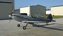
2. Builder Visit w/ Bud Tedesco (Kit #16) - On a recent trip to MCO for recurrent training, I was able to get up to Mount Dora, FL and visit Bud and see his aircraft. He's doing a fabulous job on it and is hoping to have it flying by the end of the year! Nearly all the systems have been installed and tested. He is currently working on installing all of the fairings and finishing up odds-n-ends. Here are a few pix of Bud's Beauty:
So far, Bud is the only builder that has incorporated a sliding canopy design into his Prowler. He came up with an ingenious design that allows it to work on a cockpit that is wider at the front than at the back. We'll look at incorporating this into our aircraft. BTW - that's Bud waving from the cockpit in the first picture above. Great job Bud - we'll keep tracking your progress. Hope you make your goal to have your aircraft fly this year.
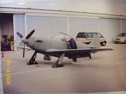
3. Redding Air Show - The promoters of the Redding Air Show called George this year and asked him if he would, again, display his Prowler at the air show. He agreed and we spent Thurs before the airshow getting Kit #005 out of storage, towing it up to KRDD, putting the wings on, and giving it a much needed bath. This was our first opportunity to see how the airplane is taken on and off of the trailer, how the wings are put on and taken off, and enjoy seeing folks enjoy the airplane. There is now doubt about it - this airplane gets lots and lots of looks!
We may have gotten even more looks if it hadn't been 112F on the field that Saturday! It was hot, but it was a great show. Of Course, these guys always get the most looks!
4. Bryan's (Kit #007) Progress - A bit of a slowdown at work has allowed Bryan to really get some work done on his Prowler. He recently sent me a video of his flap operating system in operation. He chose an updated version of the electric linear actuator that George and others have used to operate the flaps. This design has a ball-screw drive with automatic clutching at each end. This negates the need for limit switches, provided that you get the correct stroke length. It does, however, require that a different mounting system be created to attach the fwd end of the actuator to the bulkhead. Here's a video:
http://www.blogger.com/video-play.mp4?contentId=76805bafaeb2cb07&type=video%2Fmp4
NOTE: Bryan also requested us to ask if there are any current builders out there that need the high tensile wing bolts - please contact us. He is going to order some of them and will order enough for everyone. These are sold only in lots of 10 (w/ certification paperwork). He will order enough to get everyone what they need and divide them up when received. Email us for details.
5. Work on Tailwheel Struts - We've ordered the stock material for the tailwheel struts and identified a machine shop to begin making these from our newly made drawings (see previous post). This is to support the current builders that are in need of these items. While we're at it, we'll make a couple extra struts - one for our aircraft and one for possible future needs. Here's an updated 3D version of the TW strut since we "tweaked" the design a little. We should have some new pix for the next update.
6. First Attempt At Bend Radius Jig - We made a first try at making a bending radius jig to make bending 2024-T3 in the box brake easier and faster to do. Since we have a lot of this type of forming to do now (and even more in the future) we are putting time into making these processes very quick and efficient so production can be as efficient as possible. So, we tried welding a 1/4" round stock to the edge of a 1/4" piece of flat bar to create a "jig" to lay on top of the material to bend in the brake. Unfortunately, the heat from the welding stitches caused the jig to warp and made it unusable. In addition, we found out the the top fingers on the brake cannot be adjusted back far enough to accommodate this design. So, we're on to "Plan B" and should have some more info and pix in the next update. If at first you don't succeed - try, try again.
7. Installed DRO on Bridgeport Mill Quill -
This project turned out much more successfully than the one mentioned above. For less than $40 (including shipping) we purchased one of these quill DRO's. It did not, however, come with the mounting hardware - so a little imagination and fabrication were in order. Here's what we came up with.We have one more idea to make this more practical and useful. More to follow.
8. Installed 3 Jaw Chuck on Lathe - Last year we purchased a older used lathe and restored it back to a usable condition. It came with a 4 inch 4 jaw chuck, but we need the convenience of a 3 jaw chuck so we purchased one from ENCO. Trouble was, this lathe is so old that no one makes a back plate for mounting the chuck (uses a 1-1/4" 12tpi fastener to thread onto the lathe spindle). So, we had to make one. First step is to weld a 1-1/4" 12 tpi nut to a piece of 1/2" plate that has a 1" hole cut through it.Next, put it on the lathe to true up the face and side. Also, cut a shoulder on the edge to give a raised area which will fit into a recess on the back of the chuck (ensures it is concentric when installed on back of chuck). Drill 3 holes to bolt the back plate onto the chuck: Install the back plate onto the chuck: Install the completed chuck and back plate onto the lathe.
The dial indicators says run-out is less than 0.003" from side to side (less than 0.0015" from center to OD of the chuck). Good to go! Eventually we'll get a bigger and better lathe and this will be converted and set up to make one or two specific parts. But for now, we can use it to make several of the aircraft parts as well as general shop work.
9. Purchased a MIG Welder-
To facilitate making many of the jigs, tooling and other items needed to produce Prowler parts we needed to purchase a MIG welder. After months of watching the local classified and craigslist we found the right package at a great price.It's already been put to good use and it welds great. Of course, all the weldments for the aircraft parts will all be TIG welded (which we will outsource to a qualified welder initally). However, eventually we hope to purchase a TIG welder and take welding courses to bring this part of production in house as well.
Those are the high points for this installment. Next post we'll have a more complete update on the status of all the builders and their aircraft. Thanks for checking in on us and look for a Halloween update.
Saturday, August 29, 2009
A FEW MORE STEPS
A FEW MORE STEPS
Just a quick post to update the latest Prowler progress:
1. Catch up on the Vert Stab.
2. Horiz Stab Work
3. Computer Modeling Parts
4. Builder Update
1. Catch up on the Vert Stab. – In the previous post I mentioned that Dave has been working on assembling the Vert Stab Subkit. Here are a few pix of his handi-work.
Now they have to be heat treated, since they are formed from 2024-O (soft) material. Here are the horiz stab spar parts and cover plates cut out and waiting to be bent up in the sheetmetal brake. I used a buddy's sheet metal shear and it made cutting these out very easy.
Other horiz stab parts:
3. Computer Modeling Parts - Well, we have begun in earnest to model all the parts that make up a Prowler. This will be needed to setup the CNC plasma torch system to cut the flat parts. We purchased copies of BobCAD-CAM and are in the learning to use it process (steep curve right now). It's actually a very powerful program for the price and fairly intuitive - once you watch several of the video tutorials. Here are some examples: The vert stab aft spar;
Main Landing Gear Pivot Link:
Tailwheel Strut:
Just a quick post to update the latest Prowler progress:
1. Catch up on the Vert Stab.
2. Horiz Stab Work
3. Computer Modeling Parts
4. Builder Update
1. Catch up on the Vert Stab. – In the previous post I mentioned that Dave has been working on assembling the Vert Stab Subkit. Here are a few pix of his handi-work.
2. Horiz Stab Work - Dave's been itching to get to more assembling and I wanted to do something besides work on the plasma setup, so I decided to get some creative work going for a change and started fabricating the parts for the horiz stab subkit. These 8 parts were about 9 hours of work:
Now they have to be heat treated, since they are formed from 2024-O (soft) material. Here are the horiz stab spar parts and cover plates cut out and waiting to be bent up in the sheetmetal brake. I used a buddy's sheet metal shear and it made cutting these out very easy.
Other horiz stab parts:
3. Computer Modeling Parts - Well, we have begun in earnest to model all the parts that make up a Prowler. This will be needed to setup the CNC plasma torch system to cut the flat parts. We purchased copies of BobCAD-CAM and are in the learning to use it process (steep curve right now). It's actually a very powerful program for the price and fairly intuitive - once you watch several of the video tutorials. Here are some examples: The vert stab aft spar;
Main Landing Gear Pivot Link:
Tailwheel Strut:
Close up of the 3D view of the strut - BobCAD-CAM ver 23 does well with the 3D:
Now, only 687 more parts to go (just guessing)!
4. Builder Update - Ray Siem reports that Chuck has his airplane and engine back together and the engine is running well. His problems apparently stemmed from a damaged, or lack of, the mechanical stop in one of the distributors. On one of them the cap had a hole in it where it looks like part of the centrifugal stop system exited the scene and it let the engine vacuum advance run way to advanced. He reports that the engine is running well with coolant temps in range and no noticable issues. He is going to continue to test run the engine while he is going also going thru some medical issues. No date for the next test flight, but we'll keep ya posted.
That's it for this post. It's late and crew services could call in 4 hrs. Thanks for checking in.
Subscribe to:
Posts (Atom)