As the title of this post implies, I've got a lot of projects that are started, but most are lacking any level of completion yet. The list of current projects (and items covered in this update) are:
1. Finish assembling the entire main wing spar.
2. Finish building the wing jig (that has been hanging fire for 5 years!).
3. Finish building the "Prowler Rib Smasher." The two problems holding up this project are:
3a. Rebuilding the 100 hydraulic ram
3b. Finding a "high speed" pump solution to work with the "high pressure" pump.
4. Building an organized tooling cart for all the mill and lathe tooling.
5. CNC project for a friend.
6. Fixing the "Why won't it go, Daddy" on the Razor MX500 motorbike rear wheel.
One completed project for this update:
7. I now have a DRO (Digital Read Out) on the Bridgeport mill (again).
Before I get started on the update, I really want to thank my father for all of his help and support over the years. He as spent many hours helping me brainstorm, troubleshoot, build and/or fix a lot of the Prowler tools and machines that I will be using in production (hopefully) some day. Also, while serving my apprenticeship (growing up fixing, building and working on all manner of things around the house and shop) I learned so much about how to accomplish a lot of these projects. Were it not for this experience, I would never have gained the knowledge, insight or confidence to tackle a project of this magnitude. So, thanks Dad. I appreciate your help.
1. Finish assembling the entire main wing spar - I've finally cleared off enough space on one set of tables (from all the parts of all the other projects that are hanging fire) to begin doing the temporary assembly of the wing spars. These parts are long and take up a lot of table space in one direction. Here's a shot of the center section laid out with the RH outboard section.


These wing attach plates are the most important part of bolting the outboard wing spars onto the center section. They are also integral in holding the MLG torque tube spherical bearings in place and help to align and hold the MLG torque boxes in place. You can see how they are used in this pic from Ray's numerous photos:
.JPG)
When I do have these plates finished, I will continue the process of figuring out how I will get the proper alignment and hold everything in place while I ream all the holes to the proper sizes for the temporary assembly. Once the temporary assembly of the entire wing spar is complete, then I will be working on getting the wing jig completed (which is covered in the next Item below). When I've completed building the wing jig, then the wing spar must be completely disassembled into parts and every part will have to be acid etched and then chromated (Alodined) before final assembly. Then the entire assembly will go back into the jig.
2. Finish building the wing jig (that has been hanging fire for 5 years!) - So, as you can see from the picture below, my dad helped me build the first phase of the wing jig way back in Mar 2007!


What needs to be done on the jig, once it is cleaned out and ready for the spar, is to complete the location of the 4 center posts. The two posts that you see in the picture are for mounting the ends of the outboard spars (actually attaching the tip ribs). The location of these two posts is very well defined (by wing span). The 4 center posts have a little variability. Two of these 4 inner posts attach to the underside of the main spar (fwd side) just inboard of the MLG torque boxes and on the under side (fwd side) of the wing spar attach plates (see how all this stuff is related).
The other two posts attach to the underside of the spar (fwd side) inside of the MLG wells and attached directly to a spacer plate that is placed between the spar cap strips on the fwd side of the spar. The inner posts must be made removable so that you can remove one side at a time when the time comes to install/cycle the MLG.
Needless to say, all these posts have to be accurately placed, and be precisely the correct height so that the spar is completely flat and level when it is finally installed. Fortunately, George had a pretty detailed and complete drawings to help build the jig and I have compiled a good set of reference pix from George and the previous builders..
3. Finish building the "Prowler Rib Smasher" - The day after I get the spar finally assembled and installed in the jig, my focus will shift to "decorating" the spar. By "decorating" I mean installing all of the "stuff" that gets attached to the spar. The most numerous of these parts are all the wing ribs. Obviously, before installing the ribs, I have to fabricate them and that is where the PRS (Prowler Rib Smasher) comes into play.
I've addressed this topic many times in previous posts, but now I have the mechanical side of this forming press completed (with the help of my father). My dad is a retired Ironworker and spends the winters "snowbirding" in Phoenix. When spring comes, my folks drive out for a family visit before heading back to Wisconsin. Having spent a winter without any welding, cutting torches, grinding etc., dad enjoys (I hope) having a project to work on with me in the shop. This year it was the PRS, which is a 100 ton press that is (now) fitted with special box that will contain dies, blanks, and rubber while "squishing" the ribs into shape.
The first step was to evaluate all of the existing parts that could be used and then determine what steel needed to be obtained to form the lower "box" and the upper "lid." We also had to figure out how each of these was going to be attached to the frame of the press. Here is a pic of the fabrication of the remodeled lower platen with "Pops" in the background:


3a. Rebuilding the 100 Ram
After testing and finding that the pressure would not hold, we investigated the cause. We determined that the ram's piston seal had to be leaking. This started a 3-day project of re-boring and honing the ram cylinder and re-sealing the piston and ram cylinder.
The first step in the process was to make a spanner wrench to remove the ram packing retaining nut:


Dad and I were somewhat surprised to find that these seals are still made of leather. Turns out that despite more than 100 years of technological advances, leather is still the best material around for making seals in demanding applications. There just isn't a better material that will form to irregularities on the sealing surfaces, remain pliable at extremely high and low temperatures, withstand abrasives, etc. etc. Pretty amazing.
I just picked the new seals up Fri pm and won't be back in the shop until late on Sun. I should have the 100 ton ram put back together on Monday. It will be very nice to have this project off my plate (and off my work bench)!
3b. Finding a "high speed" hydraulic pump solution - When we tested the PRS, we discovered that the cycle speed of the ram is very slow (I expected it to be slower than when I was using it in the press brake - but not THAT slow). So, now I have to find a way to quickly close the press (raise the 100 ton ram) until it begins to compress the rubber by some amount. Then (I think) I'll have an isolation valve to isolate this "low pressure, high speed pump" from the system. Once isolated, the high pressure, low speed air-over unit would compress the box fully to form the ribs.
Reversing the process would be relieving the system pressure to the point that the valve was closed on the way up, then opening the valve and relieving the pressure the rest of the way into the high speed pump. This process will have to be monitored to ensure that one or the other of the pump reservoirs doesn't overfill with hydraulic fluid.
Another option is to install a larger bore manual pump (like the one removed from the bottle jack) to help move a lot of fluid fast, then switch to the air-over unit. I'm not sure which way to go yet. But, I've got a little time to figure it out before I really have to start squishing wing ribs. More to follow on this project.
4. Building an organized tooling cart - As I get involved in more machining projects for the airplane, the amount of tooling that I've got laying around is getting a little unmanageable. I've got some stashed here, some there, etc. Well, a few months ago a buddy gave me two large drawer units that work excellent for storing all of the tooling, measuring, and setup equipment that is used with the mills and lathes. Also, I have to find a place to store all of the metal bits and pieces that I have to clean out of the wing jig.
One day I had a revelation and decided that if I can find a nice, organized place to keep all of my machine tooling, then I can used the mish-mash of current shelves as space to store all the metal. The only problem was building (and finding a place to put) the machine tooling cart. I think I've found a little real estate in the shop for the tooling cart. So work began (feverishly) on building the cart. I scoured my junk piles and found steel, steel shelves, casters, etc. that would go together without too much effort. Then I hauled out the drawer units and started to clean, scrape, bang, bend, sand and paint the drawer units back into decent shape (they'd been a little abused in the past). Here is the current state of the project. Here is one drawer shell setting on part of the newly fab'ed cart:


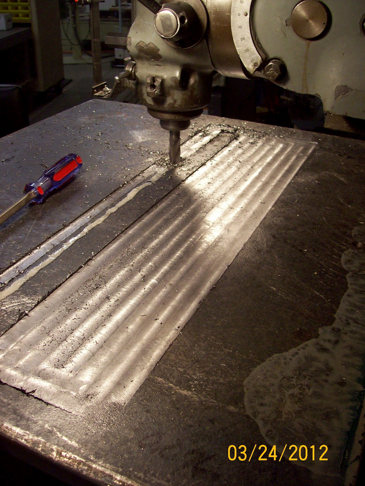
5. CNC Side project - I have a friend that needed some help getting a CNC project underway. He asked me if I would give him a hand getting some programming and parts done. I was kinda looking for a project to help me learn to use my Ganesh CNC mill. So, we agreed on some terms and I set out to get it done.
So far, I've gotten the majority of the fixture plate (and sub-base) fabricated. This fixture plate will hold an entire set of the parts that he sells online for a product that he makes. Here is a pic:

In order to get some product out the door, I used my CNC mill and wrote the needed code to finish a set of his parts. He had gotten behind on several orders and really needed to get some product out the door so I completed the 1st 15 sets of parts a few weeks ago. Here are some examples of the parts to be made:

6. Fixing the "Why won't it go, Daddy"- On a recent arrival home after the "day job" I was informed that the small electric motorbike that the girls have wasn't working. After a fairly quick investigation it became apparent that the clutching mechanism that allows the rear wheel wheel to "free-wheel" when the electric motor is not on and working was worn beyond repair.

Here you can see one of the little dogs that the wheel can free-wheel over in one direction, but then "takes a bite" if turned in the other direction. The dogs were all chipped and worn as well as the teeth in the other part. The spring that holds the dogs was also mangled. Best just to replace it all.

Now, for the ONE project that I HAVE finished!
7. Bridgeport Mill DRO - I recently got a good deal on a new DRO for the mill. It's an Anilam Wizard 411 made by Acu-rite. The instructions were easy to follow and it basically took one full day to install the readout and the scales onto the mill. Here's a pic of the Y axis scale installed:


That's all for this update. Hopefully, I will get another update done in a few weeks showing some closure on a lot of these projects. Until then, have a great spring season and thanks for stopping by to see the progress (or sometimes the lack of progress) here at the new Prowler Aviation.


1 comment:
There are many tools in aviation industry that works on the principle of hydraulics.The maintenance of the hydraulic parts is very important as they also plays a major role in operation of aircraft.
Thanks
Henry Jordan
Hydraulic Cylinder Seals
Post a Comment