Howdy!
Thanks for stopping back to check in on the New Prowler Aviation.
The past several weeks have been pretty productive around here. I am finally bringing together many facets of the (seemingly endless) work that I've had to do to lay the ground work to put together some production capability for making Prowler airplane parts.
Well, finally, a few days ago (all in one day) I:
1. Tweaked the CAD drawing for the tip rib;
2. CAMed out the tool path for it;
3. Fired up the Motionmaster router and loaded the program;
4. Put the 2024-T3 Aluminum in the router;
5. Cut out 2 tip rib blanks;
6. Grabbed the two tip rib dies (made the week before);
7. Put a blank on each of the forming dies;
8. Put it them in the 100 ton press (one at a time);
9. Ran the pressure up in the press, and.........
10. Successfully made a set of tip ribs!!
Cue the "Happy Dance":
THIS IS A BIG DEAL !!!! - At least for me. Here's why.
Because, (as the title of this post implies) this small accomplishment represents the validation and culmination of over 5 years of work I have done to establish production processes for the Prowler parts that have to be "formed" (such as wing ribs, bulkhead formers, etc.).
In order to be able to accomplish this one seemingly small task, the list of items that I've had to do and the things I've had to work on includes (but is not limited to):
=> Researching and finding an affordable CAD software;
=> Learning how to use the CAD software;
=> Actually doing the CAD work for each and every part of a Prowler (individually, one-by-one for over 1200 parts);
=> Researching, studying and learning about CAD/CAM production processes;
=> Taking a wrong path with regard to using plasma to cut airplane parts (including buying, fixing, building, and learning to use a CNC plasma system);
=> Finding purchasing and transporting the Prowler Motionmaster CNC router;
=> Fixing, re-designing, re-wiring, remodeling, repairing, and installing the Motionmaster;
=> Locating manuals, studying and learning how to program and use the Fagor 8025M control on the Motiomaster;
=> Finding, transporting, fixing and installing the Ganesh CNC mill;
=> Locating manuals, studying and learning how to program and use the Fagor 8040 control on the CNC mill;
=> Researching, studying, learning how to do machining on various materials to make parts with a CNC mill (basically becoming a half-baked machinist - both manual and CNC);
=> Researching, studying and learning about hydroforming and rubber pad pressing techniques;
=> Re-designing, remodeling and repairing the 100 ton press to function as a pseudo-hydroforming press;
=> Researching, repairing and rebuilding the 100 ton ram in the 100 ton press;
=> Designing from scratch and installing a new hydraulic system for the 100 ton press;
All of that was done while:
=> Keeping a full-time airline job (sitting reserve);
=> Trying to help raise 3 kids;
=> Fixing and improving the house (& shop & property) that is still $100K underwater;
=> Supporting the current builders (as best as I can) when needed;
=> Keeping these blog updates as frequent and informative as I can, and;
=> This past year, helping to save 2 original Prowler kits from getting melted down into scrap metal (and then subsequently making 100's of parts to make these two kits more complete).
Oh, and trying to keep the debt down while funding all this out of my own personal income.
Yup, the happy dance is well deserved - if I do say so myself!
OK - enough patting myself on the back. Time to get back to work - there's still way too much to do.
IN THIS UPDATE:
1. New Rubber and Final Repairs to the 100 Ton Press;
2. Making the Tip Rib Dies;
3. Cutting the Tip Rib Flat Blanks and Forming the Ribs;
4. New MLG HCAB Welded and Painted;
5. Builder Updates:
5.A. Bryan's Latest;
5.B. Francis & Robert;
6. New Nose Ribs for Francis & Robert;
7. More Parts for Kit #006 and Kit #018;
8. EAA AirVenture 2014.
1. New Rubber and Final Repairs to the 100 Ton Press - After the 1st test of the press, I had a hunch that the rubber I was using wasn't hard enough. I did some research online and found out that the rubber I need has to be about 70-80 durometer. I hunted around for a block of rubber that fit the dimensions of my press box and was (ideally) 3 inches thick. Well, the only options I could find would break the bank.
Then, on the way home from work one week I decided to drive down into Sacramento to the Capital Rubber Company to see what they might have. They had some new 70 durometer rubber sheet but it was only 1" thick and 12" wide (I needed 14" wide). But, the fella that was helping me said he could cut me a couple of 2" strips that I could glue to the larger ones. The price was tolerable for 2 sets so I decided to give it a try. I figured I would start with 2 inches and see how it works. If I wanted to, I could add another 1" sheet later. So, here was the haul that I took back to the shop that day:
The sides of the cut strips were not too perpendicular to the sheet, so I ran them by the sanding disk a few passes and squared them up a little. Plus, I figured the rougher surface would help the glue to bond better.
Here are the two parts with the adhesive on each piece just before putting them together. This adhesive goes on each half and then dries til tacky. Once you touch them together they are bonded instantly - so you have to get the line-up correct:
Here is one set after bonding them together:
And, both sets stuffed into the press box.
I did not bond the two sheets together. I reasoned that with all the motion that goes on in there with 100 tons of force applied to them, the laminations are going to move around anyway and the action of multiple layers might give better results than one big solid piece. Time and trial will tell.
I also had a revelation about how I was using the press. During the 1st tests I was placing he die on the bottom of the box (right side up with the die on the bottom and the blank on top), stacking the rubber onto it, and then pressing the part. It requires loading and unloading the rubber every time I want to make a part. Then, I remembered a drawing I had seen of a rubber pad press that I ran across while researching all of this stuff.
The rubber pad "box" is on the top platen and moves down over the part/die. Well, who says I have to have my die and blank right side up? Why not just flip them over and push them DOWN into the rubber? So, that is what I am doing now and it seems to work just fine.
2. Making the Tip Rib Dies - The first step in the process of using a die to form a part is to cut the die. The die has to be thick enough to prevent the flanges from hitting the platen on the press when it is forming. Since I have 3/4" flanges on almost every part, 1" thick aluminum is a great material for making the dies out of. The only problem is availability and cost. I can find a lot of 1/4", 1/2" and 3/4" aluminum plate - but 1" thick material is not readily available (at least that I have been able to find, so far). I can find 1" material online, but the cost and shipping makes it almost prohibitive for me right now. So, I've had to resort to laminating layers of 1/4" & 3/4" or 2 layers of 1/2" to get the 1" that I need. Here is a piece of 1/2 plate that I found to make one of the tip rib dies from:
Next I had to cut it length-wise into two pieces:
Then stacked the two pieces and clamped them while I got a few holes drilled to bolt them together:
The 4 bolts you see here are just to hold the two pieces together while the stack is in the mill and I can cut the hole patterns in the die that will actually hold it together. These 4 bolts are actually outside of the die profile and end up getting cut off:
Here is already completed die that shows what the bolt pattern looks like that holds the whole die together:
Here is the stack in the mill getting the profile cut. I decided to try a slotting operation to cut out the profile by making several passes with a 5/16 end mill. It takes a lot of passes and a long time:
Almost 1/2 way thru. This is the die to form the LH tip rib:
A little more than 1/2 way thru:
And, finally, done with the profile operation:
Notice the gap under the die. That is there so that I can run these cutting operations without having the cutter actually cut into the fixture plate (steel). It just makes the cutters stay sharper a lot longer when they are only cutting aluminum and not having to cut steel:
With the profile cut, the next operation is to cut the round-over of the top profile corner. This is a 1/8" radius (14" diameter) round over. This is a crucial part of the die design that helps to prevent the tempered aluminum from being bent too tightly; which will cause it to crack and split instead of form smoothly over the die:
With the round-over operation done the next step is to undercut the die. This undercut is to allow the flanges to be "over-bent" during the forming (pressing) operation to allow for spring-back. Aircraft aluminum is so tensile that it will spring-back as much as 10-12 degrees after it is bent. This undercut of the die gives the flange room to "over-bend" so that when the pressure of the rubber is released the flanges will spring-back to approximately 90 degrees:
This undercut operation is done in 3 passes and ends up with the very top of the undercut operation just barely (but not quite) touching the bottom of the round-over pass. If you look closely you can just see the line between the two operations:
And, finally, the completed die:
Out of the mill and on the bench:
A closer look after cleaning it up a little with a rol-lok buffer disk:
Here is the completed die for the other tip rib (RH):
Here are both dies on the bench:
Finally, several years after doing the CAD drawings for these tip ribs, I finally used those drawings to make the programs to cut these dies. This was another "happy dance" moment.
3. Cutting the Tip Rib Flat Blanks and Forming the Ribs - When you are forming a flat blank around a curved surface, the outer edge of what will become the flange must be compressed, or shrunk. This drawing helps to "visualize" this:
To deal with this, there are a few options. First, you can use a draw press which holds the outer edge of the flange tightly and pushes the die into the blank material and literally stretches the material as it forms the part. Second, you can slot the flange (make tabs) to allow the material along the outer edge to form over the die and not fold or break. And, finally, an additional option would be to flute the flange. It might be possible to cut slight depressions into the edge of the die to allow the material to flow into these areas and eventually create flutes in the flange.
Before I started to make the tip rib dies, I asked several of the current builders for their thoughts on which method might be best. I got some great feedback and in the end, I decided to go with the tabbed method. It seemed the most straight-forward solution that I could accomplish with the equipment that I have and it seemed the most likely to be successful for me. Trust me, I need all the success I can garner.
Once I decided on using the tabbed approach, I had to worry about where the slots would be placed and had to ensure that I wouldn't have a slot where the builder would have to put a rivet. To deal with that, I first laid out the rivet patterns as they are depicted in the drawings from George's builders manual.
Then, I asked around again and got the spacing info I needed and planned how the ends of the rivet lines on the wing would intersect at the tip ribs. I put that into the following CAD drawing:
With that information, I was able to draw out the entire rivet spacing on the tip rib flanges, both forward and aft of the main spar. Then, I went in and placed the slots where they would be in-between the rivets. I then erased the individual rivet markers, and cleaned up the drawing to this:
All that was left to do was complete the CAD drawing and CAM it out for the Motionmaster router. Here is a pic of the router cutting the flat blanks that will eventually become a tip rib:
And, one tip rib blank cut out:
I cut the other flat blank and then placed them onto the respective dies. The blue tape on the far die is to hold the small tooling hole pins in place so that they don't fall out while I'm inserting the die/blank combo upside down into the press:
I put the first combo in the press and when it came out it was formed well around the middle of the tip rib, but the ends were not completely formed.
I'm not sure why this was happening, but the solution was to stack a little more inner tube rubber near each end of the die and less in the middle. After doing that and re-running the die/blank in the press for one more round of 100 tons - it came out looking like this:
Much better.
When I pressed the second rib, I just left the extra stack of rubber on each end and the part came out formed in one shot. Actually, the flanges are made fairly short (on purpose) near the leading edge. In those areas the flanges were still not bent completely tight to the die. So, in that area I had to take the rib and clamp it in the vise with one die on each side. Then, I was able to take a hammer and just lightly tap the flanges down to get them to fit nicely. Here are the ribs after doing this:
Finally, successfully forming a Prowler part from scratch!
Remember, the purpose of doing all of this is to have a part that is ready to go as soon as it is formed. I could use the old "tried and true" method of forming parts from 2024-O (Tzero) material and then have them heat treated. The result is basically the same, but it adds cost and logistics to the production process.
Plus, during the heat treating process, the parts can warp and distort. This has created headaches for the builders in the past. With this "pseudo-hydroforming" process these parts come out of the press straight, true and ready to ship.
The pressing operation didn't go off completely without a hitch. While I was running the press up in pressure a few times I heard a loud snap and an associated drop of about 2,000psi of hydraulic pressure. I wasn't sure what was causing it, until I was finished with the 1st rib. I looked down and noticed this:
I looked on the back side and, sure enough:
Rats!!! I was a bit concerned at first. Then, I deduced what had happened. When dad was in the shop this spring and helping me with the press, he had laid a bead of weld into the 4 joints where the bottom H frames join the upright C channels. When he welded these, the C channels were slid down and resting on the tops of the bolts that you see here that hold the H framed to the press. Later, with 100 tons of force trying to pull the C channels UP the welds broke and the C channels then caught (landed) on the bottoms of the bolts. Basically, there was "slop" in these holes and the welds were put on before the slop was taken out. So, when I pressed the second rib, I ran the press up about 1/2 way and then stopped. I then ground out the cracks in the welds and re-welded the joints.
No more problem!
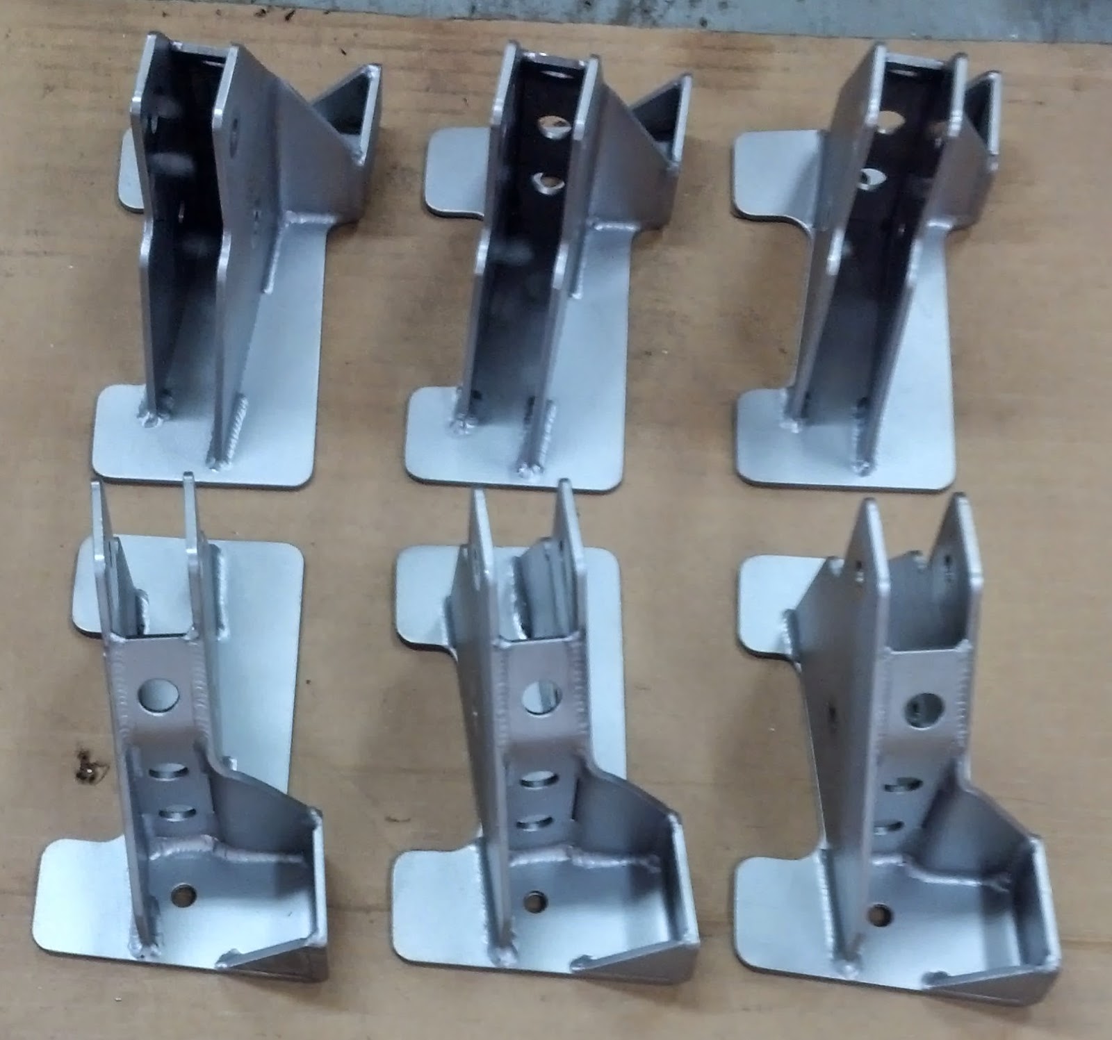
4. New MLG HCAB Welded and Painted - You may recall from a previous post that I have several builders or kits that needed a set of MLG Hydraulic Cylinder Attach Brackets. I posted then how I made the fixture and cut out the individual parts that make up these brackets. I had made 4 sets, but the very first set went to Francis (in France) and he welded the pieces together to fabricate his set:
I finally had time to get my 3 sets to the welder. Here they are after welding and before lightening holes and paint:
And:
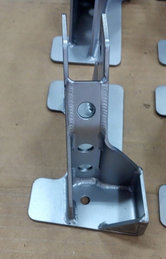
Recall, these were designed by Bryan to also incorporate the negative G mod in with the HCAB. This pic show the neg G mod flange with gussets on the upper right.:
My buddy did an outstanding job with the welding. Here's the back side with the gussets for the neg G mod again on the lower right:
The next step was to cut the 1-1/4" lightening holes in the large flanges to help save a little weight. The pilot drill on the hole saw goes right into the tooling holes (seen above) that I used to hold the parts in the fixture while cutting them in the mill. Here is one in the mill getting the hole cut:
One set goes to Bryan for Kit #006, one set goes to Kit #018 that I am making missing parts for, and the final set is for my airplane. Finally, some paint and they are all ready to go.
5. Builder Updates:
5.A. Bryan's Latest - Here is the latest update from Bryan:
I am finally making
measurable progress! At OSH I was able to resolve quite a few issues with
vendors and most importantly now have a production date of March 2015 for my engine. I will receive a foam
engine block before that to build the mount and cowling around. As a result I
have been methodically working down the punch list finalizing everything
firewall aft.
I installed the
electronic oxygen system,
added the last avionics to the instrument panel (
which still needs labels)
(My Note: And, they call this stuff "wireless" radio! Ha!)
(My note: Beautiful wiring job, Bryan!)
(My note: Awesome gear switch handle - he custom made that for his gear switch.)
and the pulled and re did all four flaps. The gap
between the flap in both the extended and stowed position, and through its
entire range of motion is now .020 or less.
(My note: On the Prowler the leading edge of the flaps are a basically the skin sticking out the front of the flap and then the skin is rolled around an appropriate sized piece of pipe to curl the edge to slip under the trailing edge of the wing. It's not the greatest design, but is does work. Bryan was not happy with the way his fit up to (and under) the trailing edge of the wing skin. He had been threatening for years to replace that "filler" flange with a piece of thin walled aluminum pipe. Since he has had a lot of time in the shop lately, he finally did just that. The result is impressive. It's a perfect curve, rigid and fits well up to the trailing edge of the wing. Really nice craftsmanship there, Bryan! Looks great!)
After operating the
landing gear about 50 times I noticed a leak in the right MLG cylinder so it is
now on the bench.
The next two weeks are scheduled for final canopy attachment.
I am attempting the RV-8 method of gluing it on with Sika Flex. I have read that
it is a smelly sticky messy process but produces superior results all
around.
Bryan Prowler #
007
At the time Bryan sent me this update text, he had not yet started the canopy work yet. He sent me the above pics of the windscreen a few days later. In that email he said:
Well, after all the Internet hype about this, and all the examples on the
Internet where builders were so afraid to do this.... (it) was nothing
more complicated than doing a very nice caulking job on your bathtub. If I have
time I'll do the canopy tomorrow.Looks very nice, Bryan! I'm sure that the canopy will turn out awesome. Thanks for the update.
Also, while at AirVenture, Bryan asked me about fabricating a frame to hold down his stick cover. A custom made frame similar to ones that go around stick shifters in manual transmission cars. I did the CAD drawing shortly after returning home:
Then, I sent him the above screen shot to confirm the design. He was happy with it, so the next opportunity I got I programmed the CNC mill to run the part. Since I was only making one, I just used a piece of thin press-board and clamps to hold the material in place (no fixture this time). Here is the mill running the program on the inside cut:
Here is the completed part after a little buffing with a Rol-loc disc:
Nice progress on your project Bryan. Happy to know that your leg troubles are starting to resolve and you can get around well enough to get some awesome work done on the plane!
5.B. Francis & Robert - Francis has been also making great progress on their Prowler project. They now have the entire main wing spar alodined and riveted together. Francis has started to fit the spar bridge pieces and the rib attachment angles. You can see them both here:
Here is the rib attachment angle at WS51 near the wing joint:
And again:
And the other wing:
This is a good overview of their progress:
And, from the other side:
Preparing to fit the nose ribs:
and the same here:
Here are two pictures of his completed rib attachment angles for the outbard wings:
Here is the nose rib at WS51 on the inboard spar:
And another shot:
This is a great photo of the center section nose ribs starting to get fitted:
Awesome job guys!! It's beginning to look like an airplane wing! Excellent progress on your Prowler. We look forward to seeing more. Thank you for sharing your Prowler building with us.
6. New Nose Ribs for Francis & Robert - When Francis and Robert got their Prowler kit some of the nose ribs on the outboard wings were damaged. In at least one case, there were two ribs the same (instead of a RH and a LH rib). So, in short, I need to make them 4 new nose ribs. I will use the same technique as I did for the tip ribs that I described above. Since, I can now press these parts with my "Rib Smasher" press. I got started on this by finding some material in the shop to cut the dies from. I have been collecting some 3/4" aluminum and some 1/4" aluminum in anticipation of having to make many of these dies. I found one piece of 3/4" that I could get all 4 dies made out of the same piece:
Here I am cutting the individual pieces out (roughly) with a band saw:
I did a similar routine with the 1/4" flat aluminum and here they are all stacked together on the bed of the mill (with the old wood dies from George on the left):
I have found that tracing the old wooden dies onto the aluminum with a fat Sharpie marker makes a good outline to follow with the band saw. Also, if I make the bandsaw cuts along the outside edge of the Sharpie marks, that leaves about 1/8" to 1/4" of material for the CNC mill to remove when doing the profile cuts on the dies. That is a good size cut for about a 5/8"or 3/4" end mill to remove in one pass.
Once I got to his stage, I decided to send an email to Francis with a picture of the ribs I plan to make for them - just to verify I was making the ones he really needs. Because these dies have to be cut special for RH or LH wing ribs, I just want to be sure the make the correct ones for them (the first time). I will eventually need to make them all, so it won't matter in the end - it's just that they are moving along so quickly that I want to get the correct ones made for them so that I don't hold them up at all waiting for the correct nose ribs. Right now, I am just waiting to hear back. More to follow.
7. More Parts For Kit #006 and Kit #108 - Both "extra" kits that Bryan and I have right now need to have the outer MLG door attach brackets made for the kit (and I also need one for my airplane). So, I looked into doing this work. It involves bending a 5/16" x .049"Wall tubing to make a U shaped part. The bend in the part is about a 1/2" radius and would be hard to do with 4130 tubing. Here is the part that I needed to make:
You can see in this picture the function this part serves to hold the outer MLG door:
I decided that I needed to make a mandrel that would allow me to put the tubing in place and then heat the tubing while I bend it around the mandrel. I did a quick CAD drawing to help visualize this mandrel and see if it would work. Here is what I came up with:
Once I started to make the mandrel, I decided that I should change the shape slightly and add a recessed pocket that the tubing would slide down into to help hold the tube in place while trying to heat and bend it. In the following picture, you can see the extra square "block" on the top side that the pocket will be cut into. Also, this pic shows using a ball endmill to cut the rounded slot for the tubing to follow around and lay into while forming the parts:
With the basic shape of the mandrel fabricated, I next added the 1/2" radius to the two corners. Then I had to figure out the fixturing for the part to hold it in the rotary table while I used the ball endmill to cut that rounded 5/16" slot around the 1/2" radius. Here is the set-up that worked:
The hole that you can see in the madrel just above the upper clamp is a 1/4" centering hole that I used to center the workpiece onto the center of rotation for the rotary table. That way, when the handle is cranked on the rotary table, the bottom of that rounded 5/16" slot will cut around the 1/2" radius. Here is the mandrel out of the mill and in the vise with a piece of tubing pushed into the pocket that I mentioned earlier.
The next thing that I rationalize was that I would have to have a clamp of some kind hold the tubing close to the bend that would help hold the tubing in place and prevent the one side of the radius from trying to "kick out" (for lack of a better term). Here is the solution that I came up with:
Next I welded a heavy piece of 3/8" flat bar to the back side of the mandrel that sticks out down below so that the whole contraption could be held firmly in a vise. Like this:
All that was left to do was put some heat on the metal and walk the tubing around the groove that was cut in the side of the mandrel. When I get to the second corner, I had to put the clamp you see on top back down over the tubing to help hold it durng the second heating/bending operation:
With the piece formed, I still had to cut a saddle into the straight part to provide a place to weld the short straight piece you see in the part drawing (1st picture above). I am doing that here in the milling machine with an end-cutting 5/16" endmill:
All that was left to do before welding was to tap the end holes to 1/4"x 28tpi to fit the tie rod ends into that will eventually get put on the ends of this part:
Here is a set of the parts ready to go to welding. At this point the short straight pieces are not tapped yet. I reasoned that it would be easier to tap these once they are welded to the U shaped parts. It will also test the holding power of the welds. If I can tap the holes and the small parts stays put, then it will probably hold the gear door on adequately!
These 3 sets of parts are getting welded up as I am writing this blog update. I'll post pics of the completed parts next time.
8. EAA AirVenture 2014 - As the saying goes: "All work and no play, makes (insert name) a dull boy!" So, time must be made to attend AirVenture. I managed to get the whole family there again for at least one day this year (I made it on Mon-Thurs). Here are a few pics of my all-time favorite airplane. If I could have just one of whatever airplane I wanted, this would be it! The design philosophy of the F-4U was to take the largest, most powerful production engine of the day and build the smallest, lightest airframe to it that could carry the MOST amount of armament (bombs, bullets, armor) off of an aircraft carrier. What more could you possibly want?!?!?


Here is the Supermarine Spitfire engine on display at the RFA area. This could be a possible Prowler powerplant - although fitting it into the Prowler engine compartment will not be easy. The big belt drive housing adds a lot of "stuff" to cover up in the very forward pointy end of the engine compartment on our aircraft. But, it could be done - if you are good with forming sheet metal:
Here is the "World's Busiest Airport Tower" for the 8-9 days at KOSH around AirVenture time, every year. In the foreground are two ATC controllers. If you've never been to AirVenture you'll have to figure out how I know that. If you have ever been to AirVenture - then you know how I know:
There's Bryan checking over a turbine Stewart S-51. The Stewart 51 is the airplane that is most responsible for my life long quest to build a V8 powered aluminum aircraft. It was sometime in my teenage years when Stewart debuted his airplane at OSH. Standing on the flight line watching his airplane do a demonstration was the spark that lit the fire that eventually brought me to Prowlers:
The Osprey in Boeing Plaza:
My family in front of a Warhawk:
Where else would you ever again see 3 beautifully restored P-38 Lightnings parked on the same ramp together? Marge, Ruff Stuff and Glacier Girl are on display on the Warbirds ramp:
This was a first for me (and a first time this airplane was at AirVenture). I've never before seen a B-57 (the Brits called it a Canberra). See more here:
http://en.wikipedia.org/wiki/Martin/General_Dynamics_RB-57F_Canberra
OK, so last year I had to bug-out early from AirVenture and missed the first night airshow (Wed nites & Sat nites). I must say, the night airshows (if you've never seen one) is worth the cost of admission by itself!!! It is really something to see at least one time. It's amazing to see the lighted smoke trailers, the streamers, and the fireworks (literally) popping off the sides of the aircraft. These pictures do not do justice to the sights you will see at the night airshow.
Check it out some year if you can. You won't be let down. You will especially dig the "Wall of Fire" finale!!
And, always remember: The WORST day at AirVenture still beats the BEST day of anywhere else you could be!
Well, that is all for this update. Thank you for stopping to check on the progress of the new Prowler Aviation.


%2Bat%2BWS136.png)


.JPG)
.JPG)
.JPG)
.JPG)
.JPG)
.JPG)
.JPG)
.JPG)
.JPG)
.JPG)
.JPG)


.jpg)


No comments:
Post a Comment