Merry Christmas Everyone!
Wow - another year has blasted past us! Since my last update was just last month, I only have a few items/projects to report for Prowler Aviation on this update. Here's the list for this update:
1. Prowler Motionmaster Fix
2. Several Steel assemblies for Kit 18
2.A. Neg G Stress Mount
2.B. Engine Stress Mounts
2.C. Tailwheel Upper Retract Yoke
2.D. Tailwheel Aft Retract Arm
2.E. Tailwheel Forward Shock Yoke
2.F. Instrument Panel Center Flange
3. New Prowler Engine Mount
4. Builder Updates:
4.A. Ray Solved The Gear Hydraulic Problem
4.B. Ernest Is Getting Closer to His Second 1st Flight
5. New Tool For Making Prowler Parts
6. Golf Cart Makeover
Since the last update, my knee blew up on me again just before Thanksgiving. In fact, I spent Wed - Sat of T-day holiday with my leg up and my knee on ice. No one is sure what happened, and a new MRI did not indicate any problems - so, now I'm back at PT after a mandatory two week "give your knee a rest" from the doc. If all goes well I'll be released to go back to work in mid Jan. In the meantime, I'm quite a lot more mobile now and I've been able to get out to the shop and get some parts made for Kit #18, among other things.
Thanks for checking in! On with the update:
1. Prowler Motionmaster Fix - You might recall, several years ago I purchased, refurb'ed, modified and installed an industrial CNC router in the shop that I found online. When I do finally make it into some kind of limited Prowler production, this machine will be running a lot! Here is what it currently looks like sitting in the shop:

So, about 6 weeks ago (after I got off crutches) one of my buddies who also has a CNC machine with a Fagor 8025 controller called to ask me if I had a spare backup battery module for the control. I did and that reminded me that I'd never changed the battery in my control. I went out to check it and it was 20+ years old - I was living on borrowed time. If this battery goes dead, you will lose all the parameter settings in the control and the next time you start it you'll see a bunch of Spanish come up on the control screen (default parameters). (If you have saved copies of your parameters, it's not too difficult to recover from this - but, if you don't have the parameters.....it will not be very much fun at all.) Well, I happened to be headed into town that day anyway and went to the battery store and got us each a new battery (AA sized 3.6 Li cell).
I got home and decided to fire up the machine and change the battery (you change batteries when the machine is running so that removing the battery doesn't affect the memory - it's being powered by the computer while running). I haven't run this machine for over 2 years. In fact, the last thing I cut with it was the blanks to make the nose ribs for Francis (OMG!!!...looking back in my pics, that was in Nov 2014....3 years ago!! Ugh!!) Anyway, after I changed the battery I decided to home the machine and then jog it around a bit. When I did - the X axis worked normally. But, when I went to home the Y axis, the table shot off at max feedrate for about 6 inches and then failed on a "following error." Well, that was not good. I reset the control and then tried to jog the table in the Y axis and it worked, but was not controllable after the initial push of the jog button. Each time, I had to hit the E-stop to get the machine to stop moving. Huh! That definitely was a problem.
A few days later, I got to troubleshooting the problem and eventually tracked the problem down to the Y axis servo motor. My machine has some crazy expensive Baldor servos on it (like $3.2K new, $1.7K used). All three axis servos are actually the same. They look like this:
There are really only a few things that can go wrong with a servo: 1.) the brushes wear out; 2.) the bearings go out or other mechanical failure; 3.) the motor windings burn out; 4.) the tachometer fails; or 5.) the encoder goes bad. My failure was not the motor windings (it was moving) and it seemed to be related to the servo's feedback to the CNC control (so it was an electrical problem). So, I could rule out problems 1, 2, & 3. That left 4 & 5 as the possible culprits. I yarded the servo out of the machine and got it on the bench.
I pulled the end cap off the servo that is opposite the shaft end to expose the encoder. I decided to start with that, since it was the easiest to get to (rotary encoders are mounted on the end of the armature shaft that is opposite of the output shaft) and because the problem seemed to be related to the servo feedback to the CNC (which is what the encoder is part of). I pulled the encoder off the servo and cut the cable between the cannon plug and the encoder. Here's what mine looked like under the end cap:
All that an encoder really is, is a pulse generator that has a marker in it that sends a reference pulse at the same position every shaft rotation - then sends out a stream of square wave pulses for each number of degrees of rotation. The number of degrees depends on how the machine is designed and the required pulse count of the encoder. They can be made with almost any number of pulse counts per revolution.
The encoder on this servo happened to be a 400 CPR (counts per rev). But, for demonstration sake, lets use a clock face as an analogy and pretend that we have a 60 CPR encoder. You can then think of an encoder sending a reference pulse (marker pulse) at the 12 o'clock position on each rotation. And then additionally, the encoder will send another square wave pulse at each minute mark all the way around the clock face. In this way, the CNC (computer) counts the pulse stream coming from the axis servo and can interpret from this where the machine is at - all the time. Here is my (failed) 400 CPR encoder:
I got online and figured out that by applying +5Vdc power to the encoder and using a DC voltmeter, you can do some rudimentary troubleshooting of an encoder. Of course, you have to know the pin-out of the device and hook everything up correctly. I found this and it helped me with the wiring info:
I discovered that the B/B* and Z/Z* channels were giving an output signal, but the A/A* channel was not. The A channel was stuck at +5 Vdc and the A* channel was stuck at 0 Vdc. So, this encoder was apparently shot. I used the page of info below that I found online for my encoder and called the company to order a new one.
Mine was not exactly a very standard pulse count encoder and they were going to have to build me one - so it would take a few weeks to get it.
In the meantime, I noticed when I took the servo out of the machine, that the shaft seemed to be pretty sloppy in the end of the servo and set out to also fix that. I pulled that end of the servo apart and I found that the bearing was loose on the shaft and the shaft had been spinning inside the bearing. It had worn the shaft down in the area of the bearing ID and it was now about .015" smaller in diameter where the bearing is supposed to sit. Well, this is also not good. Here is the old bearing:
This is a close up picture of the armature. You can definitely see that the shaft is worn down in the area where the bearing is supposed to seat:
My 1st thought to fix this was to have my master welder build this area up with weld and then turn it back down to the proper diameter in a lathe. But, the other end of the shaft is still connected to the section of the servo that has the brushes and tachometer in it. I really didn't want to take all that off, if I didn't really need to. You can see it here:

Huh!?!? What to do? Well, when I'm stumped, I go to the ultimate resource - Dad! I filled him in on what I had and he told me to prick the shaft. What!?!? Well, the idea is to put the shaft on a good stable surface and then use a sharpened prick punch to put small, symmetrical divots around the shaft in the "low" area where the bearing ID is supposed to sit. You basically deform the metal causing craters and sending some of the material out to and slightly beyond the desired diameter. This will give the ID of the inner bearing race something to contact and, if done properly, will keep the bearing re-centered on the shaft. Then, you position the shaft and put Loctite Bearing Set down into gaps and let it setup.
So, that's what I did with this servo armature shaft. I found a good piece of steel just the right height and cut a saddle in it with the same diameter as the armature shaft. Then, I positioned it on the welding table and punched the divots into the shaft. When I got done it looked like this:
I ordered a new bearing for the shaft and a few days later it showed up. I pressed the new bearing into place over the divots in the shaft:
Then, I stood the servo on end and soaked the area with Loctite bearing set overnite so that it would seep down into the gaps between the shaft and the bearing ID:
The next day, I put the servo back together (minus the encoder) and tested the new armature bearing. It rolled over smoothly and didn't make any noise. So far, so good. The next week, the new encoder showed up. Here is what $326 of new rotary encoder looks like (sorry, the pic is not in focus):
You might notice that I ordered the new encoder with 800 pulses per rev. While doing all of this troubleshooting, I discovered that the machine was originally built with 0.0005" resolution on the X axis, but only 0.001" resolution on the Y axis. Not sure why that was done, but by ordering an encoder with 800 CPR and changing one parameter in the CNC, I was able to make both X & Y axis have 0.0005" table resolution.
In the end, it took about an hour to solder in the new encoder, put the servo back together and install it in the router. I fired up the machine, changed the necessary parameters and gave it a test. All is well and machine is working fine again. I'm not sure what made this encoder go bad. It worked 3 years ago and then I turned it on last month and it was no-worky. But, I'm happy that I was able to repair it for a reasonable cost (approx $360) .vs. having to purchase a replacement (prices mentioned earlier)!! Time to put this machine back to work.
2. Several Steel assemblies for Kit 18 - I am getting down to very last parts/assemblies that I need to complete
Kit #18 that I have up in the office (yup - it's still for sale). I'm trying to get this kit ready for next summer. If Ernest does take his Prowler to Airventure, I am expecting lots of inquiries about the Prowler and I'd like to have this kit ready to sell in case someone really wants a kit to build. So, here are the parts I made for the kit recently:
2.A. Neg G Stress Mount - This is the part that attaches to the bottom of the bulkhead former in the cockpit area just over the wing spar. These attach to the former with several rivets and transfer any negative G loads to the main spar via a bolt that goes down from this stress mount thru the cockpit floor and into another clip attached to the top cap of the main spar. Here are all the parts (3 sets) laid out on a sheet of .050" steel:
Once the main plates are cut out, there are two tooling holes drilled into them and then they get mounted in the CNC mill, like this:
Here are the same parts after the profile milling of the edges and drilling rivet holes for attaching to the fuselage former:
And, here are the 3 sets of parts ready for welding:
2.B. Engine Stress Mounts -These are the steel pieces that mount into forward ends of the main fuselage longerons. The engine mount bolts go through these assemblies and transfer all of the engine flight loads into the fuselage. Needless to say, they are pretty important assemblies. They are made from 3 pieces of flat steel. The main body is cut from flat steel and is formed into a U shape. Then, there is another U shaped piece that fits inside the main body and gets welded to the flanges. Finally, there is a flat piece of thick steel that gets welded bottom of the smaller U shaped part to reinforce the area where the engine bolt passes through. Here is a sample assembly (left over inventory) and a sheet of steel cut to make the main body:

I don't have a sheet metal brake large enough to bend a piece of steel this thick and this long. And, besides, bending a part like this in sheet metal brake is prone to error. If you don't get your bend lines perfectly parallel, the part will come out wracked and not be useable. I needed to find a more accurate way to make this piece of the assembly. I decided to make a bending fixture (tool) for it. Here was my idea of how to form these parts from 4 pieces of steel that I had laying in the steel pile:
Next, I had to find a good, large piece of steel to use as a base to mount the other pieces to. Then, I had to position the lower dies and space them with shims the same thickness as the material to be fomed....plus a few sheets of paper for a small relief - and clamp it all together:
That got welded up. Then, I turned my attention to the punch die. Here it is upside down in the vise (after welding) so that I can file a radius onto the lower edges. You don't want these to be too sharp as it will deform the metal too much. It also doesn't have to be too big of a radius. I made it about 1/16" radius and checked it with a radius gauge frequently:
I could have put this in the mill and used a roundover bit to shape the
radius - but, it doesn't take too long with a good sharp file to do the
same thing by hand. Plus, it's good to practice this kind of work by
hand every once-in-a-while - to keep your handworking skills up.
Here is the forming tool all put together. I had to add some guides in the ends to keep the punch die properly aligned with the blanks and also to keep the punch die from going too far toward one end or the other.
Here it is in the 20 ton press forming the first part. Turns out, the punch die tended to roll one way or the other. I suspected that I did not have enough "bearing" area where the press contacted the punch die. More "flat" area up there would keep the punch die aligned vertically (the large round steel piece is just a spacer):
After a little wrangling, it did work for the 1st part and formed it adequately:
After forming that 1st piece, I stopped to weld a piece of 1/2" steel to the top of the punch die (nice and square to the vertical bar). Here is the tool pressing the 2nd part:
That final mod worked great and kept the punch die from wanting to roll over like it was previously. I went on to use it to form all 8 parts (I decided to make 2 sets of 4 of these assemblies):
Now, to make the smaller U shaped part that goes in the end of the main body and gets welded to the flanges. This part is thicker steel and definitely needs a bending tool. For this part, I did get a bending tool from George that he had made. Here it is, ready to form the first part:
Here it is in action:
When the part comes out of the forming tool, it is still not completely formed. There is still too much curvature to the bottom of the U. You can see it here:
I found that by pressing the parts again without the use of the bending tool makes the bottom of the U much flatter, but that also causes the flanges to spread back open. To fold the flanges back into a 90 deg bend, I found that a few whacks with 3 lbs hammer (via a piece of flat steel to take the hammer blow deformation) worked great. This made the pieces have nice square bends and formed them to fit nicely into the main body pieces:
Here is how these first two pieces fit together:
I completed making all the U shaped parts and then cut 8 pieces of flat steel and put a good radius on the edges of one side. Here are all the parts ready for welding:
2.C. Tailwheel Upper Retract Yoke - This assembly mounts between the mid-point of the tailwheel strut and the lower side of the upper aft tailwheel compartment. It guides the strut through the tailwheel extension and retraction cycles. This is what it looks like when finished:
The tough part of making this assembly is cutting the two long tubes that make up each side of the V shape. On the right hand side, the tube is essentially cut with taper that fits to the outside of the U shaped lower yoke. Cutting the tube to length is the first step. Then, I put it in the mill using a 5C collet and holder in the vise. Then, run an end mill of the same diameter as the tube to notch the upper end.
Then, after marking it in the welding jig, I took them to the band saw and used a clamp to help me make sure that I kept the tube from rolling while I was cutting it (keep it vertically aligned to the saw blade):
Then, I put all the parts in the welding jig and clamped them into position. This jig makes sure that the lower bushings are in perfect alignment and parallel to the top pivot bar (on the right in the picture below):
After this portion of the welding is done, the assembly gets transferred to a different welding jig that holds and aligns the side plates that you see on the finished part in the first picture above. That's all there is to that assembly.
2,D. Tailwheel Aft Retract Arm - This is the assembly that the TW hydraulic actuator gets attached to on the "live" end. The finished part looks like this:
I started this part my making the side straps. There is one strap of steel that runs along each side and has a flattened "Z" bend. Here are the pieces before bending (sample from inventory is on the right):
Here is the 1st bend in the sheet metal brake, using the protractor to check the angle (make them parallel):
There are several more pieces to make this assembly, but they are all simply cutting out parts from flat steel and drilling some holes. When the parts are all stacked up in the welding jig....it looks like this:
I also made 2 sets of parts for this assembly. Once you have everything set up to make one part, it only takes a little time and a little more material to make another one. Here are my 2 sets of parts ready for welding:
2.E. Tailwheel Forward Shock Yoke -This is the assembly that mounts between the top attachment point of the tailwheel strut and the forward bulkhead of the TW compartment. When finished the whole assembly looks like this:
The blue part slides in/out of the green part. The green part pivots on the gray posts. This assembly helps guide the top of the TW strut through the extension and retraction cycles. The idea of the the "shock" mount is that rubber is stuffed into the square tube. The blue part compresses against the rubber when a force pushes aft on the bottom of the TW strut (which pushes forward on the top of the TW strut) - thereby adsorbing the "shock".
Here is one set of the parts cut out and ready for welding. Most of the parts of this assembly are simply cutting off pieces of tubing or flat parts and drilling holes. There are 2 parts that need to be formed in some way. The first formed parts are the 45 degree flanges that go between the square tubing and the round tubing in the pic below. These flanges are cut from flat 0.050" steel sheet and then formed in a sheet metal brake. Here are all the parts that make up the forward half of this assembly:
Here is the solid square bar piece getting the holes drilled that will become a slotted hole in the "shock mount":
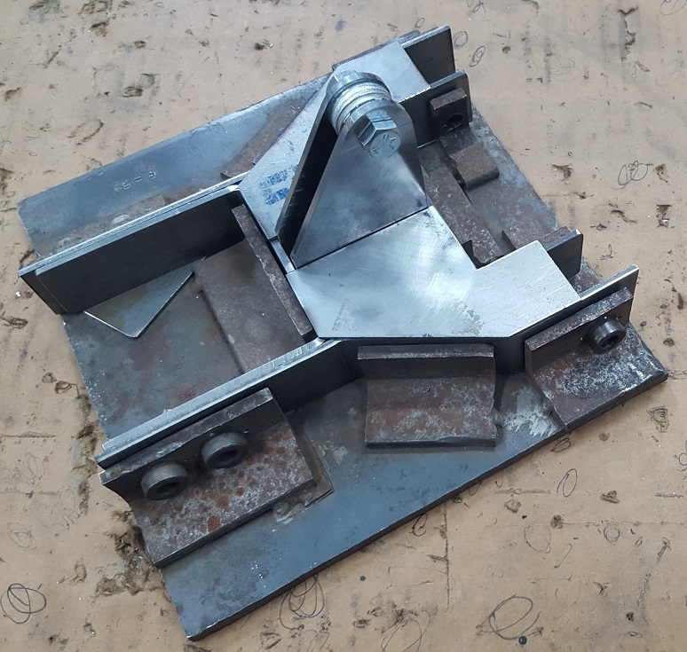
This is the other formed part in this assembly. It is made from pretty thick steel and required me to make a new tool for forming it (and other airplane parts like this). [See para. 5 below for the making of the new purpose built forming tool for this.] Here is the formed yoke part:
Here are the two parts from above clamped together and ready to be welded:
And, finally, here are all the parts of this assembly placed in their approximate positions and ready to be welded:
2.F. Instrument Panel Center Flange - This part is not fabricated from steel, but I still needed a set for the kit. It turned out to be a bit challenging to make. It is essentially a curved angle piece that is used to secure the top edge of the instrument panel to the upper skin of the fuselage under the windscreen. Cutting the strip of aluminum and bending it into a 90 deg angle is pretty easy - the trouble comes when you try shrinking the 3/4" flange to make the thing curve to match the radius of the top of the instrument panel. And, that is not a constant radius - it changes as you move along the edge from the top down towards the sides.
Let's just say that making this set of parts really expanded my metal working skills - at the cost of fairly elevated levels of blood pressure and frustration (for a while). Turns out, there is a method to the madness - you just have to figure it out (or be shown how). I ended up figuring it out on my own - but it wasn't until AFTER I broke one part and had to start it all over again. Here is the left side part laying above the radius guide/template:

The part on top is the part that I broke when trying to stretch it out (a little) in an area that had been shrunk quite a bit. Note: when you do a significant amount of shrinking to a piece of tempered aluminum in one area - don't go back and try to stretch it again! I won't stretch much, if any, before it just snaps. So, the real challenge is to continually take small amount of shrinking and compare it to the template and NOT over shrink it in the first place! Armed with that knowledge, I went on to finish the left side and even did a better job at making the right side angle flange. Here they both are placed on top of the radius template:
In the future, I am going to think of a way to form these with the 400 ton press and try to forego all this shrinking work.
3. New Prowler Engine Mount - I have been working with Stuart and Larry at AutoPSRU's for a couple of years now, preparing to have them create a FWF product for the Prowler. My plan is to sell Prowler airframes and then leave the Prowler builders with 2 options for an engine package. Option 1 will be to purchase the Prowler FWF package from AutoPSRU's; and option 2 will be to develop his/her own FWF solution (like what Bryan is doing with the Deltahawk diesel engine). I got an email recently from Larry at AutoPSRU's and he's gotten started on fabricating the 1st new Prowler motor mount. Here it is:
It's going to be a P-51 style engine mount and will hold the AutoPSRU FWF package to the existing firewall mounting holes on the Prowler. In fact, that's a Prowler firewall in the picture above. Larry made if from drawings and tracings that I sent to him earlier. Larry is building this mount to incorporate a 2 deg down and 2 deg right thrust line (fairly common for high-power, high performance designs).
I noticed, however, that the top of the engine in the picture of Larry's mock-up above seems to be much higher than the top of the engine in my mock-up. I started to research this and discovered that I had never included the 2 deg down and 2 deg right thrust line pitch. So, I went down to the shed one day and tweaked the mock-up to give the 2 deg down thrustline. Here is what the setup looked like:
I've got the firewall perfectly plumb, then using the 4 ft level I'm coming off the top of the firewall. At the front of the engine, the center of the prop hub should be 11.5 inches down from the level line off the top of the firewall. I double checked it, and it is right (read the right side of the scale):
With that, I'm getting about 2 inches from the top of the intake manifold between the top of the forward "hump" in the intake manifold to the level line off the top of the firewall. Larry seems to have quite a bit less than this. So, we are currently trying to figure out where the difference is.
While I was down there, I took advantage of the opportunity to see what I would also have for clearance between the engine and the side of the engine compartment. Turns out to be just about 2.5 inches without any 2 deg right thrust line adjustments. Here is the right side:
And the left side:
This might also turn out to be a problem. When I get a chance to move the engine in the mock-up to have the 2 deg right thrustline - it will change these clearances. We have to find room in there for an exhaust manifold to hold the O2 sensor for the LS series engine computers. Might be a bit of a challenge. More to follow.....
4. Builder Updates:
Since it has only been a month or so since my last update, I haven't gotten too much for updates from many of the builders. I did get a great report from Ray - he's finally solved his hydraulic pump chatter and gear cycling problem. And; I got a quick update from Ernest.
4.A. Ray Solved The Gear Hydraulic Problem - I'll make this easy and just include the text from the email that I got from Ray. He explains the fix very well:
Finally have the gear working right. Turns out the problem
was internal leakage that was growing worse. Originally, when I had the leakage
in the tail wheel cylinder, I re-cut the O ring groove and polished the cylinder
with a brush hone and also polished the piston rod. That seems to be working
good and almost totally leak free. The pressure gauge seems to have a damper in
the system so I couldn’t really see the small rapid fluctuations in the pressure
that the pressure switch was reacting to.
What finally happened was the leakage was dropping the
pressure very rapidly and there was no point going after the pressure switch
thing. I had put new seals in the main gear (hydraulic actuating) cylinders before but not the gear
door cylinders. I figured that it was the door cylinders at first, but I began
to have a problem of the system not retracting the main gear at all, I had to push
the struts up to lock them, that was the final clue. (The MLG Hydraulic Actuators were internally leaking by.)
None of those cylinders had ever been honed by me nor anyone. The main gear replacement seals were very well worn and some of the
original door seals were hard from age. I bought a hone for the main cylinders
and used the one I got for the tail wheel, and polished the piston rods. The new
seals in the polished cylinders were so smooth that I was afraid they wouldn’t
seal at all. Today I ran the system with only a few external leaks that were
easy to stop. The gear operates much smoother and the switch only required very
small adjustment work correctly.
If anybody is having problems with them (gear hydraulics or actuators), first
thing to do should be to hone them (main gear and door cylinders) and polish the piston rods and use new O rings - before
trying to figure out the rest of what is going on. Also the double seals that we have
talked about on the cylinder ends would be extra protection against leakage.
Double rings on the main gear pistons couldn’t hurt the
operation.
The El Camino is now finished, Toyota is down to painting the new
wheels and the Prowler is ready for flight after I get a bi-annual out of the
way and some recent tail wheel time.So, there you have it - it was the MLG hydraulic actuators that were the root problem. I am making a set of MLG hydraulic actuator right now for Kit #18 and I have already included a double O-ring design into the actuator pistons that I will make from now on. I've also incorporated a double O-ring design into the piston rod seal area as well. I plan to do initial honing of the cylinders and piston rods - but I think I will sell all the new kits with these actuators in pieces and allow the builders to complete the final honing to their own liking. Then, I can provide instructions for assembling the actuators (they are really, really easy to assemble).
Thanks for the update, Ray. Glad you found the problem and the ultimate solution! Thank you also for sharing this with the rest of the group. Now, get your BFR done and some tailwheel time in the logbook so that you can get on to the 1st flight. We're all chomping at the bit....for you!!!
4.B. Ernest Is Getting Closer to His Second 1st Flight - I got just a quick update from EZ yesterday. He said, and I quote, "Main gear doors are back on and the gear has been swung about 15 times. So, I'm very, very close." Close to his second 1st flight, that is!!! He has promised to send pics and videos when that happens. I'll post them as soon as it all happens. Stay tuned!!!
5. New Tool For Making Prowler Parts - Recently, as I was making all these steel parts for the various sub-assemblies that are part of the aft empennage and the tailwheel system - I came to the conclusion that I needed a better way to form some of these smaller steel parts. I searched online for what some others have come up with for homebrew press brakes. I came across a couple of pictures similar to this:
Using this as my basic starting point idea - I started rummaging through all my piles of steel pieces to see what I could come up with. First off, my press only has to handle parts up to 6 inches wide and steel only up to 0.125" thick. So, I don' t need a 20 ton bottle jack. A 4 ton bottle jack will do. I picked up a brand new one at HFT for this project. I also found an old piece of 4 inch channel iron that would make a nice base to build this tool on. So, this was a good start:
Next, I scrounged around and found an old piece of 3" channel iron that was all bent up in the web, but the flanges looked to be in decent shape. So, I loped off 6" of that and cut the flanges off. I figured that these would make good lower dies if separated by a 1/2" piece of flat bar steel:
So, I found, and cut, another piece of 1/2" plate steel that was in the scrap pile (litterally, nearly all of this tool is made from stuff in my scrap pile!!) Here are the two lower dies clamped together with the 1/2" spacer between them:
I welded those together, and then had to make some kind of "wings" or "ears" that would be rigidly mounted to the lower die and could slide up & down between two upright pieces of angle iron. Here's another piece from the scrap pile with the pattern for the wings drawn on it, ready to get cut in the band saw:
Here is the lower die assembly with the wings welded in place:
The last thing it needed was a good, stiff piece of plate steel to make a sturdy base for the bottle jack to press against. Here is the completed lower die assembly all welded up and ready to go:
I dug out some angle iron I had laying around. These weren't exactly scrap, but they were left over pieces from another job (I think they came from building the EAA mobile simulator catwalk). Anyway, here is the lower die with the vertical angle iron guides clamped to it and set over the top of the bottle jack (to give me an idea of what it would look like and how it would function):
Also, in the picture above, I'd found a 1/4" piece of steel flat bar that was in the scrap pile and I fashioned it into a punch die for the press. You can see the edge with the radius facing the camera in the picture above. Now, I had to cut some pieces of 1/8" steel to weld to each end of the punch die that would provide a uniform spacing between the angle iron guides (from the main base up to the punch die). Here those spacers are clamped into position for welding:
Here is the punch die with the spacers welded to each side:
Actually, the punch die and the spacers at the main base would need to have a
small shim placed on each side do that the lower die piece would slide
up and down easily and not bind on the guides. I used some thin pieces
of tin cut from a 6" round heating duct (they are about 0.008" thick and
make a perfect size gap). With all the pieces clamped together and the shims placed on the top and bottom of the angle irons, I welded the assembly together. I found some appropriate springs in my "junk box of springs" and then drilled and tapped holes into the lower die wings. Also, drilled holes for 1/4" eyebolts in the main base. When I put it all together, it looked like this:

I did not weld the punch die into place. Instead, I wanted to bolt that in place - just in case I ever want/need to take the press back apart. By removing the bolts in the upper punch die, I can get the lower die out of the press. I added a few more improvements like a round knob on the release valve stem and some paint left over from the golf cart painting. This is the final product, ready to make some Prowler parts:
Here it is, bending the first part - the yoke piece for the TW shock mount I described above:
And, here is the completed, formed part. The press works great!
Did I just mention a golf cart!?!? What a coincidence, that's up next.
6. Golf Cart Makeover - In a previous post about 2-1/2 years ago I posted about a golf cart project that I started on. In that update I reported that I got it running, but it was backfiring a lot and needed the correct air cleaner assembly installed. Here is what it looked like then:

I ended up getting that air cleaner installed and it started running a little better, but it just wasn't running right. I did a bunch more troubleshooting and was about to throw in the towel on this thing. There was one last thing to try to get it to run better, and that was invest another almost $200 into an ignition module for it. I really wasn't sure if I wanted to risk the cost of that electrical part on this thing or not (generally, you can't return electrical parts once they're installed). So, I started driving it as it was, never sure if it was going to crap out on me (notice the tow rope in the picture below). I never put any of the body pieces back on it, cuz if it needed more work I'd just have to remove them again. So, I drove it around naked, without it's clothes on for quite a while:

Finally, one day I beat up the internet and found the best deal I could for the correct
ignition module and finally popped for it. Turns out, that was what was
wrong all along. The old module was working, but not very well. After snapping
in the new one, the thing ran like I champ! Well, over the course of
the past (nearly) 2 years, I've been making little improvements on the cart. Last spring I needed something to haul around my 25 gallon weed sprayer and kill the grass and weeds in my driveways and other areas. I decided to modify the back end of the golf cart to be able to do this. However, I didn't want to make it a permanent installation, cuz I also want the cart to haul junk around the property for me when I need to. I came up with a plan to make a frame on the back of the cart that could hold a "platform". I could make multiple platforms and install whatever I wanted on these different platforms and just drop whichever item I would need to onto the back of the cart. Here is the modification to the back of the cart and the frame used to hold these platforms:

Next, I literally made a wood platform by placing 2x4 pieces flat side down in a rectanglar shape that fits inside the angle iron frame you see above. Then, I cut a piece of OSB the same size as the rectangle and glued and screwed the OSB to the 2x4 frame. Then, I cut holes in the right places and mounted my weed sprayer to the platform. I dropped the assembly into the frame on the back of the cart, and, this is what I got:
It works awesome! Unfortunately, the first time I filled the weed sprayer, I discovered that the weight of the water was just a bit too heavy for the aft suspension on the cart. The lower portion of my modification (the gray area that I call the "trunk") was bumping down onto the top of the transmission. It wasn't hurting anything by doing that - but, I didn't like it. So, after a few minutes in the "thinking chair" I decided that the cart needed a lift kit. After scrounging around for some appropriate steel pieces.....my lift kit was welded into place:
Problem solved! It even gave the cart a little more "racy" stance:
After weed season was over, I wanted to be able to use the cart to haul some stuff around. So, I made another "platform" and built a wooden box onto it. I pulled the weed sprayer off and dropped the junk box onto the cart. Each platform is held to the cart with 2 lag bolts thru the side of the frame on each side. You can see the heads of the lag bolts in this pic:
So, I've been driving the cart around and using it quite a bit for the past 2 years and recently decided that it was not going to blow up on me. Maybe, it was time to invest a little effort into fixing up its appearance. I started by making a new control panel for it. The original keyed ignition switch had been cut out and was never there. So, to cover up that hole and make a way to hold the switches I installed I made up this aluminum plate to mount on the dash:
Nothing is really labeled - but, that's my security system. I know what the switches do - but, no one else does. As my knee was slowly getting better, I was able to get out to the shop and do some things. I decided that this would be a good time to get on fixing up the body panels that came with the cart. I never really got any good pictures of how bad the body panels were that came with this cart. But, here is a small, distant shot of them laying out behind the shop last spirng:
The guy that I bought this project from actually gave me 2 aft bodies - one was the correct, original boy and the other was not correct. The front body panel was really beat up - the right front corner had been busted off completely and what was there was cracked in about 3 places.
The first thing I did was to take the aft body panel and modify it to fit back onto the cart with my "modified" back end. That was really, simply a matter of doing a straight line cut across the entire back end of the body panel so that the body panel ended just forward of the angle iron frame for the platforms. Then, I noticed that the left back corner of the body that I cut off the back body panel looked pretty similar in shape to what was missing from the front right corner of the front body panel. So, I hacked out that corner and started to fit it into the space on the front body panel where it was missing.
I did a little research online and it turns out that the material that these body panels were made from is called "
metton".
Metton can be repaired by applying fiberglass. So, I taught myself
how to do fiberglass work again and got started on repairing the body
parts. Here is some of the fiberglass work (on the inside of the front body panel) that I did to "fillet" in the new front right corner:
It took about 3 days of applying 2 fiberglass layups each day to get the new front right corner fixed up. Here is front body panel temporarily installed on the cart before body-filler and paint work:
Notice in the above pic, the aft body has been painted and installed. You can see where the aft body has been cut off about the 1/2 point above the rear wheels. Here is a close up shot of the front right corner of the body after the fiberglass work on the inside, but before any body filler and work on the outside. The tan colored piece is the part that came off the back body. You can see how mangled this thing was when I got it:
Here is the cart after about 2 days of body filler and block sanding:
And, here is the cart with paint on the front body and new headlights installed. If you look closely you will see that I am definitely
NOT a body repairman. In the sunlight the paint looks horrible. But, I just don't have the patience for doing good body work and I just couldn't invest more time in this project. In the end, this was several days of repairing and painting. Here it is, as it is:
Yeah, sure, the paint doesn't look great up close in the sunlight. But, from
10 feet away the whole thing looks a whole lot better than it did the
week before! And, all in, it's not too bad for 2 days of sanding and $8
worth of rattle can paint.
The only thing that was still missing was the front bumper. I actually had the bumper that came with the cart. It was a torn-up, ratty piece of plastic that was not useable. So, I went digging in the scrap steel pile again and came out with a curvy piece of something that was long enough to do the job. I wanted to add some curvature to the ends of the bumper to sort-of match the curve of the front body. So, I took the port-a-band and cut some slots in the material and then bent the ends down and stuck the end of a 1/8" welding rod into the gap - like this:
By doing this several times to each end, it gave the new bumper some curvature the ends. Here's what it looked like with just a couple cuts in the ends:
I kept up the same process until I got the right amount of curvature. Then, I spent about 2 hours grinding it all down and making the ends smooth. I added a short piece, edge-to-edge, along the bottom to give a flat area to mount the new bumper to the bracket on the front of the cart. This also raised the new bumper to the right height that looked good. I added a few coats of rattle can gloss black paint and, then, I put the bumper on the cart. The last touch was to put the "Yamaha" logo back on the front. Here is the new and improved Prowler Shop Cart:
It still needs to have some body work done to the back sides/corners. I'll have to think about how to accomplish that for a while longer. It also needs some better wheels/tires, but I'll wear these out first. Overall, this has been a nice project - it's great to be able to take it from the near basket case condition that it came in back into a useful machine.
Well, that's all for this update. Thanks for stopping by. I'll post again early in the new year. Hope you all have a great end to 2017.


No comments:
Post a Comment