In this update, I decided to group all of the builder updates together. Throughout this past year, Vaughn, Francis and Bryan have provided me with many updates on their projects with words, pictures and videos. In this update I will try to recap, summarize and present the status of each of their projects. Let's get started:
Vaughn - Kit#13: Late last year, I made a horse collar and longerons for Vaughn as he started to make plans to complete the engine compartment on his Prowler. He had also purchased a set of engine mounts from Bryce a while back. With all these parts, he was ready to begin work on the engine compartment framing. Here are some pics he sent me:
He is planning to install a modified Mazda rotary engine in his plane. That engine is significantly lighter than the typical V8 package. Because of this, Vaughn has stretched his engine compartment and had to get inventive in a quest to manage the weight & balance of his airplane. Including this:
Yes! That's a steel plate formed into a bracket that helps extend the horse collar far enough forward to and adds a bit more weight farther forward. There's more he will need to do, but every bit helps! Here is his initial framing clamped up:And, later, cleco'ed together:
As a side project, he has been forming his own canopy frame for the airplane. .
He has most of the frame together, but he has not been able to
successfully form the aft frame piece. The radius is so tight that the
tubing ends up kinking or failing before he can get it formed. He also has made a much larger access panel for his tailwheel compartment so that he can get in to work on the tailwheel parts and linkages much easier:
Most recently, he has started to teach himself how to run the English wheel. Below, you can see his first two panels for the engine compartment being worked on in front of the English wheel:
As his skills with the English wheel improved, he moved on to forming more of the larger panels in the engine compartment.
It is looking really good!
As he learned more about using the English wheel and working with the aluminum skin sheets, he other parts of the plane. Here is a look at the MLG follow-up doors and work on the wheel wells:
Here's the other side:
Now, he has gotten better with the metal forming, he has made some sections of his wing root to fuselage wing fairing panels. Those look excellent!
Here are the most recent pics of his engine compartment panels:
Excellent work, Vaughn! I know that we have talked about the learning curve for forming these skin panels. It really looks to me like you are conquering that beast! Well done! Keep up the great work, Vaughn!
Francis - Kit#11: I believe the year started with Francis working on his MLG follow up doors and wheel wells. I think I sent Francis the pattern for making this bracket that ties together the wing inner nose rib, the leading edge skin and the firewall. Here is one of his installed:These pics show Francis working on the position and alignment of the MLG follow-up doors in the gear up position:
And, in the gear down position:
Here is a video of the door during the gear movement:
I have not yet done any of this follow-up door work, or been involved with this phase of the build. But, it kind of mystifies me - actually! There is a lot going on there, and the motion of the MLG adds a whole other level of complexity. Well done, Francis!!
Notice the MGL uplock that Francis fabricated using Ray's airplane as a guide. This appears to be the best way to go here and I will eventually set up the standard Prowler kit with this design:
Wheel well parts:
It took me a little while to figure out what Francis was trying to convey to me about his MLG uplock assemblies. It turns out, the disk brake ring was interfering with the auto door latch mechanisms. What this pic is showing is the area where the disk brake ring interferes is shaded in black on the uplock mechanism.
This pic shows it a little better. He outlined in black on the uplock assembly where he was going to have to grind off some material to allow the uplock stud to travel far enough into the uplock to actually latch to the stud.
Here is the uplock with the material removed:
And, here is where Francis placed modeling wax on the uplock to see if/where the MLG brake disc assembly touches the uplock:
With that complete, he flipped the whole center section over and started on the cockpit framing. First, the firewall:
It looks like he has positioned some plywood jigs that will hold the sidewall formers:
Then, add some side formers:
Here he is installing the neg-G modification plates that connects the cockpit sides and skins directly to the main wing spar under the floor:
A good close up:
If I remember correctly, at the time I did not have sets of these neg-G mods in inventory. Also, considering the hassles of international shipping (including Francis having to pay import taxes), I decided to send my drawings of these parts to Francis and allow him to fabricate his own brackets (he is an aircraft mechanic in France and an accomplished welder). They turned out very well!
Then, I believe that Francis removed the firewall and the longerons to install the motor mount brackets into the floor channels on the front of the cockpit floor:
At some point, it looks like he also finished up some of his work on the actuator that moves the doors on the radiator boxes. Here is a view of his right wing and the torque tubes for both the radiator doors and for the flaps:
Here is the installation in the left wing with the linear motor and the attachment to the torque tube. You can also see the left side flap actuator:
I got these just a few days ago from Francis. These seem to be showing a part that he has fabricated and placed in the area above the wing and below the cockpit floor on the aft end of the cockpit.
These are the very most recent pics from Francis. In fact, I got them the day before I published this update! They show his overall progress:
Outstanding work, as always, Francis!
Bryan - Kit #007 - Last year, Bryan had purchased this wrecked Acura. He did that solely to harvest the engine out of it. After a lot of research and planning, he decided that the engine in this vehicle is what he wants to power his Prowler with.
After extricating the engine from the vehicle, he built a test stand and installed it.
By March, he figured out that he was going to need an adapter plate to mount the OEM throttle body (TB) to the OEM intake manifold (IM). If I recall correctly, there was some other device that was between them on the OEM installation - but he needed to delete it and just mount them together. Here is the TB that would mount to one side of the adapter:
Here is the IM flange that would mount to the other side of the adapter plate:
This pic shows where the adapter plate would mount and secure the two part together:
He asked if I could help him with this and I started with a CAD drawing to make certain that all the dimensions and placements were correct:
After a lot of texting drawings back-and-forth, I finally had what we both agreed was a good design:
I machined up a block of aluminum to get started:
Then, I fixtured it into the CNC mill and got started making chips:
Here is the final product:
This is another pic of where the adapter plate needed to go:
And this is the adapter plate installed in position:
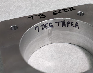
Overall, Bryan reported that it fit perfectly. The only issue was that the throat was a little offset on the TB side - which creates this little smile that you can see here:
During final assembly, he is going to hand work a little more chamfer into the adapter plate in that area to get rid of the "smile" and prevent any airflow disruption.
Another part of his project to adapt this engine to his FWF package is to create an adapter that will drive off of the transmission input side of the engine and into the PSRU. This pic gives and idea of what he needs to do.
I believe that this disk is part of his flywheel or torque converter from his engine.
I think Bryan is going to try to adapt this disk. If that doesn't go
well, I offered to help him machine a new plate from scratch. This might be a topic in a future update.
I have even started a CAD drawing of a ruff idea/concept for an adapter for his project:
Here is an example of this adapter mounted in someone else's FWF application. It is just to give an idea of what Bryan is also trying to accomplish with his setup?
Bryan is planning to use AutoPSRU's gear box for his FWF package. In August, after AirVenture, he loaded up his trailer, packed his RV and headed to Texas to meet with Stuart and Larry. For almost a week they worked on details of what it will take for Bryan to make his engine work with the AutoPSRU's 300Z gearbox.Here they are hard at work and "pounding out" the details:
The last report I got from Bryan was in Sep when he sent me these pics of his continuing work on his engine. It looks like he is refining the motor mount (to include mounting pads for the PSRU):
And, it looks like this is an oil tank that he will be adding to the system:
In our most recent conversation, Bryan was talking about removing his center section wing to make some modifications that will better support his new FWF systems. Remember, he originally built the center section with the idea in mind that he would be using the diesel engine package. For example, he was planning to use one of the wing root radiators specifically for oil cooling of the diesel engine. Now, that will not longer be the case. I will update more about his future plans as they unfold.
That's all I have for this "catch-up" update. Thanks for checking in again!
My next update is going to cover the remaining Prowler related items from 2024. I will try to have it out soon!
Monday, December 16, 2024
Subscribe to:
Post Comments (Atom)





No comments:
Post a Comment