Sunday, April 29, 2012

Lots of "Irons In The Fire"

Hello Again Everyone,Well, unfortunately this update is a little later than previously promised.  My apologies, but thanks for taking the time to stop-by and check out the latest "goin's on, that's goin' on" here at the new Prowler Aviation.

As the title of this post implies, I've got a lot of projects that are started, but most are lacking any level of completion yet.  The list of current projects (and items covered in this update) are:

1.   Finish assembling the entire main wing spar.
2.   Finish building the wing jig (that has been hanging fire for 5 years!).
3.   Finish building the "Prowler Rib Smasher."   The two problems holding up this project are:
3a.  Rebuilding the 100 hydraulic ram
3b.  Finding a "high speed" pump solution to work with the "high pressure" pump.
4.   Building an organized tooling cart for all the mill and lathe tooling.
5.   CNC project for a friend.
6.   Fixing the "Why won't it go, Daddy" on the Razor MX500 motorbike rear wheel.

One completed project for this update:

7.   I now have a DRO (Digital Read Out) on the Bridgeport mill (again).

Before I get started on the update, I really want to thank my father for all of his help and support over the years.  He as spent many hours helping me brainstorm, troubleshoot, build and/or fix a lot of the Prowler tools and machines that I will be using in production (hopefully) some day.  Also, while serving my apprenticeship (growing up fixing, building and working on all manner of things around the house and shop) I learned so much about how to accomplish a lot of these projects.  Were it not for this experience, I would never have gained the knowledge, insight or confidence to tackle a project of this magnitude.  So, thanks Dad.  I appreciate your help.

1. Finish assembling the entire main wing spar - I've finally cleared off enough space on one set of tables (from all the parts of all the other projects that are hanging fire) to begin doing the temporary assembly of the wing spars.  These parts are long and take up a lot of table space in one direction.  Here's a shot of the center section laid out with the RH outboard section.

Before I can really go any farther, I need to fabricate four (4) of the wing attachment plates that transfer the forces from the outboard sections to the center section.  I started this wing attach plate part of the project several years ago too.  I made up a fixture plate for a machinist buddy that had just gotten his first CNC knee mill.  Here's a pic of an old left-over inventory piece from George laying on the fixture:
We never got the chance to make these parts, and that's probably a good thing.  Since then, I've gotten my own CNC mill and I've actually completed the CAD drawings.  The CAD drawing and the hole pattern has changed since I first made the initial fixture (and is now different from what George made).  That means now I have to essentially start over with a new fixture and a new program to cut these plates on my mill.  In order to learn how to use my new mill, I decided to take on a side project for a friend.  More about this in Item 5. below.

These wing attach plates are the most important part of bolting the outboard wing spars onto the center section.  They are also integral in holding the MLG torque tube spherical bearings in place and help to align and hold the MLG torque boxes in place.  You can see how they are used in this pic from Ray's numerous photos:
So, getting the program developed and the fixture plate made to machine out these parts is getting pretty high on the priority list.  With what I've learned about using the Fagor8040M Controller on my mill in the past month, I should be able to get these made pretty soon.  Just a few more dragons to slay before this makes the top of the "to do list."

When I do have these plates finished, I will continue the process of figuring out how I will get the proper alignment and hold everything in place while I ream all the holes to the proper sizes for the temporary assembly.  Once the temporary assembly of the entire wing spar is complete, then I will be working on getting the wing jig completed (which is covered in the next Item below).  When I've completed building the wing jig, then the wing spar must be completely disassembled into parts and every part will have to be acid etched and then chromated (Alodined) before final assembly.  Then the entire assembly will go back into the jig.

2. Finish building the wing jig (that has been hanging fire for 5 years!) -  So, as you can see from the picture below, my dad helped me build the first phase of the wing jig way back in Mar 2007!
I am most frustrated that I've been walking around this wing jig in the shop for over 5 years!  (Look at how much room I had in my new shop back then!)  But, the logical progress of this project (and all of it's associated pieces) can only go together so fast.  Unfortunately, in the 5 years that the jig has been (mostly) installed, the it has become a long tray to hold all of my scrap steel, aluminum and other metal parts.
So, the first step of getting the wing spar installed into the jig is going to be to clean the jig back out and find a place to put all the metal that is "stored" there now.  That project is related to Item 4 below (tool cart).

What needs to be done on the jig, once it is cleaned out and ready for the spar, is to complete the location of the 4 center posts.  The two posts that you see in the picture are for mounting the ends of the outboard spars (actually attaching the tip ribs).  The location of these two posts is very well defined (by wing span).  The 4 center posts have a little variability.  Two of these 4 inner posts attach to the underside of the main spar (fwd side) just inboard of the MLG torque boxes and on the under side (fwd side) of the wing spar attach plates (see how all this stuff is related). 

The other two posts attach to the underside of the spar (fwd side) inside of the MLG wells and attached directly to a spacer plate that is placed between the spar cap strips on the fwd side of the spar.  The inner posts must be made removable so that you can remove one side at a time when the time comes to install/cycle the MLG.

Needless to say, all these posts have to be accurately placed, and be precisely the correct height so that the spar is completely flat and level when it is finally installed.  Fortunately, George had a pretty detailed and complete drawings to help build the jig and I have compiled a good set of reference pix from George and the previous builders..

3. Finish building the "Prowler Rib Smasher" -  The day after I get the spar finally assembled and installed in the jig, my focus will shift to "decorating" the spar.  By "decorating" I mean installing all of the "stuff" that gets attached to the spar.  The most numerous of these parts are all the wing ribs.  Obviously, before installing the ribs, I have to fabricate them and that is where the PRS (Prowler Rib Smasher) comes into play. 

I've addressed this topic many times in previous posts, but now I have the mechanical side of this forming press completed (with the help of my father).  My dad is a retired Ironworker and spends the winters "snowbirding" in Phoenix.  When spring comes, my folks drive out for a family visit before heading back to Wisconsin.  Having spent a winter without any welding, cutting torches, grinding etc., dad enjoys (I hope) having a project to work on with me in the shop.  This year it was the PRS, which is a 100 ton press that is (now) fitted with special box that will contain dies, blanks, and rubber while "squishing" the ribs into shape.

The first step was to evaluate all of the existing parts that could be used and then determine what steel needed to be obtained to form the lower "box" and the upper "lid." We also had to figure out how each of these was going to be attached to the frame of the press.  Here is a pic of the fabrication of the remodeled lower platen with "Pops" in the background:
Next, we discovered that the lower platen had been bent and had a pretty bad "hump" in the middle.  This had to be removed or the dies used to form the parts would get bent and the ribs would come out bent.  So, we fabricated a set of fixtures to hold the assembly in the mill and then installed it onto the mill bed.  Here's the fixturing:
And, the whole thing installed on the mill:
And, here is a shot while machining the platen back to flat:
The only area that has to be flat is the bottom of the "box" and you can see where there is no material removed from the lower right corner of the box.  There turned out to be a similar area in the upper left corner.  After getting the box bottom machined flat, the sides were added (short sides are 3/4" steel flat bar and the long sides are 1/2" flat bar with 3 gussets):
 The lid was fabricated from a piece of 5/8" plate steel that was recycled from a previous part of the press.  This was welded to 3 pieces of 6" I-beams laid on their sides.  Then all of this was welded to the upper frame of the press.  Here is a pic of all of the mechanical mods completed on the press:
Next, we assembled the hydraulics.  We converted a HFT air-over-hydraulics 10Kpsi pump to operate the 100 ram (converted bottle jack).  Since the volume of oil required to run the ram is more than the reservoir on the air-over pump we had to add more reservoir capacity.  The only thing handy in the shop was a spent fire extinguisher bottle.  So, here is what we came up with (don't laugh!  Atcually, this is really just a test setup to see if all this will/would work):
Once everything was hooked up, we tested the hydraulics.  Two problems became readily apparent.  First, the hydraulic pressure would bleed off (the system wasn't tight and the pressure would drop off over time).  Second, we found that the volume of oil flow through the air-over unit was really low (the ram moved very, very slowly).  These issues are discussed in the next items.

3a. Rebuilding the 100 Ram
After testing and finding that the pressure would not hold, we investigated the cause.  We determined that the ram's piston seal had to be leaking.  This started a 3-day project of re-boring and honing the ram cylinder and re-sealing the piston and ram cylinder.

The first step in the process was to make a spanner wrench to remove the ram packing retaining nut:
Then I had to machine (with the Bridgeport mill) a slug wrench that could be used to remove the big retaining nut on the top of the bottle jack.  (Notice the previous use of a chisel and hammer to remove this nut.)  This is the big nut that holds the whole bottle jack assembly together.  Here is the completed wrench, on the nut that has been removed from the top of the ram:
Here is a picture of the upper reservoir seal ring, the ram seal retaining ring, the ram packing seal, and the big retaining nut removed from the bottle jack:
Here is a pic of the 100 ton ram (converted bottle jack) with the upper retaining nut (etc.) removed.  You can see the outer jacket, the main cylinder, the top of the ram.  The area between the outer jacket and cylinder is the bottle jack reservoir (no longer used in this application).  The area between the cylinder and the ram is the difference in diameter of the ram and the diameter of the piston (can't see the piston here,as it is still down in the bottom of the cylinder)
Here is the bottle jack with the reservoir jacket removed:
 And here is a pic of the base with everything removed except the lower cylinder seal ring:
 Here is ram and piston removed from the cylinder (it's sitting upside-down on the bench - so the bottom of the piston is on top):
We found a fair amount of hydraulic fluid on top of the piston when we removed it from the cylinder. The only way for hydraulic oil to get there is for it to leak by the piston seal. This could be caused by a bad seal, a bad surface on the inside cylinder wall - or both. So, I decided to replace the seal and re-bore and hone the cylinder wall.  To tackle the re-bore of the cylinder, the base and the cylinder were clamped onto the mill.  I then set up the tooling to re-bore the cylinder inside diameter.  Here's a pic of the setup - I am using a dial indicator to get the cylinder wall as parallel as possible to the quill/spindle on the mill (in the X direction - I had to repeat this in the Y direction too):
Here's the first boring operation to clean up the inside wall of the cylinder - you can see the new, clean surface being made at the top (this is only about a 0.002" pass, but it looks like much more):
Once the cylinder was re-bored I put it into the drill press and set it up for honing.  Here's the setup:
This is the cylinder laying on the bench with a light in the background - nice, smooth and shiny:
On to the piston seal.  It took a bit of "gumshoe" detective work to find a replacement seal.  After a week of Internet searching, emailing and calling, I finally found the right place to make me a new leather seal for this ram.  The place turned out to be AFC Hydraulics in Vernon, CA.  Vernon is just south of downtown LA and I was able to go there while sitting on call during the day job (to pick up my new seal).  If you need any kind of hydraulic parts, seals, power units, etc.  give Oralia a call.  She did a great job helping me out and the "guys" did a very nice job making my new seal.  Check it out:
The old piston seal (lower left), the new seal (lower center), and the 1st new seal that I ordered incorrectly (lower right).  On the upper left is the retaining washer that holds the seal in place on the bottom of the piston.  On the upper right is the new lower cylinder seal ring that I also purchased from AFC Hydraulics.

Dad and I were somewhat surprised to find that these seals are still made of leather.  Turns out that despite more than 100 years of technological advances, leather is still the best material around for making seals in demanding applications.  There just isn't a better material that will form to irregularities on the sealing surfaces, remain pliable at extremely high and low temperatures, withstand abrasives, etc. etc.  Pretty amazing.

I just picked the new seals up Fri pm and won't be back in the shop until late on Sun.  I should have the 100 ton ram put back together on Monday.  It will be very nice to have this project off my plate (and off my work bench)!

3b. Finding a "high speed" hydraulic pump solution - When we tested the PRS, we discovered that the cycle speed of the ram is very slow (I expected it to be slower than when I was using it in the press brake - but not THAT slow).  So, now I have to find a way to quickly close the press (raise the 100 ton ram) until it begins to compress the rubber by some amount.  Then (I think) I'll have an isolation valve to isolate this "low pressure, high speed pump" from the system.  Once isolated, the high pressure, low speed air-over unit would compress the box fully to form the ribs. 

Reversing the process would be relieving the system pressure to the point that the valve was closed on the way up, then opening the valve and relieving the pressure the rest of the way into the high speed pump.  This process will have to be monitored to ensure that one or the other of the pump reservoirs doesn't overfill with hydraulic fluid. 

Another option is to install a larger bore manual pump (like the one removed from the bottle jack) to help move a lot of fluid fast, then switch to the air-over unit.  I'm not sure which way to go yet.  But, I've got a little time to figure it out before I really have to start squishing wing ribs. More to follow on this project.

4. Building an organized tooling cart -   As I get involved in more machining projects for the airplane, the amount of tooling that I've got laying around is getting a little unmanageable.  I've got some stashed here, some there, etc.  Well, a few months ago a buddy gave me two large drawer units that work excellent for storing all of the tooling, measuring, and setup equipment that is used with the mills and lathes.  Also, I have to find a place to store all of the metal bits and pieces that I have to clean out of the wing jig.

One day I had a revelation and decided that if I can find a nice, organized place to keep all of my machine tooling, then I can used the mish-mash of current shelves as space to store all the metal.  The only problem was building (and finding a place to put) the machine tooling cart.  I think I've found a little real estate in the shop for the tooling cart.  So work began (feverishly) on building the cart.  I scoured my junk piles and found steel, steel shelves, casters, etc. that would go together without too much effort.  Then I hauled out the drawer units and started to clean, scrape, bang, bend, sand and paint the drawer units back into decent shape (they'd been a little abused in the past).  Here is the current state of the project.  Here is one drawer shell setting on part of the newly fab'ed cart:
There will be two of these drawer sets, one on top of the other and then a top.  The the bottom shelf will be for all the heavy things like vices, rotary tables, etc.  Here are the drawers that have to be cleaned up, straightened and unbent (some of them):
Once it is all back together, the process of organizing and moving all the tooling into the drawers can begin.  That'll be in a follow-up post.

5.   CNC Side project -  I have a friend that needed some help getting a CNC project underway.  He asked me if I would give him a hand getting some programming and parts done.  I was kinda looking for a project to help me learn to use my Ganesh CNC mill.  So, we agreed on some terms and I set out to get it done.
So far, I've gotten the majority of the fixture plate (and sub-base) fabricated.  This fixture plate will hold an entire set of the parts that he sells online for a product that he makes. Here is a pic:
All that remains to be done is place (pretty precisely) the mitey bites that hold the pieces of stock in place.  Then I can begin to process the G-code to do the necessary operations on the pieces of stock.

In order to get some product out the door, I used my CNC mill and wrote the needed code to finish a set of his parts. He had gotten behind on several orders and really needed to get some product out the door so I completed the 1st  15 sets of parts a few weeks ago.  Here are some examples of the parts to be made:
I'll have a few more parts runs to do to fulfill our agreement.  But, now that the parts programs are written, they can be run anytime.  That's the beauty of CNC machining.

6. Fixing the "Why won't it go, Daddy"-  On a recent arrival home after the "day job" I was informed that the small electric motorbike that the girls have wasn't working.  After a fairly quick investigation it became apparent that the clutching mechanism that allows the rear wheel wheel to "free-wheel" when the electric motor is not on and working was worn beyond repair.
Here you can see one of the little dogs that the wheel can free-wheel over in one direction, but then "takes a bite" if turned in the other direction.  The dogs were all chipped and worn as well as the teeth in the other part.  The spring that holds the dogs was also mangled.   Best just to replace it all.
  A short Internet search yielded a replacement rear wheel assembly that is making its way to the shop via UPS Ground.  We should have it back together soon.  All in all, it was a fun little project to do with the girls.

Now, for the ONE project that I HAVE finished!
7.   Bridgeport Mill DRO - I recently got a good deal on a new DRO for the mill.  It's an Anilam Wizard 411 made by Acu-rite.  The instructions were easy to follow and it basically took one full day to install the readout and the scales onto the mill.  Here's a pic of the Y axis scale installed:
Here's the X axis and the Y axis scales installed on the mill:
And this is the control head installed:
When I finally disabled the old DRO that the Bridgeport came with, it was a tough call to make.  But it was an old, unreliable system.  While it took over a year to finally get it replaced, it was really a good thing - actually.  It forced me to use the mill in the old fashioned "hand cranker way."  That was valuable experience that has given me much more insight into the world of machining.  With that said, it's nice to have the capability of the DRO back on the mill now.

That's all for this update.  Hopefully, I will get another update done in a few weeks showing some closure on a lot of these projects.  Until then, have a great spring season and thanks for stopping by to see the progress (or sometimes the lack of progress) here at the new Prowler Aviation.

Monday, March 12, 2012

Prowler Kit #13 For Sale

This is a special blog post dedicated to Roy's Prowler Kit #13.  Roy is forced to sell his airplane, and I thought posting the information here might help him accomplish this.
Here are some of Roy's Comments:

 Ron Chamblin from Jacksonville, Fla.  purchased kit #13 in the mid 1980’s after seeing the prototype at Oshkosh.  He was advised (full-time) by an A&P to help him build it.   After 5 years of full time work, he was getting tired of working on it.  The orignal Prowler Aviation had closed its doors and Jaguar #1 (the kit prototype) came up for sale.  Ron then also bought the 1st company aircraft (the RW&B airplane).

Work began to repair the RW&B but was halted at some point, and no one seems to know why.  Both aircraft sat idle in Ron's shop/barn for many years untouched. I had contacted him a few times about buying the kit but he would not sell.

A few years later Rick Pellicciotti (from Memphis) was able to strike a deal with Ron to purchase all the Prowler/Jaguar stuff that he had.   Rick really wanted Jaguar 1 and will be restoring it to flying condition.  I eventually purchased kit 13 from Rick.

This is a unique and interesting airplane. It is for the serious builder as there will be some fabrication required. What you see is what you get. There are numerous parts that are missing and/or were never supplied.  Except for the fairings and inner gear doors, the basic airframe is there and mostly complete.   Just add engine, instruments and go fly!

I have not touched the airplane except to put it together so I could look at it and drool.  Here is what is included with Prowler Kit #13:
  • Ailerons are completed.
  • Flaps are completed (see note below).
  • Vertical Tail is completed.
  • Rudder is completed.
  • Horizontal Stabilizer is completed.
  • Elevators are completed.
  • Fuselage is mostly completed from the firewall aft. Landing gear, including the retractable tail wheel is installed. Most of the hard line hydraulic plumbing is complete, but no hydraulic cylinders or hydraulic hoses. The hydraulic pump is installed. There is also a lot of wiring already in place.
  • The outer wings are mostly completed. The top skin riveting is not complete since there is some fuel tank work that still needs to be completed.
  • The Radiator Assemblies are mostly complete.
  • Canopy and Windshield are included.
  • Canopy frame included.
  • Elevator Push Pull Tube included.
  • A few boxes of assorted parts.
NOTE: There are two damaged spots that were on the airplane when I purchased it. 1st spot - One of the flaps has a dent in the trailing edge. I was going to re-skin the flap, but several people tell me they would cut it out, patch it, and then fill it so it doesn’t show. Skinning the flap is my choice and not that big of a deal.  2nd spot - There is damage on the lower fuselage at the tail wheel retract area. It looks to me like the tail wheel (at some time) unlocked and retracted into the wheel well.  Maybe when it was being moved or something.  It has caused a crack about 1 ½" long on both sides of the wheel well cutout.  My plan was to cut this area out and make an access panel. It’s a simple fix and would provide better access to the tail wheel retraction mechanism for inspection and maintenance.

Here are several pictures of the airplane to view.  I will be glad to take any additional pictures you would like and send them to you.  My name is Roy.  Please send me an email at: 
(insert my first name here)farris1(_at_)comcast(_dot_)net.


If you are unable to contact Roy at the email address above, you can contact me at the Prowler Feedback Contact Page (HERE) and I will forward your message/information to Roy.

If you are interested (or know someone interested) in a Prowler project that is off to (what appears to be) a great start - contact Roy.  Thanks.

Friday, March 9, 2012

Press Brake Success! Spar Parts Complete.

Hello Again,

Thanks for stopping by to check on the progress here.

Well, after many tweaks, lots of calibration and then more testing - I've finally found success bending 2024-T3 with the press brake that we built last March.  Now, with the ability to cut out parts with the MotionMaster router and then bend them with the press brake, I finally have the processes in place to make many of the airplane's parts.  This includes any part that is cut from flat stock and then has any kind of straight flanges or bends required to complete the part.

This capability allows me to make all of the aluminum main spar parts (both center and outboard sections), and most of the steel main spar parts.  Part of this update includes the set-up of my Ganesh CNC 3 Axis Mill that will allow me to make the 4130 steel parts that I need to build the main spar.  Shortly, I will have the all of the spar parts I need to assemble the entire main spar and install it in the wing jig.

When I do get the main spar installed in the jig, my focus will shift to buying and/or building the machines to give me production capability for the airplane parts that I need to made using the rubber-hydroforming process that I've mentioned in previous posts.  Of course, progress on the airplane will (necessarily) slow down a lot while I work on these rubber pressing projects.  But, once complete, I will have the ability to press out my wing ribs, install them onto the wing spar, and continue to build the wing structure.

The capability to press these parts will also mark the time when I have production capability for most of the airplane - the only notable exception being the majority of the landing gear parts.  Historically, the landing gear gets installed after the wing is completed in the jig.  The center section gets removed from the jig, flipped upside-down on the cockpit floor and then the landing gear is installed onto the torque box torque tubes.  Since I have a while yet before the wing is complete, there is time to to contemplate the production of landing gear parts.

OK, that's the very short term, short term, and medium-term future plan/goals here.  But, now, let me catch you up on what I've been up to in the past 3-4 weeks.  In this update:

Press Brake Back-Gauge Completion
Press Brake Calibration
Outboard Wing Spar Channels
Center & Outboard Skin Flanges and Bridge Shims
Wing Rib Attach Angles
Ganesh GMV-2 CNC 3 Axis Knee Mill Set-up
Builder Updates
   Ray,Chuck & Bud
   Bryan
   Roy - Kit 13 For Sale
Press Brake Back-Gauge Completion -  The flanges on most parts are uniform in width, so I wanted to have a convenient way to set the width of the flange for pressing.  I came up with this system that allows me to quickly set the flange width.  This pic shows the set-up out of the press:
 With the distances involved, I had to add a "spacer" to be able to get the scales placed in an acceptable area.  So, I riveted an aluminum angle to the back side of the back-gauge.  Once installed in the press, and after a few test bends, I was able to accurately calibrate the counter-sunk scales.
Here's a overview of the whole assembly out of the press:

Press Brake Calibration -  In a previous post, I outlined the beginning of the press brake calibration and bending of  test strips.  During that time  I found that I could not just bend clips at each end of the lower die beam, but to get more accurate results I also had to have a piece in the center of the die.  So, I started bending sets of 3 pieces and trying various plunge depths.  As I did this, I noticed a few things that were affecting the consistency of the bend angles.  First, I determined that using the hydraulic system (that I outlined in a previous post) was causing variability because it was essentially "overkill."  The hydraulic rams were pushing on the stop blocks too much and flexing the entire press brake - producing inconsistencies.
The second thing I noticed was that I was getting some strange warping of the parts that I was bending.  I wasn't sure if that was because of the press brake, or the material.  I suspected that is was the material causing this warping, because it was SO uniform.  I figured that the press brake couldn't be doing this so perfectly uniformly.  Here's a CAD drawing that simulates the warping that I was seeing:
In an effort to figure this out, I found a website called www.homebuiltairplanes.com that has a sheet metal forum for questions.  I posted on this site and eventually got some great feedback that did help explain what what happening.  Turns out that this warping is called "cambering" and IT IS a function of the material.  As the material gets stretched and compressed along the bend line, it causes this warping to happen.  You can check out this link to the thread for more info.

Armed with this knowledge, I found a way to deal with this deformation and was finally ready to try some long pieces in the brake.  I decided to start on some 2" ID channels, since there are many of these in the airplane and if I messed them up too bad, I wouldn't be wasting too much money.  By the time I completed the third channel the bends were coming out pretty nice.  Here's a pic of the first two channels lying on the mat and looking down the edge of the 3rd channel :
By the time I'd gotten the third channel bent up satisfactorily, I got brave enough to try one of the outboard wing spar channels.  That's next.

Outboard Wing Spar Channels -    Here's the first spar channel in the press:
Here you can see the finished product - fresh from the press brake and with the long spar cap strips installed onto the channels. They came out great.

This was a big turning point for me in the quest to re-establish some limited production for Prowler Aviation.  It gave me a lot of satisfaction and motivation.   A lot of what I've been working on for many years now is represented in these two parts.  I've actually been working on a satisfactory way to bend these long pieces for over 3 years - starting with the unsuccessful attempts to repair and modify the 8 foot sheet metal leaf brake.

So, completion of these outboard wing spar channels was REALLY noteworthy because:
1. They were cut from G-code that came from the CAD drawings that I've been working on for over 2 years;
2. They were cut in the MotionMonster CNC router that I'd spent much of last year repairing, modifying and installing in the shop. And;
3. The were bent in the one-of-a-kind, purpose built press brake that my dad and I designed and built while he was visiting last March.

This was a pretty sweet success!

Center & Outboard Skin Flanges, and Bridge Shims - Energized by the success with the spar channels, I moved on to the wing spar skin flanges.  Here are the forward skin flanges for the center section.
Here are the aft skin flanges for the center section of the main wing spar:
The next parts on the "To Do" list were the spacers that fit between the upper and lower spar cap strips under the wing rib flanges (both on the center section and the outboard sections).  Here is a shot of one set of these spacers in the mill getting machined down to size:
Here's the entire set of the spacers:

Wing Rib Attach Angles -  The last of the aluminum parts that I needed to fabricate were the angle clips used to mount the wing ribs to the main spar.  Since I don't have a sheet metal shear (yet), I used the MotionMonster to cut some 1-3/4" strips from a 4' piece of 0.050" aluminum (on the right in the picture below).  The parts in the middle (below) are specially shaped rib attach angles that go on the inboard rib of the outboard wing section.  The piece on the left is for the wing pylon attach points (that is actually left-over stock from George, so I didn't need to fabricate that piece).
Once I got the stock cut into strips, it was time to cut the strips to the correct lengths:
Then, bending in the press brake was next:
Here's the completed parts after bending in the press brake.
The bends are coming out very nice - correct angle (90 deg) and uniform over the length of the angle:

 Ganesh GMV-2 CNC 3 Axis Knee Mill Set-up -  So, with all of the aluminum parts of the spar complete, the only parts left to make for the spar are steel parts.  These parts are made from 4130 chromoly steel.  Because the forces involved in cutting the steel go up, they require a bit more fixturing to hold them while cutting.  The vacuum table on the router isn't capable of holding the material for these parts - so it is time to get the CNC mill running.  The first task was to find a place to put it in the shop.  The shop is starting to get full.  But, I decided to take a day and move the mill into a position near the Bridgeport manual mill - since I have the 3phase power there, a lot of the tooling there, and it's closer to the workbench (I can't tell you how many 60 foot round trips I made to the workbench while setting up the MotionMonster!)  So here's a pic taken just after rolling the CNC mill into position with 3/4" pipe.
Next was getting power set up to the machine.  Here's a switch box that I wired up to turn on power to part of the machine:
Here is a picture of the machine in it's new home spot in the shop:
This is a close up view of the controller on the CNC mill.  It is (coincidentally) made by the same company that made the controller for the MotionMonster - only a few generations newer.  The router has the Fagor 8025M controller and the CNC mill has the Fagor 8040M controller.  This is a much more capable controller, but it is also going to take a bit longer to learn how to use - it seems.  Here's an older file photo:
Once I got the machine powered up again, I went to work getting it hooked up to a laptop computer.  After a little messing around, I got the machine to sync with the laptop software and got the following screen shots:

Here's what the software looks like on the laptop.  This is the WinDNC software provided by Fagor.  It actually does a pretty good job working with the mill controller.  It even has a remote keyboard function that allows me to control the machine from a the workbench across the shop.  That's cool!
Here's the first job that I'm going to tackle with the mill:
This is the wing spar attachment plates and the fixture plate that I made up to hold these parts during machining.  This is a left over piece of inventory that I got from George.  Turns out, I modified the hole pattern on this part just a little bit during the CAD process.  I did this because, as it currently exists on this part, the hole pattern was not quite symmetric or uniform.  I made it symmetric and uniform, so that now these plates can be used universally on any of the 4 spots on the airplane - AND the holes line up perfectly with all of the wing spar cap strips, skin flanges, etc.

Builder Updates -
Ray, Chuck & Bud - It's been a while, so I checked in with Ray recently.  Ray is recovering from some neck surgery, but should be getting more done with his engine work soon.  In the meantime, he's been working on paperwork, checklist, and other "lite duty" tasks associated with building the airplane.  He reports that Chuck is continuing to have fun flying his Prowler.  Apparently, his airplane (even without the supercharger) will do high speed passes at the airport that might have been just a tad over the speed limit.  Of course, this is all rumor and third party info - so take it FWIW.    Also, rumor has it that Bud is close to running his engine again.  I hope to have better updates from them all next time. 

Bryan - Meanwhile, Bryan sent a few pictures with some questions/discussion about tailwheel doors.  He's finalizing the design of his TW doors and operating gear.  I'll report more on this in a future post - but here's a couple of pix of what he is thinking about:


Roy's Kit #13 is still FOR SALE - Roy is still looking for a good home for his Kit #13.  Here are a few pix:


  If you are interested, please contact me via the website feedback link and I will pass along contact info.  If you know anyone interested in a kit, please provide them with this info.  Thanks.


Well, that does it for this update.  I hope this was informative and maybe even entertaining.  Thanks for stopping by.  I'll post an update again in early April.

Friday, February 10, 2012

A Prowler For Sale + Spoilboards and Skin Flanges

Hello Everyone,
Thanks for stopping by.  The past two weeks yeilded 5-6 more days in the shop.  It woud have been more, but I had to do my 2011 taxes, honey-do's, and some kid stuff.  Overall, it's been a fairly productive couple of months in the Prowler shop.  The time required on the day-job is going to step up for the next several weeks, but then I'll have "Pop in the Shop" the last 10 days of March - so we'll get something done then, for sure.  In this update:

1. George Stopped By The Shop.
2. A Prowler For Sale
3. MotionMonster Spoilboard Refacing.
4. Main Spar Center Section.
5. Center Section Skin Flanges.
6. Chuck's Having A Blast.

 I didn't work much with the press brake in this past two weeks.  I'm still working things out (in my mind) as to how to "calibrate" this machine.  I'm now certain that it will bend this aluminum, and it will make nice bends.  The trick is going to be getting it to bend at the desired angles, consistently.  The other trick is going to be trying to get "calibration data" without cutting up and wasting a bunch of 2024-T3 that cost $250 a sheet.  So, it's the next item on the agenda, and I plan to work on this exclusively the next days I get in the shop.  Mostly, my progress on the airplane will soon grind to a halt because every part needed to complete the spars will be needing to be bent in the press brake.  So, like many things in life, the criticality of needing this process to work will soon take over and "drive the bus" for a while.
The upside to this is that when I finally conquer the beast, I will have production processes in place to produce about 50-60% of the airfame (minus the landing gear and some torque box parts).  Approx. 10% would be all the chromoly steel welded parts in various places on the airplane.  The remaining 20-30% involves the process of rubber pad pressing (low budget hydroforming) to make all of the formed parts (wing ribs, bulkhead formers, etc.)  I've discussed a lot of this technique and the future plans for it in previous posts.  With that being said, on with the update.

1. George Stopped By The Shop -  George stopped by the shop last week to drop off the flyers in the segment below.  He has recently gotten hooked up to high speed internet and has found our blog site.  He came by to ask if I would post the for sale flyers he made up for his airplane on the blog.  At 84 he is doing great and even thinking about undertaking a Prowler project - for something to do.  If anything develops on this front, I'll report on it in a future post.

2. Prowler For Sale -  George has had his 3rd Prowler for sale for a while now.  These are the flyers he asked me to post here on the blog.  The airplane is currently hangared at the Red Bluff, CA airport (KRBL).

If you are interested or have any questions, George's contact info is on page 1.

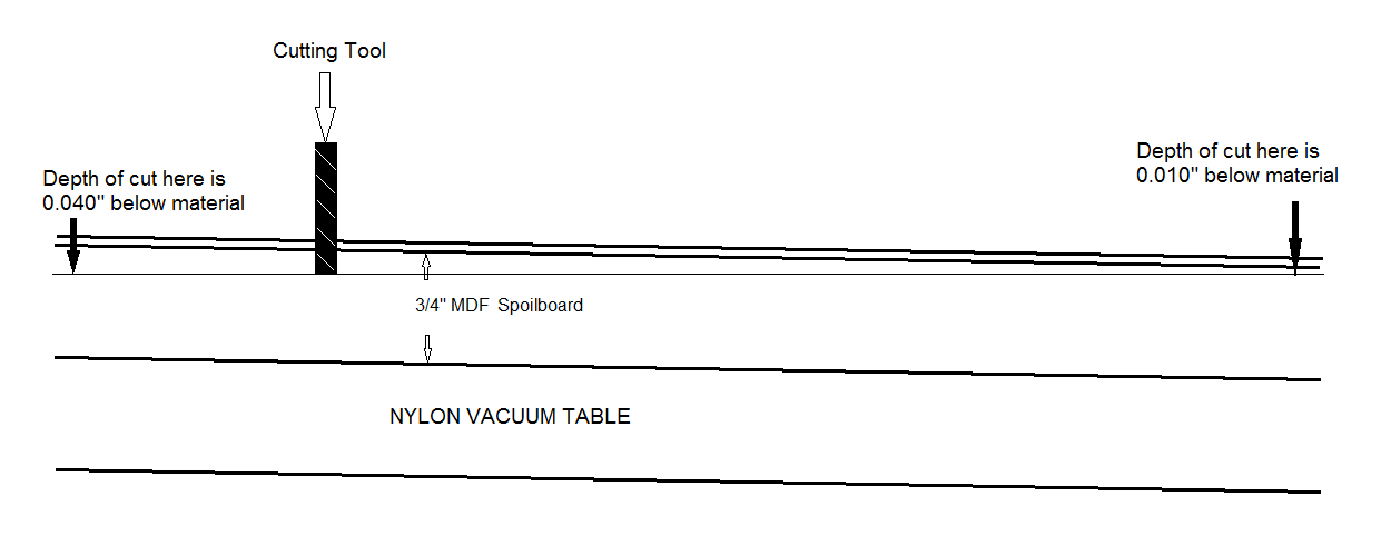
3. MotionMonster Spoilboard Re-facing -  I finally got around to cleaning up the spoilboard on the MotionMonster.  This has to be done anytime you mount a new spoilboard on a CNC router.  There are two main reasons for needing to do this: 1) the main X and Y axes are not perfectly parallel to the top of the vacuum table that the spoilboard is installed on; 2) The spoil board is not a uniform thickness.  In the case of the MotionMaster, the main stationary gantry that is the X axis (and has the spindle carriage mounted to it) is pretty large and heavy.  The best that I can tell, the gantry is about 0.030" out of parallel with the vacuum table/spoilboard.  That's not bad, considering the thing weighs in at about 2 tons.  There are several ways to try to physically make the gantry perfectly parallel to the table.  But, for this small amount the easiest way is to just shave off the difference.  Here's a picture to show what's involved (angles are exaggerated and amplified for clarity):
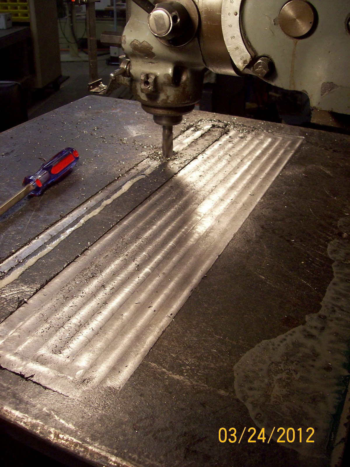
As you can see in the pic above, if the surface of the spoilboard is not perpendicular and planar to the spindle/tooling, then in order to make sure that the cutter clears the bottom of the material on one side, you have to cut even deeper on the "high" side.  So, the solution is to cut the entire sheet down to be even all over the face of the spoilboard.  Then, when you lay a sheet of material down to cut, the cutter will cut below the bottom of the material by the same amout all over the spoilboard.  Here's a pic of the facing operation.  It looks like a lot of material being removed, but in reality it is less than 1/16th of an inch.  I used a 1-1/2" mortise end mill with a 1/2" step-over to cut the face of my spoilboard down.  It was a little dusty, but it worked well, overall.

4. Main Spar Center Section -  When edge milling the parts of the spar made from the thicker sheets of .100" and .160" (described in the last post), you find out that it doesn't take long before you can get a razor edge on the corners of all the milled pieces.  This is particularly bad in two respects: 1) you can get some really nasty cuts; and 2) it is a property of most metals to form stress cracks (from fatigue failure) at the thinnest point in the material.  These stress cracks, once started, will propagate thru the material if left unchecked.  So, to prevent this from happening, you simply file the edges with a single cut mill file so that the edge has a small radius.  Now, you take these fatigue stresses and spread them out over a bigger surface area and the cracks are less likely to start.
Well, doing this to exactly 18 edges on 19 pieces might be simple, but it is also tiedious.  So, over the past couple of weeks I would do one or two pieces a day, while the router machine was running and it helped to spread-out the "tediousness" (is that a word?).   Anyway, now all of the thick center spar pieces are done and waiting to be hit with the scotchbrite and then the alodine.  Here is the "stack."


 5. Center Section Skin Flanges -   With the spoilboard faced off and armed with a couple of new 1/8" router bits, I decided to give another try at cutting parts.  I was a little "gun shy" of going at this again, with the number of broken bits in my router parts box far outnumbering the ones that are still in tact.  But, I "manned-up" and turned on the machine.  I started using a new style of bit for the first time.  This time a used a 2 flute, straight flute, 1/8" carbide cutter.  The straight flutes are very good for this profile type cutting application because it puts all the cutting forces directly parallel to the centerline of the material and does not try to lift the material off of the vacuum table/spoilboard (like a helical cutter does).  It works much better.  This time I also started with a lot higher spindle speed and a lot lower feedrate. I started with 12K rpm on the spindle and feedrate at 4ipm.  I could tell that I was making aluminum powder for chips so I slowly, step-by-step kept moving the feedrate up and by the time I was done I was cutting at 14K rpm and 10ipm.   I managed to cut out the 10 pieces of the center section spar skin flanges without breaking a bit.  So far, so good - I still have the same cutter in one piece!  Here's a couple of pics:

These are the lower skin flanges for the center section spar being cut. 

 It turns out that at 14K rmp, I should actually be able to feed that cutter at up to 18 ipm.  So, on my next attempt, I'll step the feedrate up a little more.  Overall, I'm very happy with the results.  The parts come out with a burr on the edges (as expected), but they are accurate.  I can match skin flange rivet holes to the holes in the spar caps - and they match, perfectly!  This CNC stuff really works.  It's encouraging.  I am imagining the possibilities to be able to do "matched hole drilling" for most of the parts of the airplane.  The time savings for future kits (builders) would be huge - as compared to previous methods.  Rest assured, I will be working this into the prodcution process whenever and where-ever possible.

 6. Chuck's Having a Blast - Just one quick builder update this time.  I have it from a reliable source that Chuck has been flying his Prowler quite a bit lately.  He is apparently "having a blast" flying his plane.  Rumor has it that the airplane has been operated fairly close to the speed limit, fairly close to the (minimum) altitude limit, and in VERY close proximity to his own house!  Huh - imagine that.  Congratulations Chuck.

That's about all the news that worth using up electrons to post about.  I expect with the work sked coming up and the folks visiting in late Mar, I'll probably try to post an update in early Mar and then again in early April.

As always, thanks for stopping by to check on the progress here at Prowler Aviation.